1
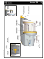
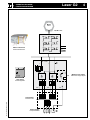
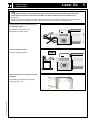
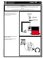
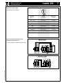
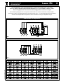
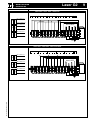
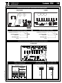
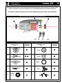
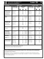
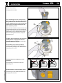
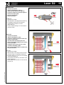
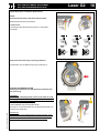
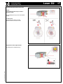
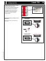
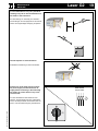
Ref. No. 28-8932-0817-01/0826 IRO AB Box 54 SE-523 22 Ulricehamn Sweden Tel: (Int+46) 321 297 00 Fax: (Int+46) 321 298 00 www.iroab.com [email protected] Laser G2 Operating Instructions xxxxxxx GB/CH English/China Laser G2 CONTENTS INHALT Technical specifications ............................................................................................. 2 Main parts .................................................................................................................... 3 Operating diagram ...................................................................................................... 4 Installation ................................................................................................................... 5 Mains connection ........................................................................................................ 6 Wiring diagram............................................................................................................. 9 Connections . ............................................................................................................... 10 Jumper.......................................................................................................................... 11 Yarn control ................................................................................................................. 12 S/Z Adjustment ............................................................................................................ 14 Threading ..................................................................................................................... 15 Balloon adjustment ..................................................................................................... 16 CAT adjustment ........................................................................................................... 17 Sensor adjustment ...................................................................................................... 18 Maintenance . ............................................................................................................... 19 Fault finding ................................................................................................................. 20 Declaration of conformity............................................................................................ 22 xxx ................................................................................................................................. 2 xx ................................................................................................................................... 3 x . ................................................................................................................................... 4 x . ................................................................................................................................... 5 x . ................................................................................................................................... 6 x...................................................................................................................................... 9 xx ................................................................................................................................... 10 x . ................................................................................................................................... 11 x . ................................................................................................................................... 12 x . ................................................................................................................................... 14 x...................................................................................................................................... 15 x...................................................................................................................................... 16 xx.................................................................................................................................... 17 xx ................................................................................................................................... 18 xx ................................................................................................................................... 19 xxx ................................................................................................................................. 21 xx.................................................................................................................................... 22 Ref. No. 28-8932-0817-01/0826 ORIGINAL LANGUAGE INSTRUCTION IRO AB RESERVE THE RIGHT TO CHANGE THE CONTENTS OF THE USER’S GUIDE AND TECHNICAL SPECIFICATIONS WITHOUT PRIOR NOTIFICATION. xx. Putat vel ullaore dunt in vel et la am venis del ute eum quiscilis exer ametummy numsandiam nonsenisit veliquat. Dui blaor ing eum zzrit wissi. Laser G2 TECHNICAL SPECIFICATIONS TECHNISCHE SPEZIFIKATION WARNING! CAUTION MUST BE TAKEN IN THE CLOSE VICINITY OF THE FEEDER AS IT CONTAINS MOVING PARTS THAT CAN CAUSE INJURIES AND, IN NORMAL OPERATION, STARTS WITHOUT PRIOR WARNING. THE POWER SUPPLY MUST BE SWITCHED OFF AT THE MAINS BEFORE ANY WORK IS CARRIED OUT ON THE FEEDER, THE TRANSFORMER OR ANY OTHER ELECTRICAL COMPONENTS. THE FEEDER AND THE TRANSFORMER CABINET MUST BE FULLY ASSEMBLED BEFORE THE POWER SUPPLY IS CONNECTED. THE FEEDER AND TRANSFORMER CONTAIN ELECTRICAL COMPONENTS THAT RETAIN AN ELECTRIC CURRENT UP TO THREE MINUTES AFTER DISCONNECTION ALL WORK ON ELECTRICAL COMPONENTS MUST BE CARRIED OUT BY A QUALIFIED ELECTRICIAN. THIS PRODUCT IS NOT INTENDED FOR USE IN POTENTIALLY EXPLOSIVE ATMOSPHERES OR IN ZONES CLASSIFIED ACCORDING TO THE EUROPEAN DIRECTIVE 94/9/EC. PLEASE CONTACT IRO AB IF PRODUCTS FOR USE IN A POTENTIALLY EXPLOSIVE ATMOSPHERE ARE REQUIRED. TO COMPLY WITH C. E. REGULATIONS ONLY REPLACEMENT PARTS APPROVED BY IRO AB MAY BE USED. The feeder is an industrial product and therefore not approved to use household environments / in residential areas. WARNUNG! IN DER UNMITTELBAREN UMGEBUNG DES VORSPULGERÄTES IST VORSICHT GEBOTEN, DA ES BEWEGLICHE TEILE ENTHÄLT, DIE VERLETZUNGEN VERURSACHEN KÖNNEN, UND IM NORMALBETRIEB OHNE VORHERIGE WARNUNG ANLÄUFT. VOR DER ARBEIT AM VORSPULGERÄT, AM TRANSFORMATOR ODER AN ANDEREN ELEKTROTEILEN MUSS DER STROM AM NETZANSCHLUSS AUSGESCHALTET WERDEN. VOR DEM ANSCHLIESSEN DER STROMVERSORGUNG MÜSSEN VORSPULGERÄT UND TRANSFORMATOR GANZ ZUSAMMENGEBAUT WERDEN. DIE SPEICHER UND TRANSFORMER SIND MIT ELEKTRONISCHEN KOMPONENTEN BESTÜCKT DIE NOCH BIS 3 MINUTEN LANG EINE GEWISSE ELEKTRISCHE SPANNUNG HABEN, NACHDEM DIE STROMVERSORGUNG ABGESCHALTET WURDE. ALLE ARBEITEN AN ELEKTROTEILEN SIND VON EINEM QUALIFIZIERTEN ELEKTRIKER AUSZUFÜHREN. Dieses Produkt darf nicht in einer brandgefährdeten Umgebung oder gemäss den Europäischen Vorschriften 94/9/EC eingestuften Zone verwendet werden. Bitte kontaktieren Sie IRO AB, wenn Sie ein Produkt für solche Umgebungen wünschen. GEMÄSS CE-REGELUNG DÜRFEN NUR VON IRO AB GENEHMIGTE ERSATZTEILE VERWENDET WERDEN. Das Vorspulgerät ist ein Industrieprodukt und deshalb für die Verwendung imPrivathaushalt nicht geeignet. Technical specifications • Technische Spezifikation Max 1400 m/min 76 dB (A) 4,9 kg Max 5 mm Min 5° C-Max 40° C 5,5 - 7 bar Max 85 % Max 2,2 mm Ref. No. 28-8932-0817-01/0826 Power Supply • Stromversorgung 200 - 575V 400VA 3,3 kg Max T 10A Fuse/ Zicherung S/Z Switch S/Z-Schalter Ref. No. 28-8932-0817-01/0826 Mount Befestigung Indicator Anzeigelampe Winding disc Wickelscheibe ON/OFF Switch EIN/AUS-Schalter Yarn break detector Fadenbruchwächter Spool body Spulenkörper Yarn store sensors Garnlagersensoren Tension ring quick-release Spannring schnell abhebbar Balloon control adjuster Ballonkontrolleinstellung Adjustment Einstellung CAT MAIN PARTS HAUPTTEILE Laser G2 Laser G2 OPERATING DIAGRAM FUNKTIONSDIAGRAMM Motor Motor 13,8 Ω +/- 5% TB2 S/z Motor control unit Motorsteuereinheit TB1 ON/OFF + + P3 – P10 P2 Fuse panel Sicherungstafel P1 Ref. No. 28-8932-0817-01/0826 Transformer Transformator Mains supply Hauptanschluss P1 P1 Machine stop signal Maschine-Stopp-Signal INSTALLATION INSTALLATION Laser G2 NOTE Condensation can form on the weft feeder when it is moved from the cold environment of the warehouse to the warmer environment of the loom room. Make sure that the feeder is dry before switching it on. ACHTUNG Kondenswasser kann sich bilden, wenn der Fadenspeicher aus der kalten Umgebung des Lagers in den wärmeren Webraum gebracht wird. Bitte darauf achten, dass das Gerät trocken ist, bevor es eingeschaltet wird. The unit should not be mounted directly on the weaving machine. Die Einheit darf nicht direkt an der Webmaschine montiert werden. Use a separate floor stand. Separates Gestell verwenden. Ensure that the mount screws are correctly tightened. Ref. No. 28-8932-0817-01/0826 Sicherstellen, daß Befestigungsschrauben richtig angezogen sind. MAINS CONNECTION NETZANSCHLUSS Laser G2 IMPORTANT! Turn off the main switch before any work is carried out on the electrical circuit. WICHTIG! Hauptschalter vor der Arbeit am Stromkreis ausschalten. The power supply to the feeder must not be disrupted when the weaving machine stops. Bei Anhalten der Webmaschine darf die Stromversorgung des Vorspulgeräts nicht unterbrochen werden. Mains supply Netanschluss Main switch Hauptschalter Emergency stop Notstop Schalter The phase sequence does not effect the direction of rotation. Phasenfolge hat keinen Einfluss auf die Drehrichtung des Gerätes. Ref. No. 28-8932-0817-01/0826 L1 L2 L3 Z S Laser G2 MAINS CONNECTION NETZANSCHLUSS Variations in main voltage. Zulässige Netzschwankungen. Nominal Nominal Voltage Spannung Frequence Frequenz 200 - 220 V 190 - 230 V 50/ 60 Hz 260 V 235 - 285 V 50/ 60 Hz 346 V 310 - 380 V 50/ 60 Hz 380 V 340 - 420 V 50/ 60 Hz 400/ 415 V 365 - 445 V 50/ 60 Hz 440/460 V 405 - 495 V 50/ 60 Hz 480/ 500 V 440 - 540 V 50/ 60 Hz 550/ 575/ 600 V 520 - 630 V 50/ 60 Hz Check the wiring diagram before any connections are carried out. With main switch Mit Hauptschalter Vor dem Anschliessen Verdrahtungsplan prüfen. Ref. No. 28-8932-0817-01/0826 Without main switch Ohne Hauptschalter Laser G2 MAINS CONNECTION NETZANSCHLUSS The wiring diagrams on the following page refer to control boxes equipped with a main switch (as in fig.1 below). The mains supply shall be connected to L1, L2, L3 and EARTH. When the control box is not equipped with a main switch the mains supply shall be connected as in fig.2. Das Verdrahtungsdiagramm auf den folgenden Seiten bezieht sich auf die Kontrollkasten mit Hauptschalter (wie in Figur 1 unten). Der Hauptanschluss soll verbunden werden mit L1, L2, L3 und Erde. Wenn der Kontrollkasten nicht mit einem Hauptschalter ausgerüstet ist, soll der Anschluss wie in Figur 2 abgebildet erfolgen. With main switch • Mit Hauptschalter Fig 1 Without main switch • Ohne Hauptschalter Ref. No. 28-8932-0817-01/0826 Fig 2 Laser G2 WIRING DIAGRAM SCHALTPLAN 200V/ 220V - 346V - 380V - 400V/ 415V 200V / 220V 346V 380V 400V / 45V L L2 L3 135 v green P1/1 SEC R PRIm Mains supply Netanschluss 10/9.5 v white P1/4 135 v green P1/2 SEC S PRIm 10/9.5 v white P1/5 135v green P1/3 l1 l2 T PRIm SEC l3 10/9.5 v white P1/6 1 3 5 2 4 6 PE 440V/ 460V - 480V/ 500V - 550V/ 575V/ 600V 440V / 460V 480V / 500V 550V / 575V / 600V L1 L2 L3 135 V Green P1/1 SEC R PRIM 10/9,5 V White P1/4 135 V Green P1/2 Mains supply Netanschluss SEC S PRIM 10/9,5 V White P1/5 135 V Green P1/3 L1 L2 L3 T SEC PRIM 10/9,5 V White P1/6 Ref. No. 28-8932-0817-01/0826 PE 1 3 5 2 4 6 Laser G2 CONNECTIONS ANSCHLÜSSE 10 Control box 4129 fuse panel • Kontrollkasten 4729 Sicherungstafel 2 and 4 colour 2 and 4 Farben 8 colour 8 Farben C1 C2 C3 T2A S7 S8 S9 S10 S11 S12 S13 S14 T2A S5 T2A S6 T2A T2A T2A S4 T2A Machine stop/ Maschinen-Stopp Stop indicator/ Stopp-Anzeige Common/ Abstellsignal 3 Common/ Abstellsignal 5 Normally closed/ 2 Schliesser Normally closed/ 6 Schliesser Normally open/ 1 Öffner Normally open/ 4 Öffner Control box 4729 fuse panel • Kontrollkasten 4729 Sicherungstafel 4 and 8 colour 4 and 8 Farben 1 P12 S13 S14 S11 S12 P11 S9 S10 3 2 1 1 P2 S7 S8 C1 P1 1 Signal to weaving machine Signal zu Webmaschine S6 S5 S4 Ref. No. 28-8932-0817-01/0826 P12 a Opto coupler, low Opto-Koppler, niedr. P2 8 7 6 P11 1 5 4 3 2 1 1 C2 2 3 4 5 6 7 8 Colour/ 8 Farbe 4 Colour/ 4 Farbe C3 3 2 1 Opto coupler, high Opto-Koppler, hoch P2 3 2 Max. 24V S2 S1 Earth / Erde S3 1 Laser G2 JUMPER JUMPER The feeder is equipped with jumpers on the motor circuit board that adapt the feeders operation to the characteristics of the weaving process. (Weaving machine settings have priority over jumper settings). Ref. No. 28-8932-0817-01/0826 Das Vorspulgerät ist mit Jumper an den Motorleiterplatten ausgestattet, die die Funktion der Vorspulgeräte den Kennlinien des Webprozesses anpassen. (Die Einstellungen an der Webmaschine haben Vorrang vor den Jumper-Stellungen) J1 Not used Nicht benutzt J1 Not used Nicht benutzt J2 Stand-by mode - ENABLE Stand-by-Betrieb - EIN J2 Stand-by mode DISABLE Stand-by-Betrieb - AUS 11 Laser G2 YARN CONTROL FADENBREMSUNG 12 When weaving certain types of yarn and under special weaving conditions it may be necessary to use yarn control elements in positions 1 and 3. The tables below and on the following page describe suitable combinations. Beim Weben von gewissen Garnen bzw. unter besonderen Bedingungen können bei Position 1 und 3 Fadenbremsen erforderlich sein. Geeignete Kombinationen sind der untenstehenden Tabelle und der nächsten Seite zu entnehmen. Yarn control element positions • Plazierung Fadenbremsen 2 3 1 Yarn control element – type and position • Fadenbremse – Typ und Position ELEMENT TYPE/ TYP A Ref. No. 28-8932-0817-01/0826 F 1 B ELEMENT TYPE/ TYP Position/ Position 1 3 G C 1 H D 1 J 2 K E Lamella/ Lamelle (E-flex) (E-flex) Brush Bürste (CAT) Position/ Position 2 2 2 3 3 Laser G2 YARN CONTROL RECOMMENDATIONS EMPFOHLENE FADENBREMSEN Yarn • Garne Rapier • Greifer YARN COUNT/ GARNNUMMER Projectile • Projektil TENSIONERS/ BREMSE 1 13 2 YARN COUNT/ GARNNUMMER TENSIONERS/ BREMSE 1 3 2 Spun cotton and covered elastic Ne 74 - 35AG/ I K Ne > 35A Spinnbaumll und beschichtete elastische Garne Ne 15 - 4AG/ III K Ne 20 - 4AG/ III Wool Wolle Ne 59 - 9AG/ II Ne 6 - 0,9DG/ IIII Nm 120 - 60A Nm 100 - 14A H/ I H/ II Nm 25 - 7AG/ III Nm 10 - 1,5DG/ IIII K K B+B+K B+B+K K K Ne 59 - 16A H/ I F/ II Ne 6 - 0,9DG/ IIII Nm > 60A Nm 100 - 27A H/ I F/ II Nm 33 - 7AG/ III Nm 10 - 1,5DG/ IIII Stiff yarns, Jute and Flax (linen) Nm 120 - 30A E/ II K Nm 120 - 27A Steife Garne, Jute und Leinen Nm 26 - 7AG/ III K Nm 10 - 1,5DG/ IIII Nm 120 - 20AG/ II K Nm 120 - 50A Nm 10 - 1,5DG/ IIII K Nm 10 - 1,5D Chenille Nm 35 - 20A E/ III Nm 10 - 1,5DG/ IIII Chenille Nm 25 - 7AG/ III Fancy yarns, Slub and Nub Nm 120 - 50 B Effekt,- Noppenund Flammengarne Nm 10 - 1,5 B High Twist Hochgedrehte Garne Endless Filament Endloses Filament Nm 67 - 7 B Tex 4 - 20 C Tex 40 - 100 Tex 15 - 50 Tex 4 - 20 Tex 15 - 40 K K K H/ I B+B+K H/ III B+B+K H/ II B+B+K Nm 67 - 7A Nm 120 - 50 Nm 67 - 7 B B C C H/ III C H/ I E/ III B+B+K Tex 80 - 400 C H/ I J/ I+K Tex 4 - 20 J/ III+K Tex 80 - 400A C H/ II Tex 80 - 400A H/III Tex 30 - 100A H/ II J/ II+K B+B+K H/ I H/ II Tex 4 - 20 C K H/ III B K E/ II H/ I H/ II Nm 10 - 1,5 E/ I C F/ II Nm 33 - 7DG/ III Tex 15 - 100 Tex 15 - 100 C C H/ III H/ I H/ II H/ II H/ III Ref. No. 28-8932-0817-01/0826 Tension rating: I=soft, II=medium, III=stiff, IIII=extra stiff Bremsspannung: I=weich, II=mittel, III=hart, IIII=S hart NOTE: As tensioner performance can be affected by various factors connected to the specific yarns being used the above recommendations are intended purely as a guide. In case of any uncertainty it is recommended that a weft insertion test be carried out. ANMERKUNG: Die Wirkung der Bremsen kann von verschiedenen, mit spezifischen Garnen verbundenen Faktoren beeinflußt werden. Die obigen Empfehlungen sind daher lediglich als Richtlinien zu verstehen. Im Zweifelsfall empfehlen wir einen Schußeintragsversuch. S/Z ADJUSTMENT S/Z-EINSTELLUNG Switch off the feeder. Vorspulgerät ausschalten. Grip the winding disc and, whilst pressing the orange button on the front of the spool body, rotate the disc until the button is felt to locate. Aligning the mark on the winding disc with the line on the motor house gives the zero separation position. Wickelscheibe festhalten und unter Drücken des orangefarbenen Knopfes vorn am Spulenkörper drehen bis der Knopf spürbar einrastet.Wenn die Nullmarkierung an der Wickelscheibe mit dem Strich am Motorgehäuse fluchtet, beträgt die Separierung null. To adjust, press in the button and revolve the winding disc in the appropriate direction. The separation increases from 0 to 2,2 mm the more the disc is rotated. Zur Einstellung Knopf drücken und Wickelscheibe in die betreffende Richtung drehen. Die Separierung beträgt je nach Wickelscheiberverdrehung 0 bis 2,2 mm. The separation must be distinct, but not excessive. Die Separierung muß kennbar, aber nicht übermäßig sein. Ref. No. 28-8932-0817-01/0826 Set the direction of rotation with the switch. Drehrichtung mit dem Schalter einstellen und Vorspulgerät einschalten. Laser G2 14 THREADING EINFÄDELN Laser G2 15 WITHOUT CAT • Switch off the feeder. • Align the winding disc eyelet (1). • Open the brush holder (see page 16). • Thread the needle all the way through the feeder and output eyelet. • Pull the yarn through. • Restart the feeder. OHNE CAT • Speicher ausschalten. •Wickelscheibe in die richtige Position drehen (1). •Die Einfädel- Nadel durch den Speicher, einschliesslich Auslauföse, stossen. (siehe Seite 16). • Faden in Nadel einhängen und durchziehen. • Speicher starten. 1 WITH CAT • Switch off the feeder. • Align the winding disc eyelet. • Thread the needle through the feeder and balloon control brush. • Start the feeder and fill the yarn store. • Insert the threading needle into the CAT (2) as far as possible. • Pulling the yarn (3) will cause it to wrap around the threading needle. • When the threading needle is pulled out (4) the yarn will follow. MIT CAT • Speicher ausschalten. •Wickelscheibe in die richtige Position drehen. • Speicher starten und Garnlager aufwickeln. • Einfädeln- Nadel von vorne, bis zum Anschlag in die CAT einführen (2). •Durch Ziehen am Faden (3) wird dieser in die Nadel eingehängt. •Mit der Nadel wird der Faden aus der Bremse gezogen (4). 2 3 Ref. No. 28-8932-0817-01/0826 4 BALLOON/FLEX BRAKE ADJUSTMENT BALLON/FLEXBREMSEINSTELLUNG Adjust the balloon control/Flex Brake tension. NOTE: Excessive brush tension will cause abnormal wear. Ballon/Flexbremsspannung einstellen. ANMERKUNG: Unzulässig starke Bürstenspannung führt zu abnormalem Verschleiß. Ensure that the brush ring is correctly positioned. Sicherstellen dass der Bürstenring richtig positioniert ist. SHIFTING THE BRUSH HOLDER Rotating the slide shift lever will detach the brush/flex from the spool body WARNING: When using a threading needle, care must be taken to avoid damaging the FlexBrake. Ensure that the flex holder is in the forward position before threading. Ref. No. 28-8932-0817-01/0826 VERSCHIEBEN DES BÜRSTENHALTERS Bei Drehen des Schieberhebels wird die Bürste/Flex-Einheit vom Spulenkörper abgehoben. WARNUNG: Bei Verwendung einer Einziehnadel ist Vorsicht geboten, wenn die FlexBrake nicht beschädigt werden soll. Vor dem Einfädeln sicherstellen, daß der Flex-Halter in Vorwärtsstellung ist. Laser G2 16 CAT ADJUSTMENT CAT-EINSTELLUNG Control input yarn tension to the CAT. NOTE: The brush ring shall only be used for balloon control. Fadeneinlaufspannung mit der CAT-Einheit regeln. ANMERKUNG: Der Bürstenring sollte nur für die Ballonkontrolle verwendet werden. Adjustment of the output tension. Ref. No. 28-8932-0817-01/0826 Einstellung der Auslaufspannung. Laser G2 17 Laser G2 SENSOR ADJUSTMENT SENSOREINSTELLUNG Certain yarn types may stick to, or leave deposits on, the sensor mirror. In such cases the clearance between the yarn and the mirror can be increased. Gewisse Garnsorten können am Sensorspiegel kleben oder dort Ansammlungen zurücklassen. In diesem Fall kann der Abstand zwischen Garn und Spiegel vergrößert werden. Adjust the clearance by rotating the mirror 180 degrees. Normal Position Normalstellung Spiegel zur Einstellung des Abstandes um 180° drehen. Increased clearance Größerer Abstand Ref. No. 28-8932-0817-01/0826 Mech. sensor • Mech. Sensor 18 MAINTENANCE WARTUNG Laser G2 It is recommended to carry out a periodical cleaning of any lint or dust accumulation on the feeder or the control box. Zur Vermeidung von Faserflug und Schmutzansammlungen am Vorspulgerät und am Schaltkasten wird regelmäßige Reinigung empfohlen. min 20 cm The unit requires no extra lubrication. Zusätzliche Schmierung ist nicht erforderlich. Always turn off the main switch or isolate the power supply and disconnect the air supply before connecting or disconnecting the feeder, the control board or any of the circuit boards. Ref. No. 28-8932-0817-01/0826 Vor dem Anschließen oder Abtrennen des Gerätes, der Schalttafel oder der Leiterplatten immer den Hauptschalter ausschalten oder die Strom- und Druckluftversorgung unterbrechen. Main switch Hauptschalter 19 Remedies: Ensure the sensor unit is positioned upwards Free and clean the winding disc Clean the sensor and mirror using a mild cleaning agent Check and rectify Replace the relevant fuse Check the mains supply and connections Reduce the input tension Increase the balloon control Reduce the output tension Reduce the yarn separation Reposition jumper See “low or empty yarn store” under “fault” Repair/replace all defective parts Check all connections/cable Realign the bobbin/feeder Realign the feeder/machine Replace the sensor unit Replace the circuit board Replace the fuse panel Replace the interface Replace the connection cable Rethread the feeder 2. Incorrect spoolbody position 3.Winding disc jammed 4. Contaminated sensor or mirror 6. Faulty cable connections 7. Fuses blown 8.Mains supply / primary voltage fault 10. Excessive input tension 11. Insufficient balloon control 12. Excessive output tension 13. Excessive yarn separation 14. Incorrect jumper J1 setting 19. Insufficient yarn store 20.Damaged balloon control 21. Stop signal fault between control box and weaving M/C 22.Misalignment between the bobbin and the feeder 23.Misalignment between the feeder and the machine 24.Defect yarn store sensor unit 25.Defective motor circuit board 26.Defective fuse panel 27.Defective control box interface 28.Defective feeder connection cable 29.Yarn break Check in the following order 2 - 3 - 4 - 6 - 14 - 7 - 8 - 24 - 25 - 26 2 - 4 - 24 - 25 4 - 3 - 13 - 8 - 21 - 24 - 25 - 27 - 26 22 - 10 - 13 11 - 20 - 12 - 19 - 23 25 - 28 3 - 8 - 27 29 Possible causes: Fault Feeder will not start Feeder will not stop Low or empty yarn store Input yarn breaks frequently Output yarn breaks frequently Fuses blow repeatedly Feeder warning light flashes Feeder warning light continously on Fault Finding Ref. No. 28-8932-0817-01/0826 18 19 18 6-10 4, 10 6-10 12-13 16-17 16-17 14 11 16 10 4 4 4 4 4 15-16 See page: FAULT FINDING Laser G2 20 Lösung: In folgender Reihenfolge kontrollieren 1 - 2 - 3 - 4 - 6 - 14 7 - 8 - 24 - 25 - 26 2 - 4 - 24 - 25 4 - 3 - 13 - 8 - 21 - 24 - 25 - 27 - 26 22 - 10 - 13 11 - 20 - 12 - 19 - 23 25 - 28 3 - 8 - 27 29 Siehe Seite: 2. Falsche Spulenkörperposition Sicherstellen, dass der Spiegel oder der schwarze Plastikeinsatz gerade nach oben schaut18 3.Wickelscheibe geht strengWickelscheibe ausbauen und hinterwickeltes Garn entfernen 19 4.Verschmutzter Sensor oder Spiegel Reinigen des Sensors oder Spiegels mit einem milden Reinigungsmittel 18 6.Anschlusskabel falsch angeschlossen Kontrollieren und korrigieren 6-10 7. Sicherung durchgebrannt Ersetzen der entsprechenden Sicherung 4, 10 8. Netzanschluss / Primärspannungsfehler Prüfe den Netzanschluss und die Verbindungen 6-10 10. Einlaufspannung zu hoch Reduzieren der Einlaufspannung 12-13 11. Ungenügende BallonkontrolleAuslaufspannung erhöhen durch Bremsbürste / Flexbremse 16-17 12.Zu hohe AuslaufspannungAuslaufspannung reduzieren 16-17 13.Garnseparation zu gross Reduziere Separation 14 14. Jumper J1 falsch gesteckt Korrigiere Position 11 19. Ungenügende Garnreserve Siehe unter “fehler” “Fadenreserve klein oder läuft leer” 20.Defekte Ballonkontrolle Reparieren oder ersetzen von defekten Teilen 16 21. Fehlabstellungen zwischen Kontrollkasten und Maschine Kontrolliere alle Verbindungen 10 22.Garnspule nicht korrekt ausgerichtetGarnspule neu ausrichten 23. Speicher schlecht ausgerichtet zur Maschine Speicher korrekt ausrichten zur Maschine 24.Defekter Garnreservesensor Sensor austauschen 4 25.Defekte Motorprintplatte Printplatte austauschen 4 26.Defekte Sicherungsplatte Sicherungsplatte austauschen 4 27.Defektes Interface im Kontrollkasten Interface austauschen 4 28.Defektes Anschlusskabel zwischen Speicher und KontrollkastenAnschlusskabel austauschen 4 29. Fadenbruch Fadenspeicher neu einfädeln 15-16 Mögliche Ursache: Fehler Gerät startet nicht Gerät stoppt nicht Fadenreserve klein oder läuft leer Regelmässige Garnbrüche an der Einlaufseite Regelmässige Garnbrüche an der Auslaufseite Sicherungen im Schaltkasten brennen wiederholt durch Anzeigelampe blinkt Anzeigelampe leuchtet Fehlersuche Ref. No. 28-8932-0817-01/0826 FEHLERSUCHE Laser G2 21 Laser G2 DECLARATION OF CONFORMITY KONFORMITÄTSERKLÄRUNG IRO AB Box 54 SE-523 22 Ulricehamn 22 EC DECLARATION OF CONFORMITY EG-KONFORMITÄTSERKLÄRUNG DECLARATION CE DE CONFORMITE DICHIARAZIONE CE DI CONFORMITA’ DECLARACIÓN DE CONFORMIDAD CE DECLARAÇÃO CE DE CONFORMIDADE Guarantee that machine type:......................... Versichert dass der Maschinentyp:................. Guarantie pour machine type:......................... Garantische che il tipo di macchina:................ Garantia que el tipo de màquina:.................... Garantiza de que os tipos de màquinas:......... Laser G2 Is manufactured in comformity with the provisions of the following EC directives and applicable amendments: Ist gemäss der folgenden für Maschinen geltenden EG-Richtlinjen hergestellt worden (damit auch alle zusätzliche Änderungen) Est fabriqué en conformité aux dispositions des directives CE suivantes (y compris tous les amendements): E´costruito in conformità a quanto previsto dalle seguenti direttive UE e successive modifiche: Està fabricado conforme con las disposiciones de las debajo mencionadas directivas CE (y sucesivas modificaciones): Ref. No. 28-8932-0817-01/0826 Està fabricado em conformidade con o estabelecido nas seguintes directivas CE (incluido altarações): Safety of machinery 98/ 37/ EEC EN ISO 111 11-1 Low voltage equipment 2006/ 95/ EC EN ISO 111 11-1 Electromagnetic compatility 2004/ 108/ EC EN ISO 111 11-1 Pär Josefsson, Manager Product and Development department, 2007-12-01