1
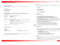
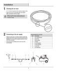
perma-tec GmbH & Co. KG perma MP – 6 perma-tec GmbH & Co. KG perma MP – 6 This operating manual is valid for the distributor perma MP – 6. ©Konzeption & Gestaltung Arbeitssicherheit und Dokumentation ARA, 48167 Münster, www.ara-muenster.de Operating Instructions MP – 6 © 2003 perma-tec GmbH & Co. KG Without the specific approval of perma-tec GmbH & Co. KG no part of this documentation can be copied or made available to third parties. We have taken great care when compiling all the details contained in this documentation. However, we cannot rule out discrepancies and we reserve the right to make technical changes to the product without giving advance notice. We do not assume any judicial responsibility or liability for damages which may ensue as a result. We will include any necessary changes in the next edition. Compiled and printed: Lubrication Systems Lubrication Systems 28 / 11 / 2005 perma-tec GmbH & Co. KG The Distributor perma MP – 6 Housing contains the piston with its bores and the coding disk. Outlets 1 to 3 with connecting pieces for attaching the lubricant tubes. Quick Reference Guide for the Distributor perma MP – 6 On this page you will find some important information for quick and easy operation and setting of your perma MP – 6 distributor. Before the perma MP – 6 is used, prior to the assembly of the distributor with a lubricator of the perma PRO range and whenever you need detailed information, you should read the complete Operating Instructions, which contain information that must be observed. Make sure to follow the instructions given in the chapter “Safety Instructions“. Additionally, you have to observe the Operating Instructions of the connected lubricator. Connection thread for attaching a lubricator of the perma PRO line. Outlets 4 to 6 with connecting pieces for attaching the lubricant tubes. Assembly of the perma MP – 6 (refer to chapter 4.1 and 4.2) ♦ Drive unit contains the motor and the electronics. ♦ ♦ Connector (shown with its protective cap) used for plugging in the connecting cable. Attach the connecting pieces to the outlets that are to be opened and seal the other outlets with the plugs. Insert the coding pins into the coding disk according to the position numbers of the open outlets. A coding pin is already pre-assembled in position 1. Place the housing on the drive unit and screw the two parts together. Screw together the perma MP – 6 with the Lubricator (refer to chapter 4.3) Accessories Coding pins (8 pcs.) are inserted into the coding disk to mark the open outlets. Connecting cable (1 pcs.) used for power supply and for communication. ♦ Seal the connection thread with a suitable, conventional sealant. ♦ Screw the perma PRO lubricator tightly into the thread of the distributor. ♦ Position the rear sides of the lubricator and the distributor at one level. ♦ Attach the distributor and the lubricator to the mounting device and fix it using the four bores. ♦ Connect the lubricant tubes (Ø 8 x 1.5, inner-Ø 5mm, admissible total length per pipe up to 5 m) to the connecting pieces of the distributor and lay them between the distributor and the lubrication point. ♦ Connect the lubricator with the distributor using the enclosed connecting cable. For this, the lubrication system must be switched off. Connecting piece (6 pcs.) for attaching the lubricant tubes. Plug (4 pcs.) for sealing the outlets that are not used. Housing with Coding Disk and Coding Pins Determine the Discharge Period (refer to chapter 5.7) ♦ Housing with coding disk. Bores 1 to 6 of the coding disk where the coding pins are inserted. ♦ ♦ ♦ Piston with bores for the individual outlets. Starting the Complete Lubrication System (refer to chapter 5.5) ♦ Keep the ON/OFF/SELECT button of the lubricator PRO pressed until the display no longer shows "––" (for OFF). To start the lubrication system PRO C switch on power supply. ♦ An automatic initialization is carried out by the lubrication system and the display shows the counting of the open outlets. ♦ After the initialization is complete, the display of the lubricator shows the remaining volume and the lubrication system starts to operate. Coding disk into which the coding pins are inserted.. Coding pin marks an outlet as open. Lubrication Systems Determine the required lubricant volume (cc) per one hundred operating hours while taking into account the number of open outlets. For this, you have to multiply the lubricant volume with the number of open outlets. You have to take into account that this distributor is able to supply an equal amount of lubricant to up to six lubrication points. Determine the required discharge volume using the Operating Instructions of the lubricator. Depending on the size of the PRO LC-unit you can then determine the setting of the discharge period and the setting mode. You may also refer to our perma SELECT program which can be downloaded from our web page free of charge. It helps you in selecting the correct settings. 1 2 perma-tec GmbH & Co. KG perma MP – 6 perma MP – 6 Table of Contents The distributor perma MP – 6 1 Quick Reference Guide 2 Content 3 1. Miscellaneous 1.1 Delivery / Content 1.2 Markings 1.3 Intended Usage 1.4 Legal Requirements 4 2. Safety Instructions 2.1 Persons Responsible for Safety 2.2 General Safety Instructions 2.3 Safety Information for perma MP – 6 6 3. Technical Data 3.1 Design of the perma MP – 6 Distributor 7 4. Assembly and Mounting of the Distributor 4.1 Mounting the Connecting Pieces 4.2 Inserting or removing the Coding Pins 4.3 Combination of Distributor and Lubricator 9 5. Operation and Control 5.1 Preparations 5.2 Prior to Operation 5.3 Setting into Operation 5.4 During Operation 5.5 Switching the Complete Lubrication System On 5.6 Switching the Complete Lubrication System Off 5.7 Determining the Discharge Period 5.8 Setting the Discharge Period 5.9 Initialization of the Distributor 12 6. Trouble Shooting 6.1 Error Messages of the Distributor on the Display of the Lubricator 6.2 Trouble Shooting Guide 16 7. Accessories and Spare Parts 17 8. Disposal 18 9. Service 18 10. Conformity Declaration for perma MP – 6 20 Lubrication System Consisting of Distributor and Lubricator 21 perma-tec GmbH & Co. KG Hammelburger Str. 21 D-97717 Euerdorf Internet: www.perma-tec.com e-mail: [email protected] Schmiersysteme Lubrication System 26 3 perma-tec GmbH & Co. KG 1. perma MP – 6 Miscellaneous Lubrication system consisting of a perma MP – 6 distributor and a lubricator of the PRO line About this Operating Manual ♦ ♦ ♦ ♦ This operating manual is intended for the safe operation of the perma MP – 6 distributor. It contains safety instructions which must be adhered to. Everyone who works on or with the perma MP – 6 distributor must have access to this operating manual during their shift. They must also pay attention to all relevant instructions and notices. The operating manual must always be kept complete and in easy to read condition. In addition, the operating manual of the connected lubricator must be observed. Terms Used ♦ Distributor perma MP – 6 In the following text, the “distributor perma MP – 6“ will either be called “distributor” or by its name “perma MP – 6“. ♦ Lubricator of the perma PRO Line In the following text, the “lubricator of the perma PRO line“ will be called “lubricator“. ♦ Coding Pins / Coding Disk In the following text, a “pin“ for the detection of the outlets in the perma MP – 6 distributor will be called “coding pin“. The “disk“ into which the coding pins are inserted, will be called “coding disk“. Usage of Safety Instructions All safety instructions in this operating manual are standardized. Danger Signs This sign warns you of any danger to people’s health or to subjects. Tips This sign alerts you to application tips which will help you in doing certain tasks quicker and safer. 1.1 Delivery / Content ♦ ♦ ♦ ♦ ♦ ♦ ♦ ♦ ♦ The perma MP – 6 is a distributor for the lubricators of the perma PRO line. The distributor is equipped with all necessary components and accessories and can be set and fitted according to customer requirements. Six optional connecting pieces (G 1/8 straight / G 1/8 90° for tubes Ø 8 x 1.5). Eight coding pins (red), one of them is pre-assembled at position 1 of the coding disk. Four plugs. One cable for connecting the perma MP – 6 distributor to the lubricator. Screws for mounting the distributor. Operating Instructions and EC Conformity declaration. Upon delivery, make sure to check if the delivered goods correspond to your order. perma-tec GmbH & Co. KG will not accept liability for subsequent claims of any shortcomings. Please immediately forward any claims: of noticeable transport damage: directly to the forwarder. of noticeable faults, shortcomings or defects: directly to your local supplier. Lubrication Systems 4 21 perma-tec GmbH & Co. KG 10. perma MP – 6 Conformity Declaration for perma MP – 6 1.2 Markings EC – Conformity Declaration ♦ The perma MP – 6 distributor is clearly marked with a serial number and a label on the drive unit. According to the Machinery Directive 98/37/EC and according to EMV (Electromagnetic Compatibility) – Directive 89/336/EWG. ♦ CE mark on the drive unit. ♦ Manufacturer: The manufacturer perma-tec GmbH & Co. KG Hammelburger Straße 21 97717 Euerdorf, Germany perma-tec GmbH & Co. KG Hammelburger Straße 21 D – 97717 Euerdorf Internet: e–mail: hereby declares that the product as described in the given statement conforms to the regulations appertaining to the directives referred to above, including any amendments thereto which are in force at the time of the declaration. Product description: Product name: Type: 1.3 www.perma-tec.com [email protected] Intended Usage The distributor perma MP – 6 Distributor for lubricators of the PRO line Distributor perma MP – 6 perma MP – 6 ♦ ♦ ♦ The following harmonized standards were applied: ♦ EN 292 – 1: 1991 Safety of machinery – basic concepts, general terms of reference as regards design and construction – Section 1: Basic Terminology, Methodology EN 292 – 2:1991 Safety of machinery – basic concepts, general terms of reference as regards design and construction – Section 2: Technical terms of reference and specifications ♦ ♦ ♦ ♦ ♦ ♦ ♦ EN 60204 – 1:1998 Machinery’s electrical equipment May only be used together with a lubricator of the perma PRO line. Must be connected to the lubricator using the supplied connecting cable. Immediately supplies up to six lubrication points with lubricant, at a pressure build-up of max. 25 bar (360 psi), constantly, precisely and independent of temperature. Can be used for all lubrication points of sliding- and roller bearings, drive- and transport chains, sliding guideways, open gears and seals. May only be used at lubrication points of the same type, which require identical discharge volumes. May only be fitted with original connecting pieces, plugs and coding pins from perma-tec. May only be used with original lubrication tubes from perma-tec. Is intended for use on machinery and equipment. Is only to be used for the intended purpose and purposes confirmed by perma-tec. Is only to be used for operating conditions recommended in this operating manual. Is only to be used with settings and variations recommended in this operating manual. Any other usage, setting, addition, and variation is considered to be inappropriate! 1.4 Euerdorf, 04 January 2003 Legal Requirements Liability perma-tec GmbH & Co. KG ♦ Peter Mayr, Managing Director ♦ Dr. Michael Weigand, Technical Management This declaration certifies conformity to the directives referred to but it is not a warranty of qualities. The safety instructions of the operating manual are to be observed.. The information, data and tips stated in this operating manual were up-to-date as of the printing date. No claims for already delivered distributors perma MP – 6 can be made based on the information, pictures and descriptions. perma-tec GmbH & Co. KG can not be held liable for damages and malfunctions caused by: inappropriate usage unauthorized alterations to the distributor inappropriate operations on or with the distributor incorrect operation and settings of the distributor incorrect settings of time and size of the complete lubrication system ignoring the operating manual of the distributor or the lubricator Warranty ♦ ♦ ♦ Lubrication Systems 20 5 Warranty terms and conditions: see terms and conditions of sale and delivery appertaining to permatec GmbH & Co. KG. Lodge any warranty claims with your local supplier immediately after the defect or error has been identified. The warranty expires in all instances where no liability claims can be enforced. perma-tec GmbH & Co. KG 2. Safety Instructions 2.1 Persons Responsible for Safety ♦ 2.2 Notes: The operator or his safety officer must warrant, that all the relevant regulations, instructions and laws are adhered to; that only qualified personnel will work with and on the distributor; that unauthorized personnel are not allowed to work with and on the distributor; that the safety regulations are adhered to when mounting the distributor or during maintenance. General Safety Instructions ♦ ♦ ♦ ♦ ♦ ♦ ♦ ♦ 2.3 perma MP – 6 We are not laying claim to completeness as regards these safety instructions. Please contact perma-tec Customer Service if you have any queries or problems. At the time of delivery the lubricator is in line with state-of-the-art technology and in principle is considered to be safe to operate. The distributor may only be used with a lubricator of the perma PRO line. Dangers emanate from the distributor perma MP – 6 for persons, the distributor itself, the lubricator and for other material assets of the operator if: unqualified personnel operates the distributor; the distributor is used inappropriately and for operations that it was not intended to be used for; the distributor setting / variation is incorrect; the distributor is opened by force while in operation; the distributor is not mounted with the perma mounting device and the lubricator; the tube connection to the lubrication point was not carried out and attached correctly. Operate the distributor only when it is in perfect condition. Retrofitting, changing, or reconstructing the distributor is not allowed. perma-tec must be consulted first. Only original tube connections and connectors from perma-tec can be used on or with the distributor since these will withhold high pressures of up to 25 bar (360psi.). Ambient media, especially chemically aggressive substances, can attack seals and plastic. Safety Information for perma MP – 6 Safety during Installation and Maintenance ♦ ♦ ♦ Ensure that all workstations and traffic routes are clean and safe! Ensure that the relevant regulations and guidelines are adhered to when the installation or maintenance work is carried out in places where danger of falling exists. Ensure that the relevant safety and operating instructions are observed when the lubricators and distributors are installed or serviced on machines or in factories (i.e. to stop the machine). Safety When Handling Lubricants ♦ ♦ ♦ ♦ ♦ Avoid contact of lubricant with eyes, skin, and clothing! Avoid swallowing of lubricant! Prevent lubricant from getting into soil or sewer system! Observe safety data sheets of lubricants! Lubricant on traffic ways will increase the danger of slipping! Therefore, immediately clean lubricant from floors with special cleaner! Lubrication Systems 6 19 perma-tec GmbH & Co. KG perma MP – 6 3. 8. Technical Data Disposal Distributor perma MP – 6 Help us in protecting the environment and saving resources by recycling valuable raw material. Please follow the individual waste disposal regulations in your country. 9. Length 148 mm Diameter 64 mm Weight ca. 0.960 kg Number of outlets 2 minimum Service 6 maximum ♦ If you wish to return a perma MP – 6 that is no longer used, please check with your local supplier for possible return to recycle or dispose of the used parts in an environmentally safe manner. Maximum working pressure 25 bar (360 psi) Lubricants Greases up to rated consistency NLGI2 Ambient temperature -20° C to +60° C / -4° F to +140° F Power supply from the lubricator via connecting cable Connection thread for lubricators of the PRO line G 3/8 inside Connection thread for lubricant tube G 1/8 inside Diameter of lubricant tube 8 x 1.5 (inner-Ø 5mm) admissible total length per pipe up to 5 m. For details please regard operating manual PRO/PRO C, chapter 3, page 7 Length of the lubricant tube Storage conditions Dry, dust-free at temperatures of +20° C ± 5° C / 68° F ± 9° F Protection class IP 54 148 G 1/8 Table 1 max. Ø 64 38 sw 19 G 3/8 inside Figure 1 Lubrication Systems 18 7 perma-tec GmbH & Co. KG 3.1 perma MP – 6 Design of the perma MP – 6 Distributor 7. Distributors (refer to figure 2) are supplied without factory-settings, but with all the necessary accessories (refer to figure 3). The operator has to install the required connecting pieces or plugs and the necessary coding pins and he also has to connect the distributor to a lubricator of the perma PRO line. The perma MP – 6 distributor consists of: Accessories and Spare Parts Due to the high pressure of up to 25 bar (360 psi), you should only use genuine spare parts and accessories from perma-tec in order to ensure a reliable operation of the distributor and the complete lubrication system. This especially applies to connecting pieces and lubricant tubes. Spare parts and accessories must meet the technical requirements! This is always guaranteed with genuine spare parts and accessories from perma-tec. Spare parts Distributor perma MP – 6 Art. No. 2291 000 000 Housing containing the piston with its bores and the coding disk into which the coding pins can be inserted. Drive unit containing the motor and the electronic unit. Straight connecting piece G 1/8 for lubricant tubes 27.008.010 Plug 70.613.007 Angle G 1/8 for connecting a lubricant tube 27.008.011 Coding pin 70.626.001 Special lubricant tube (Ø 8 x 1.5, inner-Ø 5mm) with different lengths 27.008.009 Figure 2 Accessories Coding pins (6 pcs., plus 2 spare pins; one of them is pre-assembled in position 1) are inserted in the coding disk for the detection of the open outlets, re-usable. Connecting pieces (6 pcs.) for connecting lubricant tubes to open outlets, re-usable. Connecting cable (short) 2291 000 001 Connecting cable (length: 2m) 2291 000 002 perma PRO mounting device 27.008.007 400 g grease cartridge for pre-lubrication with grease press filled with SF 04 on request 400 g grease cartridge for pre-lubrication with grease press filled with other lubricants on request Plugs (4 pcs.) for sealing the outlets which are not used, re-usable. Connecting cable (short) for the power supply of the distributor and for communication between distributor and lubricator. Table 3 Figure 3 Lubrication Systems 8 17 Illustration perma-tec GmbH & Co. KG perma MP – 6 6. Trouble Shooting 6.1 Error Messages of the Distributor on the Display of the Lubricator 4. Assembly and Mounting of the Distributor 4.1 Mounting the Connecting Pieces Possible errors of the distributor and the complete lubrication system are detected by the electronic control unit and are indicated on the display of the lubricator. For example, if the error message F2 is shown on the display, the required pressure at the second connected lubrication point exceeds 25 bar (360psi). This means that this lubrication point is no longer supplied with lubricant. The distributor still provides lubricant to all other activated lubrication points . This means that you have to correct the problem at the second activated lubrication point (e.g. tube bent or blocked) and acknowledge the error message by pushing the ON/OFF/SELECT button of the lubricator. Error messages are acknowledged and reset by pushing the ON/OFF/SELECT button. ♦ ♦ ♦ Chose the number (6 max.) and the position of the outlets that you intend to use. Screw the connecting pieces tightly (max. torque of 2Nm) into the outlets to be opened (refer to figure 4). Seal all the remaining outlets using the enclosed plugs. With the error messages F I to F6 you have to bear in mind that the error number F I shown on the display always refers to the first open outlet. This means that error number F I on the display may well point to outlet No. 2 if outlet No. 2 is the first outlet that is open. Therefore, the counting of the outlets starts with that outlet. If outlets Nos. 2 and 4 are open, error message F I means that outlets No. 2 is concerned and F2 is referring to outlet No.4. The numbers of the errors messages always point out to the order of the outlets that are really open. 6.2 1 4 2 5 3 6 Trouble Shooting Guide If there are malfunctions during the operation of the distributor or the lubrication system, please check for possible causes using the following table (refer to table 2). If you have to deal with a malfunction that is not listed in the table below, please contact your local supplier for technical support. Figure 4 4.2 The continuous numbering of the outlets from one to six on the housing of the distributor corresponds to the numbering on the coding disk. Therefore, the outlets correspond to the inserted coding pins. This means that if you want to open the outlets No. 1, 3 and 5, coding pins must also be inserted into the positions No. 1, 3 and 5 of the coding disk. The other bores remain empty and are not fitted with coding pins. Please bear in mind that a coding pin is already pre-assembled in position 1 of the coding disk. If you do not want to open outlet No. 1, you can remove this pin and insert it at another position. Every time that an error message is shown on the display of the lubricator, the red LED at the lubricator is also blinking. Display shows EO F I to F6 Malfunction Possible cause Corrective Action Lubrication system has been switched off Excess motor current of the perma MP – 6 Replace perma MP – 6 distributor Error at the displayed lubrication point Excess motor current of the lubricator motor caused by a blocking of the displayed outlet Clear the blockage and acknowledge the fault by pushing and holding down the ON/OFF/SELECT button E2 Lubrication system has been switched off Drive mechanism of the distributor is defective Check the coding pins and carry out an initialization E3 Lubrication system has been switched off perma MP – 6 does not detect the coding pins Check the distributor and the coding pins E4 Lubrication system has been switched off Drive mechanism of the lubricator is defective Replace the drive unit of the lubricator LC Lubrication system does not detect the PRO LC-unit No PRO LC-unit installed Install an PRO LC-unit (Observe the Operating Instructions of the lubricator) Signal of the jumper is not found Jumper has not been inserted correctly or is missing Insert the jumper in the correct slot for the PRO LCunit that you intend to use (Observe the Operating Instructions of the lubricator) No power supplied to the lubrication system No power supplied to the lubricator Establish a power supply (Observe the Operating Instructions of the lubricator) Lo Inserting or removing the Coding Pins The lubrication system is only able to detect the open outlets during initialization and to ensure their provision with lubricant if the numbering of the open outlets corresponds to the inserted coding pins. ♦ ♦ ♦ ♦ Unscrew the two Allen screws (M4 x 70) at the lower part of the drive unit (refer to figure 5). Take off the housing from the drive unit to be able to reach the coding disk. Insert the coding pins according to the open outlets into the corresponding bores of the coding disk (refer to figure 5). For this, you simply have to insert the coding pins and since they are clip-on pins you can also remove them easily again. Make sure to hold on to the coding disk when removing the pin so you do not accidentally pull the piston out of the housing. Place the housing on the drive – making sure to place the hexagon of the piston into the hexagon of the drive unit. Screw both parts together again. Place the housing on the drive unit and screw the two parts together again. Observe the maximum torque of 2 Nm for the Allen screws M4 x 70. 2 Allen screws M4 x 70, maximum torque 2 Nm Piston Coding pin Coding disk Table 2 Figure 5 Lubrication Systems 16 9 Hexagon of piston perma-tec GmbH & Co. KG 4.3 perma MP – 6 Combination of Distributor and Lubricator 5.9 After you have fitted, set and assembled the perma MP – 6, you can combine the distributor and a lubricator of the PRO line to form a lubrication system. Automatic Initialization of the Distributor Screw the distributor and the lubricator together. Attach both to the perma mounting device and install the mounting device. In order to supply lubricant to all open outlets and to ensure a correct operation of the perma MP – 6, an automatic initialization of the lubrication system is carried out when the system is switched on for the first time. During initialization, the number of coding pins is checked and read in by the connected lubricator. The display counts the inserted coding pins and not their numerical position. The number of the inserted coding pins must correspond to the number of open outlets and to the number shown on the display of the lubricator. Direct Mounting of the Distributor onto the Lubricator ♦ ♦ ♦ ♦ ♦ ♦ ♦ ♦ ♦ ♦ Initialization of the Distributor Before you combine the distributor and the lubricator, the distributor, the lubrication points and the complete lubricant tubes must be pre-lubricated with the same lubricant that the PRO LC-unit of the lubricator contains. For that, perma-tec offers a 400 g lubrication cartridge for manually-operated grease presses with the requested lubricant. Additionally, seal the connection thread of the lubricator with a suitable conventional sealant. Screw the lubricator tightly into the G 3/8 thread of the distributor. Position the rear sides of the lubricator and the distributor at one level. Attach the supplied mounting device to the distributor and the lubricator using the enclosed hex head bolts (M6 x 16) and the washers. Screw the mounting device together with the lubrication system onto a support of your system. For the position of the bores of the four fixing screws refer to figure 6 below. You have to use four hexagon screws M6 x 25 (e.g. on metal ground). Connect the lubricant tubes to the connecting pieces of the distributor and install the tubes correctly between the distributor and the lubrication point. Tube length may not exceed five meters per outlet. Attach the required connecting pieces to the ends of the lubricant tubes. While the lubrication system is switched off connect the lubricator to the distributor with the enclosed connecting cable. The lubrication system is now ready for operation. When the automatic initialization is complete, the display of the lubricator shows the remaining volume and the lubrication system starts to operate. Manual Initialization of the Distributor If you have changed the number or the position of the outlets of the lubrication system consisting of the PRO lubricator and the distributor, or if you have mounted a completely new distributor, you have to carry out a manual initialization of the perma MP – 6. If you want to check the number of open outlets, you can also carry out a manual initialization. The manual initialization is only possible if the lubrication system is switched off (display "–– " for OFF on the display of the lubricator) and if you press and hold down both buttons of the lubricator simultaneously (refer to figure 11). During initialization, the number of coding pins is checked and read in by the connected lubricator. The display of the lubricator counts the number of the inserted coding pins and not their numerical position. The number of the inserted coding pins must correspond to the number of the open outlets and to the number shown on the display of the lubricator. Ensure correct and tight assembly of the connections and lubricant tubes to avoid possible leakage. MODE SAVE 2 hex head bolts M6 x 16, maximum torque 3 Nm (for attaching the lubricator to the mounting device) Lubricator PRO C When the manual initialization is completed, the display of the lubricator PRO C shows the remaining volume of the PRO LC-Unit and the lubrication system is switched on. 2 hex head bolts M6 x 16, maximum torque 3 Nm (for attaching the distributor to the mounting device) 45 2 hexagon screws M6 x 25 (for wall mounting on metal) Figure 6 Lubrication Systems For a manual initialization, press and hold down both buttons of the lubricator simultaneously. Lubricator PRO When the manual initialization is completed, the display of the lubricator PRO shows "––" for OFF and the lubrication system is switched off. 2 hexagon screws M6 x 25 (for wall mounting on metall) 75 351,5 (for lubricators with 250 cc PRO LC.unitt) 402, for lubricators with 500 cc PRO LC.unit) Figure 11 ON/OFF SELECT 10 15 perma-tec GmbH & Co. KG 5.8 perma MP – 6 Setting the Discharge Period Separate Mounting of Distributor and Lubricator The discharge period can be set any time via the lubricator and without having to interrupt the operation. It does not matter if the lubrication system is switched on or off, since the system switches back to its original operating status after the changes have been made. For a precise setting of the discharge period, please refer to the Operating Instructions of the connected perma PRO lubricator. Separate mounting of the distributor and the lubricator is possible. For this, perma-tec offers an additional mounting device, the necessary tube connections and a longer connecting cable (refer to chapter 7). Attach the lubricator of the PRO line to your system as described in its Operating Instructions and mount the distributor as follows: Additional Discharge ♦ With an additional discharge, all open lubrication points can be supplied with an additional amount of the lubricant. Each open outlet provides 1.0 cc of the lubricant. ♦ For an additional discharge, the lubrication system must be switched on and you have to press and hold down both buttons of the lubricator simultaneously (refer to figure 10). An additional discharge is carried out for all outlets marked by coding pins at an interval of approx. 30 seconds between two outlets. This means that if all outlets are open, the process of an additional discharge takes maximum 14 minutes. ♦ MODE SAVE Figure 10 ♦ ♦ ON/OFF SELECT ♦ For an additional discharge, press both buttons of the lubricator and hold them down. An additional discharge is only possible at temperatures above 0° C (32°F). Every additional discharge reduces the remaining discharge period since an increased amount of the lubricant has been supplied. This must be taken into account in your lubrication and maintenance schedule. ♦ ♦ ♦ The minimum period between two additional discharges is 30 seconds. If you continue to press the buttons during that period, further additional discharges for all outlets will follow. Attach the mounting device to the distributor using the enclosed hex head bolts (M6 x 16) and the washers. Screw the mounting device with the distributor onto a support of your system. For the bore position of the four fixing screws refer to figure 7 below. At least four hexagon screws M6 x 25 must be used (e.g. on metal ground). Before you connect the outlets of the distributor to the lubricant tubes, you have to make sure that the distributor, the lubrication points and all lubricant tubes are pre-lubricated with the same lubricant that is contained in the PRO LC-unit of the lubricator. For that, perma-tec offers a 400 g lubrication cartridge for manually-operated grease presses with the requested lubricant. Fit the straight G 1/8 tube connection (Art. No. 27.008.010) on the lubricator and fit the G 3/8 tube connection (Art. No. 27.008.013) on the distributor (max. torque 2 Nm). Connect the distributor to the PRO lubricator with the lubricant tube. Maximum tube length 2 meters (Ø 8 x 1.5, inner-Ø 5mm). Connect the lubricant tubes to the connecting pieces of the distributor and install them correctly between the distributor and the lubrication point. The lubricant tube between the lubricator and the lubrication point cannot exceed a total length of 5 meters (for details re. temperature and lubricant please regard operating manual PRO/PRO C, chapter 3, page 7)! Fit the ends of the lubricant tubes with the required tube connecting pieces. While the lubrication system is switched off, connect the lubricator to the distributor with the connecting cable (long). The lubrication system is now ready for operation. Ensure correct and tight assembly of the connections and lubricant tubes to avoid possible leakage. 45 Calculation of the Remaining Discharge Period 2 hex head bolts M6 x 16, maximum torque 3 Nm (for attaching the distributor to the mounting device) 2 hexagon screws M6 x 25 (for wall mounting on metal) Figure 7 Lubrication Systems 14 11 75 2 hexagon screws M6 x 25 (for wall mounting on metal) Please note, that in case of one or several additional discharges, the remaining discharge period of the lubrication system must be recalculated. This also applies in case of a shut-off of the lubrication system due to an extended machine standstill (e.g. weekends or annual holidays) or in case of a low-temperature shut-off carried out by the system if temperatures reach -20° C (-4°F). For information on the calculation of the remaining discharge period, please refer to the Operating Instructions of the connected perma PRO lubricator. You should also note the result of your calculation of the remaining discharge period in your lubrication and maintenance schedule. perma-tec GmbH & Co. KG 5. perma MP – 6 5.4 Operation and Control ♦ Please note that the perma MP – 6 distributor may only be connected to a lubricator of the PRO line. If you combine the distributor with a PRO lubricator, you also have to observe the Operating Instructions of the lubricator. 5.1 Preparations ♦ ♦ ♦ ♦ ♦ ♦ ♦ Prior to the installation of the lubrication system consisting of the distributor and the lubricator, the distributor, the lubrication points and all supply tubes must be sufficiently pre-lubricated with the same lubricant that the PRO LC-unit of the lubricator contains. For this, perma-tec offers a 400 g lubrication cartridge for grease presses with the corresponding lubricant (refer to table 3, chapter 7). When installing the lubrication system, the supplied perma-tec mounting device should be used. The lubricator and the distributor should be fixed to this mounting device (refer to chapter 4.3). The lubricant tubes must be installed and mounted correctly. Lubricant tubes must be from perma-tec and cannot exceed a length of 5 meters per outlet. For the initial setting into operation of a perma PRO lubricator, the pump system in the drive unit is pre-filled with SF 04 from perma’s standard range of lubricants. An exception is made with regard to lubricants for the food industry. A complete discharge of this pump filling is guaranteed after approx. 10 discharges (carry out additional discharges, if necessary). 5.2 ♦ ♦ ♦ ♦ ♦ 5.5 ♦ ♦ ♦ ♦ ♦ ♦ ♦ ♦ Switching the Complete Lubrication System On To switch on the lubrication system PRO (refer to figure 8), keep the ON/OFF/SELECT button of the lubricator pressed until the display no longer shows "–– ". To start the lubrication system PRO C you have to switch on power supply. The lubricator automatically carries out an initialization. For this, the system counts the inserted coding pins and the display shows the number of the open outlets (not the outlet number). When the initialization is complete, the display of the lubricator shows the remaining discharge volume and the green LED starts blinking. Check all parts of the distributor and the complete lubrication system for obvious damages! Did you correctly assemble, mount, and tighten all of the connecting pieces and the plugs of the distributor? Are the lubricant tubes coming from the distributor mounted correctly on the connecting pieces? Did you insert the coding pins correctly into the coding disk? Did the lubricator recognize the distributor with all open outlets during initialization? Was the drive unit of the lubricator set to the discharge period requested by the operator while taking into account the required discharge volume and the number of open outlets? Did you correctly assemble, mount and tighten all of the parts? –– 6 ON/OFF SELECT The lubrication system is switched off. 99 The initialization is carried out and the number of the open outlets (max. 6) is indicated. The lubrication system is on. When the lubrication system is switched on for the first time, the initialization is carried out automatically by the lubricator. Only after the initialization is complete, the remaining volume is shown. Open the required number of outlets by mounting the connecting pieces and seal the unused outlets with plugs (refer to chapter 4.1). Insert the coding pins according to the open outlets (refer to chapter 4.2). Screw together the distributor and the lubricator (refer to chapter 4.3). If required, mount the distributor together with the lubricator onto the mounting device and onto a fixing device for wall-mounting (refer to chapter 4.3). Connect the distributor to the lubricator with the connecting cable to enable signal exchange (refer to chapter 4.3). If necessary, carry out a manual initialization (refer to chapter 5.9). Determine the discharge period for the open outlets (refer to chapter 5.7). Set the discharge period via the buttons of the lubricator. Carry out an additional discharge (refer to chapter 5.8). If the drive motor has started and the green LED is lit, the lubricator has started to discharge. The display of the lubricator indicates the remaining volume (% Vol.) of the PRO LC-unit. The operator must always check the customer-specific settings and if necessary change them before the lubricator is set into operation! In addition, the Operating Instructions of the lubricator must be observed. 5.6 Switching the Complete Lubrication System Off To switch off the lubrication system PRO (refer to figure 9), keep the ON/OFF/SELECT button of the lubricator pressed until the display no longer indicates the remaining volume but indicates "–– " instead. To stop the lubrication system PRO C you only have to switch on power supply. When the lubrication system is switched off, all of the settings are saved. This means that if you start the lubricator again, it will take up operation at the point where it had been switched off. 99 % Vol. ON/OFF SELECT –– Figure 9 5.7 Determining the Discharge Period The required discharge period must be determined using the Operating Instructions of the connected lubricator. You have to take into account that the distributor perma MP – 6 is able to supply an equal amount of lubricant to up six lubrication points. When determining the discharge volume, you have to multiply the number of open outlets with the required discharge volume per outlet. With the result of this calculation you can determine the setting point of the discharge period using the Operating Instructions of the connected lubricator. Lubrication Systems % Vol. Figure 8 Setting into Operation ♦ Carry out regular inspections during operation. You should pay special attention to leakage, to the condition of the distributor, and the complete lubrication system! Regularly check the condition of the lubricant tubes and the connections! Regularly check the filling level of the transparent PRO LC-unit of the lubricator! After one or several additional discharges, you have to calculate the remaining discharge period and mark it in your lubrication and maintenance schedule. If a malfunction is indicated on the display, you can determine the cause using the trouble shooting guide (refer to table 2, chapter 6.2). If the fault cannot be fixed, please contact your supplier for technical support. Additional discharges and long machine standstills must always be taken into account with regard to the remaining discharge period of the lubrication system. Prior to Operation ♦ ♦ 5.3 During Operation 12 13