1
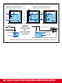
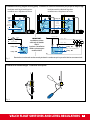
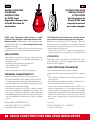
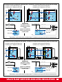
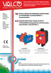
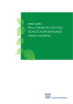
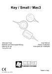
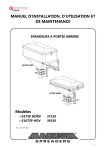
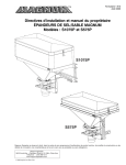
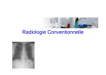
PUMPS, MOTORS and CONTROLS MANUFACTURING
FABRICATION DE POMPES, MOTEURS ET DISPOSITIFS DE
CONTROLE ET DE NIVEAU
VALCO
Established
in Marostica,
Italy, since 1976
worldwide
VALCO
Etablie à
Marostica, Italie,
depuis le 1976
et avec présence
mondiale
INSTALLATION AND OPERATING INSTRUCTIONS
for VMS-C and PCMF Level Regulators
INSTRUCTIONS POUR L’INSTALLATION ET L’UTILISATION
des Régulateurs de Niveau VMS-C et PCMF
Counterweight
provided on
request
Contrepoids
fourni sur
demande
Made in Italy
Fabriqué en Italie
VMS-C
Microswitch Level
Regulators - Float Switches
Régulateurs de Niveau à
microswitch
PCMF
Level Regulators
Mercury-free to RoHS
Directive for wastewater
Règulateurs de Niveau sans
ampoule à mercure pour
eaux chargées
VALCO
Works, Pump & Motor Test Laboratory, Pumps and Electric Motors Research Centre.
Usine, Laboratoire Essais, Centre de Recherche Pompes et Moteurs.
INSTALLATION AND
OPERATING
INSTRUCTIONS
for VMS-C
Microswitch Level
Regulators
INSTRUCTIONS POUR
L’INSTALLATION ET
L’UTILISATION
des Régulateurs de
Niveau à microswitch
VMS-C
VMS-C Microswitch Level Regulators
The appliance combined with a pump connected by
a flexible cable, permits the regulation of the level of
the liquid in which it is immersed. The regulator in fact
features a float with a totally waterproof casing, inside
which there is a microswitch connected to the cable.
The float position depends on the liquid level and determines the commutation of the microswitch which
in turn controls the pump operation.
VMS-C Régulateur de Niveau à microswitch
Le dispositif accouplé à une pompe par un câble flexible
permet de régler le niveau du liquide dans lequel il est
placé. Chaque régulateur se compose en effet d’un carter
flottant entièrement étanche, à l’intérieur duquel se trouve
un microcontact relié au câble flexible. La position prise
par le flotteur, en fonction du niveau du liquide, détermine
la commutation du microcontact en commandant l’actionnement de la pompe.
INSTALLATION
INSTALLATION
To ensure the efficient function of the appliance it is
necessary to fix the electric cable inside the tank or well
as illustrated in figures no. 1 and no.2. The length of the
cable section between the fixture point of the same
and the regulator body, determines the total extension
of the float and the consequent distances between
the pump stopping and starting level. It is also necessary to check that the float is not obstructed during
its run. During installation joints to the level regulator
cable must not be made under any circumstances. An
eventual cable joint section must never be immersed
in water.
Pour un fonctionnement correct du dispositif, il faut fixer le
câble électrique à l’intérieur de la cuve ou du puits, comme
indiqué sur les figures 1 et 2. La longueur de la partie de
câble comprise entre le point de fixation et le corps du
régulateur, détermine l’excursion totale du flotteur, et par
conséquent la distance entre le niveau d’arrêt et de démarrage de la pompe. Il faut également contrôler que rien ne
puisse gêner le flotteur durant sa course. Pendant l’installation, il faudra absolument éviter d’effectuer des joints du
câble du régulateur de niveau. En cas de joint éventuel du
câble, celui-ci ne devra pas toucher l’eau.
COUNTERWEIGHT INSTALLATION IF PRESENT
INSTALLATION DU CONTREPOIDS SI PRESENT
For correct counterweight installation refer to the following procedure as illustrated in figure no. 3.
1. Insert the cable into the counterweight, from the
conical side, turning it. This will result in the detachment of the plastic ring inserted in the mouth (if
necessary aid detachment
by using a screwdriver).
2
Place the ring at the point of the cable where the
counterweight is to be fixed.
2. Fix the counterweight on the ring using moderate
pressure and turning it.
The counterweight is only provided on request.
Pour que l’installation du contrepoids soit correcte, il faut
suivre la procédure illustrée sur la figure 3.
1. Introduire le câble dans le contrepoids, du côté conique,
en le tournant. Ceci provoquera le détachement de
l’anneau en plastique placé à l’embouchure (en cas de
besoin, le détachement peut être facilité avec un tournevis). L’anneau sera placé dans la partie du câble devant
accueillir le contrepoids.
2. Forcer en douceur le contrepoids sur l’anneau, en le tournant.
Le contrepoids n’est fourni que sur demande.
2
VALCO FLOAT SWITCHES AND LEVEL REGULATORS
ELECTRICAL CONNECTIONS
BRANCHEMENTS ELECTRIQUES
The regulator may be used for filling or emptying according to the connections made between the terminals of the microswitch and the cable.
For correct product installation refer to wiring diagrams
in figures no.1-2.
Le régulateur peut être utilisé tout aussi bien pour le remplissage que pour le vidage en fonction des branchements
effectués entre les terminaux du microcontact et le câblage.
Pour une installation correcte, il faut se reporter aux schémas électriques des figures 1-2.
NOTE
When making the connections described above ensure that the maximim motor power does not exceed
the values indicated on the level regulator.
The power supply cable is an integral part of the appliance. Should the cable be found to be damaged the
appliance is to be replaced. Repairs to the cable itself
are not possible.
The earth wire of yellow/green colour must be connected to a suitable earth terminal and the section
dimension must not be less than 1 mm2. The eventual terminal used must be effectively protected
against accidental slackening.
NOTES
Lors des connexions susdites, ne pas oublier de vérifier si
le courant maximum du moteur correspond aux valeurs
indiquées sur le régulateur de niveau.
Le câble d’alimentation fait partie intégrante du dispositif.
Dans le cas où le câble serait abîmé, le
dispositif doit être obligatoirement remplacé; le câble en
effet ne peut pas se réparer.
Le conducteur de terre de couleur jaune/vert doit être
connecté à un bornier de terre adapté et doit
avoir une section non inférieure à 1 mm2. Le bornier
utilisé doit être efficacement protégé contre les desserrements accidentels.
ELECTRICAL FEATURES - CARACTERISTIQUES ELECTRIQUES
MAXIMUM OPERATIONAL TEMPERATURE
50°C
TEMPERATURE D’UTILISATION MAX
IP68 (tested by IMQ at a depth of 1m for a period of 7 days at water
PROTECTION GRADE
temp. of 50°C)
DEGRE DE PROTECTION
IP68 (testé par IMQ à la profondeur de 1 m pendant 7 jours, temp. de
l’eau 50°C.).
The appliances pass an immersion test at depth of 10 m, at a temFACTORY RELIABILITY TEST
perature of 50°C for a period of 7 days.
ESSAI DE FIABILITE
Les dispositifs ont franchi sans problème l’essai de plongée à 10 m de
profondeur, à la température de 50°C. pendant 7 jours.
POLLUTION GRADE
NORMAL
DEGRE DE POLLUTION
NORMALE
FEATURES OF AUTOMATIC ACTION
1B (micro-disconnections in operation)
TYPE D’ACTION/CARACTERISTIQUE
1B (micro connexion en fonctionnement)
The regulators are homologated in compliance with
CEI EN 60730 standards and thereby comply with the
fundamental requisites of Directive 93/68/EEC.
Les régulateurs sont homologués selon les normes CEI EN
60730, et de ce fait sont conformes aux principales réglementations de la directive 93/68/CEE.
VALCO FLOAT SWITCHES AND LEVEL REGULATORS
3
Installation and wiring diagram for emptying pump - Installation et schéma de branchement pour pompe de vidange
Installation with Single level Regulator
Installation avec 1 Régulateur de niveau
Installation with double level Regulator
Installation avec 2 Régulateurs de niveau
Pump
ON
Pump
ON
Level
drop
Niveau
différentiel
Counterweight
Contrepoids
N
M
black
noir
IMPORTANT:
Installation systems
valid only for models
VMS-C
Systèmes d’ installation
valides seulement pour
modèles VMS-C
brown - marron
Pump - ON
Pump - OFF
Fig. 1
Fixing pipe
Tuyau de fixage
Pump
OFF
Pump
OFF
L
Level
drop
Niveau
différentiel
L
black - noir
brown - marron
brown - marron
Pump - ON
Level drop - Niveau différentiel
Pump - OFF
N
The wire that is not be used must be correctly insulated - Le conducteur qui n’est pas utilisé doit être correctement isolé.
4
4
VALCO FLOAT SWITCHES AND LEVEL REGULATORS
Installation and wiring diagram for filling pump - Installation et schéma de branchement pour pompe de remplissage
Installation with Single level Regulator
Installation avec 1 Régulateur de niveau
Installation with double level Regulator
Installation avec 2 Régulateurs de niveau
Pump
OFF
Pump OFF
Level
drop
Niveau
différentiel
Counterweight
Contrepoids
M
black
noir
blue - bleu
N
Pump - OFF
Pump - ON
Fig. 2
Fixing pipe
Tuyau de fixage
Pump ON
Pump
ON
L
Level
drop
Niveau
différentiel
IMPORTANT:
Installation systems
valid only for models
VMS-C
Systèmes d’ installation
valides seulement pour
modèles VMS-C
L
black - noir
blue - bleu
blue - bleu
Pump - OFF
Level drop - Niveau différentiel
Pump - ON
N
The wire that is not be used must be correctly insulated - Le conducteur qui n’est pas utilisé doit être correctement isolé.
Installation of counterweight - Installation contrepoids
1
2
Fig. 3
VALCO FLOAT SWITCHES AND LEVEL REGULATORS
5
INSTALLATION AND
OPERATING
INSTRUCTIONS
for PCMF Level
Regulators Mercury-free
to RoHS Directive for
wastewater
PCMF Level Regulators Mercury-free to RoHS
Directive for wastewater. Submerged float switch.
Water-resistant to 100 m depth, insensitive to humidity and condensation, with new concept electric contacts consisting of:
• Change over 10 A 250 V self-cleaning switch, by each
operation, with a high distance between contacts.
APPLICATIONS
- Regulation of particularly turbulent industrial waters
containing residues of suspended agglomerates, or
of sewer waters.
- for emptying and filling any type of tank
- with turbulent industrial liquids
- with sewage water
- with waters/liquids with solids in suspension
INSTRUCTIONS POUR
L’INSTALLATION ET
L’UTILISATION
des Régulateurs de
Niveau PCMF Sans
ampoule à mercure
pour eaux chargées
PCMF Régulateurs de Niveau sans ampoule à mercure pour eaux chargées pour eaux usees d’egouts.
Régulateur de niveau type PMCF Submergé, étanche à
l’immersion (100 m de profondeur), insensible à l’humidité
et à la condensation, muni de contacts électriques de nouvelle conception constitué par :
• Commutateur 10 A 250 V c.a. à contacts autonettoyants à
chaque manoeuvre et à une grande distance d’ouverture.
UTILISATION
Régulation d’eaux industrielles particulièrement turbulentes contenants des résidus d’agglomerés en suspension
ou pour des eaux d’égouts.
CARACTERISTIQUES TECHNIQUES
• Mercury-free to RoHS Directive for wastewater
The submerged float switch model PCMF consists of:
• A single outer piece in blowmoulded Polyethylene.
• Internal weight fixing the rotation centre (gravity centre) close to the cable connection.
• Self-cleaning contacts 10 A 250 V a.c electric control
switch with high distance between the contacts. The
float switch is filled with closed cells nonhygroscopic
expanded polyurethane, eliminating all air, sealing the
unit and completely surrounding the electric control
6
switch.
• Sans ampoule à mercure pour eaux chargées.
Le régulateur de niveau submergé type PCMF se compose
de :
• Corps extérieur en polyéthyléne soufflé sous pression en
une seule pièce.
• Poids intérieur pour déterminer le point de rotation (barycentre) à proximité de l’entrée du câble.
• Commutateur de commande électrique 10 A 250 V c.a. à
contacts autonettoyants et à une grande distance d’ouverture. A l’intérieur du régulateur s’effectue une injection
de polyuréthanne expansé à cellules fermées non hygroscopiques qui élimine toutes les particules d’air, ferme le
tout et rend le commutateur de commande électrique
étanche.
MAX WORKING TEMPERATURE 55°C
AVAILABLE CABLES: PVC – NEOPRENE
and special cables on request.
T max 55°C
CABLES DISPONIBLES: PVC - NEOPRENE
et autres sur demande.
TECHNICAL CHARACTERISTICS
6
VALCO FLOAT SWITCHES AND LEVEL REGULATORS
Installation and wiring diagram for emptying pump - Installation et schéma de branchement pour pompe de vidange
Installation with Single level Regulator
Installation avec 1 Régulateur de niveau
Installation with double level Regulator
Installation avec 2 Régulateurs de niveau
Pump
ON
Pump
ON
Level
drop
Niveau
différentiel
Level
drop
Niveau
différentiel
Counterweight
Contrepoids
Fixing pipe
Tuyau de fixage
Pump
OFF
Pump
OFF
L
M
brown
marron
black - noir
N
Pump - ON
IMPORTANT:
Installation systems
valid only for models
PCMF
Systèmes d’ installation
valides seulement pour
modèles PCMF
Pump - OFF
L
brown - marron
black - noir
black - noir
Pump - ON
Level drop - Niveau différentiel
Pump - OFF
N
The wire that is not be used must be correctly insulated - Le conducteur qui n’est pas utilisé doit être correctement isolé.
Fig. 4
Installation and wiring diagram for filling pump - Installation et schéma de branchement pour pompe de remplissage
Installation with Single level Regulator
Installation avec 1 Régulateur de niveau
Installation with double level Regulator
Installation avec 2 Régulateurs de niveau
Pump
OFF
Pump OFF
Level
drop
Niveau
différentiel
Level
drop
Niveau
différentiel
Counterweight
Contrepoids
Pump ON
Pump
ON
L
M
brown
marron
blue - bleu
N
Pump - OFF
Pump - ON
Fig. 5
Fixing pipe
Tuyau de fixage
IMPORTANT:
Installation systems
valid only for models
PCMF
Systèmes d’ installation
valides seulement pour
modèles PCMF
L
brown - marron
blue - bleu
blue - bleu
Pump - OFF
Level drop - Niveau différentiel
Pump - ON
N
The wire that is not be used must be correctly insulated - Le conducteur qui n’est pas utilisé doit être correctement isolé.
VALCO FLOAT SWITCHES AND LEVEL REGULATORS
7
Exclusive High-Tech Pumps for Water and other Fluids,
Motors and Controls, in Standard or Custom Designs,
manufacturing of:
- Electric Pumps: Borehole Submersible, Drainage and
Sewage, Surface Centrifugal Close Coupled
- Controls and Fittings for Pumps and Pumping Installations
- Electric Motors (Compact AC Power) in Standard or
Custom Designs
Exclusive High-Tech Pumps for Water and other Fluids,
Motors and Controls.
Pompes exclusives de haute technologie pour eau et
autres fluides, moteurs et dispositifs de contrôle et de niveau en executions standards et spéciales.
VALCO, la gamme la plus vaste et complète de pompes
pour usages domestiques, collectifs, pour l’agriculture, l’industrie, forages, épuisement, assèchement, eaux usées et
chargées, surpression.
Une source et un service fiable pour les pompes et le meteurs électriques: une solution unique, globale, innovative
et compétitive pour le Pompage et le Moteurs.
We also manufacture and supply:
Nous fabriquons aussi:
Sold by VALCO distributor / Authorized VALCO dealer
Vendu par le Distributeur VALCO suivant:
If repairs are required, contact an authorized
VALCO dealer.
Pour Entretien veuillez contacter notre Distributeur VALCO
VALCO® International trademark.
©
water is the future
HEAD OFFICE, WORKS,
PUMP & MOTOR TEST LABORATORY,
PUMP & MOTOR RESEARCH CENTRE
PUMPS & WATER HANDLING UNIVERSITY
Pumps, Motors and Controls Manufacturing
®
VALCO srl
Via dell’Industria, 27-29
I-36063 MAROSTICA (Vicenza)
Veneto, (Venice Region) - EU - Italy
Ph.: +39-0424-77847
Fax: +39-0424-475806
E-Mail:[email protected]
Http://www.valco.eu
Manufacturer of Useful and Valuable Products for Progress, Prosperity and Peace© - All rights reserved. Reproduction even partial not permitted.
Features subject to change – not contractually valid unless specifically authorized by VALCO.
Caractéristiques techniques passibles de changement_photos et descriptifs ne sont pas contractuels au moins que ils ne soient expressément confirmés et authorizés
par écrit par Valco srl.
is a registered trademark of Valco srl. Text by Valco srl. Copyright© 1976-2010 by VALCO srl.
ref. 1.MAINT-VMS-C-PCMF-EN-FR-11-2010rev.0