1
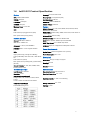
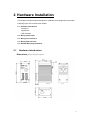
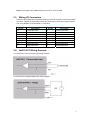
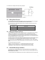
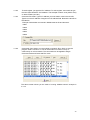
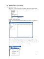
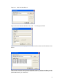
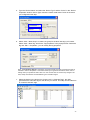
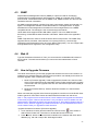
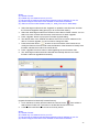
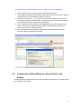
Korenix JetI/O 6511
Industrial Intelligent Ethernet I/O Server
User’s Manual
Dec. 2008 (V1.4)
www.korenix.com
Korenix JetI/O 6511
Industrial Intelligent Ethernet I/O Server
User’s Manual
Copyright Notice
Copyright © 2008 Korenix Technology Co., Ltd.
All rights reserved
Reproduction in any form or by any means without permission is prohibited.
2
Index
1
2
3
4
5
6
INTRODUCTION .............................................................................................................. 1
1.1
OVERVIEW OF JETI/O 6500 SERIES ............................................................................. 1
1.2
PACKAGE CHECKLIST .................................................................................................. 2
1.3
JETI/O 6511 INTRODUCTION ....................................................................................... 2
1.4
JETI/O 6511 PRODUCT SPECIFICATION ........................................................................ 3
HARDWARE INSTALLATION.......................................................................................... 4
2.1
HARDWARE INTRODUCTION ......................................................................................... 4
2.2
WIRING POWER INPUT ................................................................................................ 5
2.3
WIRING I/O CONNECTORS........................................................................................... 6
2.4
JETI/O 6511 WIRING EXAMPLE ................................................................................... 6
2.5
WIRING EARTH GROUND ............................................................................................. 7
2.6
WIRING FAST ETHERNET PORTS.................................................................................. 7
2.7
DIN-RAIL MOUNTING INSTALLATION.............................................................................. 7
PREPARATION FOR MANAGEMENT ............................................................................ 9
3.1
UNDERSTAND THE ETHERNET I/O SERVER ARCHITECTURE ........................................... 9
3.2
PREPARATION FOR REMOTE MANAGEMENT .................................................................. 9
FEATURE CONFIGURATION .........................................................................................11
4.1
BLOCK I/O CONFIGURATION UTILITY ...........................................................................11
4.2
BLOCK I/O OPC SERVER UTILITY .............................................................................. 21
4.3
SNMP ..................................................................................................................... 25
4.4
WEB UI.................................................................................................................... 25
4.5
HOW TO UPGRADE FIRMWARE................................................................................... 25
4.6
CONFIGURATION BACKUP/RESTORE, RESET DEFAULT, AND REBOOT ........................... 27
MODBUS/TCP COMMAND SET.................................................................................... 30
5.1
INTRODUCTION OF MODBUS/TCP PROTOCOL ............................................................ 30
5.2
JETI/O 6511 MODBUS/TCP ADDRESS MAPPING ........................................................ 31
APPENDIX...................................................................................................................... 40
6.1
SNMP MIB.............................................................................................................. 40
6.2
REVISION HISTORY ................................................................................................... 42
1 Introduction
Welcome to Korenix JetI/O 6500 Series Industrial Managed Ethernet I/O Module User
Manual. Following topics are covered in this chapter:
1.1 Overview of JetI/O 6500 Series
1.2 Package Checklist
1.3 JetI/O 6511 Introduction
1.4 JetI/O 6511 Product Specification
1.1
Overview of JetI/O 6500 Series
JetI/O 6500 series is a series of Managed Ethernet I/O server for distributive monitoring and
controls. The JetI/O 6500 series equipped with one Ethernet port and multiple channels Analog
Input/Output, Digital Input/Output and temperature measurement connectors. Thus users can easily
perform I/O data collecting, status changing, automatically activate events… through the Ethernet
network. JetI/O 6500 series provides Windows Utilities, and SNMP for configuration. And support
Modbus/TCP protocol, OPC Server for Modbus/TCP, thus user can easily monitor and control the
remote I/O devices and combine the JetI/O with existed HMI/SCADA package.
Naming Rule:
JetI/O 65AB
A: Major Feature
1: Analog Input Series. Includes the RTD input, Thermocouple Input
2: Analog Output Series
3: Digital Input Series
4: Digital Output Series
5: Digital Input and Digital Output Series
B: Sequence Number
JetI/O 6500 Series includes:
JetI/O 6510: Intelligent 8-CH Analog Input Ethernet I/O Server
JetI/O 6511: Intelligent 8-CH Thermocouple Input Ethernet I/O Server
JetI/O 6512: Intelligent 4-CH RTD Input Ethernet I/O Server
JetI/O 6520: Intelligent 4-CH Analog Output Ethernet I/O Server
JetI/O 6550: Intelligent 14-CH DI and 8-CH DO Ethernet I/O Server
1
1.2
Package Checklist
Korenix JetI/O 6500 Series products are shipped with following items:
One Ethernet I/O Server
One attached DIN-Rail clip
Terminal Blocks for I/O and Power Input
Documentation and Software CD
Quick Installation Guide
If any of the above items are missing or damaged, please contact your local sales
representative.
1.3
JetI/O 6511 Introduction
JetI/O 6511 is an intelligent I/O Server equipped with 8 channels Thermocouple Input, low
voltage and wide range current Analog Input. JetI/O 6511 provides 16 bits resolution and
high accuracy for temperature measurement. To make accurate measurements, the
temperature can be compensated by cold junction compensation (CJC).
JetI/O 6511 provides Windows Utilities, SNMP for configuration. Industrial Modbus/TCP
protocol and OPC Server driver for integrating JetI/O with existed HMI/SCADA. Robust
aluminum case with good heat dispersing and IP31 protection. With JetI/O users can
easily perform status monitoring and control the remote I/O devices.
2
1.4
JetI/O 6511 Product Specification
System
Accuracy: ±0.05% of FSR ±1LSB
CPU: 100MHZ, RISC-Based
Sampling Rate: 10 samples/sec (total)
SDRAM: 32K bytes
Input Impedance: 10M ohm
Flash ROM: 512K bytes
Calibration: On Board EEPROM
EEPROM: 256 bytes
Isolation Voltage: 2500Vrms
Watchdog Timer: 1.0 sec H/W
Feature
LED:
PWR: Power Input plugged and On (Red)
Network Protocols: IP, TCP, UDP, SNMP, HTTP, BOOTP, DHCP,
Modbus/TCP, OPC Server
Configuration: Windows Utility, SNMP, DHCP Client, TFTP Server for
firmware update
RDY: System startup ready (Green)
Windows Utility: Block I/O Utility
Network Interface
OPC Server Utility: OPC Server for Modbus/TCP
Ethernet: IEEE 802.3 10Base-T
SNMP: MIB-II: System, SNMP Trap and Private MIB
IEEE 802.3u 100Base-TX
SNMP Trap Server: Up to 4 SNMP Trap Server
Connector: 1 * RJ-45, Auto MDI/MDI-X
I/O Rules: High-/Low- Voltage/Current/Temperature alarms
Protection: Built-in 1.5 KV magnetic isolation
Power Requirements
protection
LED:
System Power: external unregulated +24V (18-32V)
Upper (LAN Activity): Orange ON & Blinking
Power Consumption: Max. 3.2W
Lower (10M/100M): 10M: Green OFF, 100M: Green
Mechanical
ON
PWR: Power On (Green)
RDY: System boot up Ready (Red), system booting
(No LED)
Network Protocols: IP, TCP, UDP, SNMP, HTTP,
Telnet, BOOTP, DHCP
Dimensions: 120 (H) x 55 (W) x 75 (D)mm
Mounting: Din-Rail
Material: Aluminum
Thermocouple Input
Environmental
Input Channels: 8 Channels
Regulatory Approvals: CE, FCC Class A
Resolution: 16 bits
Operating Temperature: -25 ~ 70°C
Input Range(Voltage/Current):
Voltage: ±2.5V, ±1V, ±500mV, ±150mV,±50mV,
±15mV
Operating Humidity: 0 ~ 95% non-condensing
Current: ±20mA with external 125Ω resistor
Temperature Input Range:
Storage Temperature: -40 ~ 80°C
K/J/N/C/E/B/T/R/S type T/C
Warranty: 3 years
3
2 Hardware Installation
This chapter includes hardware introduction, installation and configuration information.
Following topics are covered in this chapter:
2.1 Hardware Introduction
Dimension
Appearance
LED Indicators
2.2 Wiring Power Input
2.3 Wiring I/O Connectors
2.4 Wiring Ethernet Ports
2.5 DIN-Rail Mounting Installation
2.1
Hardware Introduction
Dimensions: 120 (H) x 55 (W) x 75 (D) mm
4
JetI/O 6511 Appearance:
LED Indicators:
System LED
PWR
Power Input plugged and On (Green)
RDY
System startup ready (Red)
Ethernet LED
2.2
Upper (LAN Activity)
Orange On & Blinking
Lower(10M/100M)
10M (Green Off) /100M(Green ON
Wiring Power Input
Follow below steps to wire JetI/O DC power inputs.
1.
Follow the pin assignment to insert the wires into the contacts on the terminal block
connector.
2.
Tighten the wire-clamp screws to prevent DC wires from being loosened.
3.
Connect to and turn on the power source. The suitable working voltage is 24VDC.
4.
When the unit is ready, the PWR LED turns Greed, the RDY LED turns Red.
Note1: It is a good practice to turn off input and load power, and to unplug power terminal
block before making wire connections. Otherwise, your screwdriver blade can
inadvertently short your terminal connections to the grounded enclosure.
5
Note 2: The range of the suitable electric wire is from 12 to 24 AWG.
2.3
Wiring I/O Connectors
Follow the pin assignment to insert the wires into the front contacts on the terminal block
connector. Tighten the wire-clamp screws to prevent the I/O wires from being loosened.
The wiring diagram of the JetI/O 6511 is as below:
Pin No
V4+
V4V5+
V5V6+
V6V7+
V7-
2.4
Description
Analog input CH4+
Analog input CH4Analog input CH5+
Analog input CH5Analog input CH6+
Analog input CH6Analog input CH7+
Analog input CH7-
Pin No
V0+
V0V1+
V1V2+
V2V3+
V3-
Description
Analog input CH0+
Analog input CH0Analog input CH1+
Analog input CH1Analog input CH2+
Analog input CH2Analog input CH3+
Analog input CH3-
JetI/O 6511 Wiring Example
2.4.1 JetI/O 6511 Thermocouple input wiring example
2.4.2 JetI/O 6511 analog Voltage input wiring example
6
2.4.3 JetI/O 6511 analog Current input wiring example
2.5
Wiring Earth Ground
To ensure the system will not be damaged by noise or any electrical shock, we suggest
you to make exact connection with JetI/O products with Earth Ground.
On the bottom side of JetI/O 6500 Series, there is one power earth ground pin in the
Power Input terminal block.
Pin No
1(+24V)
2(FGND )
3(0V)
2.6
Description
DC+24V Power Input
Power Earth Ground
Referenced Ground for Power Input
Wiring Fast Ethernet Ports
JetI/O 6500 series includes 1 RJ45 Fast Ethernet ports. The fast Ethernet ports support
10Base-T and 100Base-TX, full or half duplex modes. The fast Ethernet port will
auto-detect the signal from connected devices to negotiate the link speed and duplex
mode. Auto MDI/MDIX allows users to connect another switch, hub or workstation without
changing straight through or crossover cables.
Connect one side of an Ethernet cable into the Ethernet port and connect the other side to
the attached switch or host. The link LED will light up when the cable is correctly
connected. Refer to the LED Indicators section for descriptions of each LED indicator.
Always make sure that the cable length between the 2 ends is less than 100 meters (328
feet).
The wiring cable types are as below.
10Base-T: 2-pair UTP/STP Cat. 3, 4, 5 cable, EIA/TIA-568 100-ohm (100m)
100 Base-TX: 2-pair UTP/STP Cat. 5 cable, EIA/TIA-568 100-ohm (100m)
1000 Base-TX: 4-pair UTP/STP Cat. 5 cable, EIA/TIA-568 100-ohm (100m)
2.7
Din-Rail Mounting Installation
The DIN-Rail clip is already attached to the JetI/O 6500 Series when packaged. If the
DIN-Rail clip is not screwed on the JetI/O, follow the instructions and the figure below to
attach DIN-Rail clip to JetI/O.
a. Insert the upper end of DIN-Rail clip into the back of DIN-Rail track from its upper side.
7
b. Lightly push the bottom of DIN-Rail clip into the track.
c. Check if DIN-Rail clip is tightly attached on the track.
d. Korenix suggests reserve at least 5mm interval distance between the JetI/O devices.
This is good for heat dispersing.
e. To remove JetI/O 6500 from the track, reverse the steps above.
8
3 Preparation for Management
Before you start to configure the JetI/O, you need to know the system architecture of the
JetI/O products, configure the device’s IP address, and then you can remotely manage
the Ethernet I/O via the network. This chapter introduces the basic knowledge of the
related technologies.
Following topics are covered in this chapter:
3.1 Understand the Intelligent Ethernet I/O Server Architecture
3.2 Preparation for Remote Management
3.1
Understand the Ethernet I/O Server Architecture
The Figure 1 shows the JetI/O Intelligent Ethernet I/O Server Architecture. In the top level
shows the typical applications run in the remote I/O environment. The middle level is the
Ethernet infrastructure. The low level, gray block include the software agent, signal types
of the JetI/O 6500 series intelligent Ethernet I/O Server.
Figure 1. The JetI/O Intelligent Ethernet I/O Server Architecture.
3.2
Preparation for Remote Management
JetI/O 6500 series Intelligent I/O Server provides several types remote management
methods. You can configure the JetI/O via the Ethernet network. You just need to know
the device’s IP address and then you can remotely control or monitor the I/O channels’
information.
JetI/O provides several ways for users to configure the IP address. The default IP
address is 192.168.10.3. You can directly connect the JetI/O one after one to change its
9
IP address. Or connect the JetI/Os to the same switch or network, then the host PC can
modify the IP address via the switch or network.
If you purchase several JetI/Os and connect them to the same network before change
their IP address. They must have the same default IP address, and you may not control
them well due to the IP conflict. At this time, you should change their IP address first.
The JetI/O’ Block I/O configuration utility and its Device Finder Popup Window can help
you to do this.
Note 1: Device Finder Popup Window allows you to discover the JetI/Os which have the
same IP address. Change the IP address of the JetI/O one after one. After you
configured the new IP address for the unit, please notice whether the ARP table of the
device is flashed or not. If not, you can choose “Start -> Run”, type “cmd” to open the
DOS prompt. Use “arp –d” to clear the ARP cache.
Note 2: After changed IP address or changed the DHCP client mode in Block I/O
Configuration utility, the utility will automatically reboot the unit. Please rescan the
devices after around 5 seconds.
Note 3: You can find the detail progress in the next chapters.
10
4 Feature Configuration
JetI/O 6500 series Industrial Managed Ethernet I/O module provides several
configuration methods. This chapter introduces the configuration steps.
Following topics are covered in this chapter:
4.1 Block I/O Configuration Utility
4.2 Block I/O OPC Server Utility
4.3 SNMP
4.4 Web UI
4.5 Modbus/TCP Command set
4.5.1 Introduction of Modbus/TCP protocol
4.5.2 JetI/O 6511 Modbus/TCP command set
4.1
Block I/O Configuration Utility
Block I/O Utility is the major JetI/O Configuration Utility. With this tool, you can browse
the available units, view the status of each channel, configure the I/O settings, configure
active alarms and Conditions&Go logic rule.
4.1.1
Installation
1. Go to the “Utility -> IO Configuration” folder. Click “Setup.exe” to run the setup
progress.
2. Click “Next” and type the Name and Company in the “User Information” window. Then
click “Next”.
3. Choose the Destination Directory in the “Choose Installation Location” window. Then
click “Next”.
11
4. Type the name for the Block I/O Configuration Utility or use the default name, Block
IO Utility (Korenix) for the program in the “Program Folder” field of the “Select Program
Folder” window. Then click “Next”.
5. Click “Next” in the “Starting Copying File” window to continue the setup progress.
6. As long as you see the “Setup Complete” window that means the progress is finished.
Click “Finish” to exit the setup progress.
7. Go to “Start” -> “Program”, and then you can see the “Block IO Utility (Korenix) folder.
There are 2 utilities are installed, Block IO OPC Server and Block IO Utility.
12
4.1.2
Device Finder
Device Finder helps you search JetIO 6500 devices on the same physical subnet, even if
their IP addresses are conflit or if their IP address setting are not on the same subnet
with your host PC. Device Finder also helps you configure the IP address and upgrade
firmware of the found devices.
Select the Device Finder icon
launch Device Finder.
from toolbar or select “Tools”→”Device Finder” to
1. Click “Search” to search the JetI/O devices. You can see the available devices in the
list.
The following information is displayed:
Item
Description
ID
index of the list
Model Name
JetIO model name
FW version
The firmware version
MAC
MAC address
Description
A short description of the device, max 16 characters
DHCP
DHCP client function status: Enable or disable
If DHCP is enabled, dynamic IP is acquired from the DHCP
server,
Else, static IP is assigned as dynamic IP.
Subnet mask
Gateway IP address
Current IP Addr
Subnet mask
Gateway
2. Select the target unit and click “Setup”
button to configure the device. Click
“Submit” to apply the new setting.
Note: When changing IP address, the new
IP address and the NIC’s (Network Interface
Card) IP address should be located within
the same subnet.
13
3. Select the target units and click “Reboot” to reboot the device. You can reboot one or
multiple units in one time.
4. Select the target units and click “Upgrade” to upload the new firmware. Please refer to
the section 4.4 to know the detail step by step progress.
5. Click “Exit” to exit the device finder tool.
Note: Clear the ARP cache (arp –d in DOS prompt) if you can’t change the second unit’s
IP address. In DOS prompt, “arp –a” can help you to see the ARP table. “arp –d” can help
you to clear all the ARPs in your host PC.
4.1.3
Device Scan
1. Lunch the Block IO Utility and then press “Open” to enable the network Interface.
The square LED shows “Green” after you opened the interface. Click “Close” can close
the network interface.
2. Click “Scan” to open the “Scan Network Module(s)” popup window. Click Scan to start
the searching.
14
Note: Please modify the IP address of your target devices. The scan feature can’t
browse the devices which have the same IP address. Only one of the devices which
have the same IP address can be found. This is the current restriction. Please modify
the IP address first. You can use Block I/O Utility or Device Finder to do the IP
modification.
3. Click “Add” to add the available JetI/O units. Then you can see the JetI/O units are
listed in the left column.
4. Move the mouse over to one of the JetI/O units. Select the unit then you can configure
and monitor the configurations of the JetI/O. The features Block I/O Configuration utility
provides are similar. Please find your model name and go to its configuration
introduction chapter in below.
4.1.4
4.1.4.1
JetI/O 6511 Configuration
Go to “General” page. You can see the Password Login Screen first. Type the
password and click “Login”, then you can start to configure the device. The default
password is “admin”.
15
If you want change password, please login correctly first. Click “Change” and then
the Popup screen allows you to change New Password. The new password can
be activated in next time you login.
Note 1: The Password protection is the new feature provided in firmware F206
and Utility V1.3
Note 2: When you upgrade firmware from F204 to F206, the default password is
disabled, please change new password for your device.
4.1.4.2
You can view the current settings, modify the IP address, Subnet mask, Default
Gateway, Enable or Disable DHCP Client mode, select the Input range of this
device and check the Firmware version. After modified the network setting, press
“Update” to active the new setting. The round LED becomes to green when
update successfully.
In 6511, the input range includes Thermocouple Types, Voltage input and
Current input.
Note: After changed IP address or changed the DHCP client mode, the utility will
automatically reboot the unit. Please rescan the devices after around 5 seconds.
4.1.4.3
Go to “Data” page. You can select and unselect the channels you want monitor
and monitor the current working value of the channels. In practice, Korenix
suggests you unselect the channels you don’t connect. Selected the mask but
doesn’t connect power source will be in floating state.
16
Check Box
Blinking
Select the check box to monitor the info of the channel.
Unselect the check box when you don’t want to monitor it.
The round LED in the bottom of the Data Area means the
utility is monitoring the status of the channels. If there is error
occurred, the color become to red or not light.
In Data Area, the value may display temperature, voltage or current deepens on
what input range you choose.
4.1.4.4
Go to “Alarm” page. You can setup the High/Low alarm value (Voltage or Current)
for each channel and enable generic alarms (Device Cold Reboot, LAN Link Up).
Alarm Channel: Select the channel.
Alarm Mode: Enable or Disable
High Alarm Value, Low Alarm Value: Type the value here.
Update: Activate the new setting.
SNMP Trap
IP Setting: You can configure up to 4 SNMP Trap Server’s IP here. Type the IP
address and press “Update” to activate the new setting.
Press “Reset” can send the SNMP Trap again. SNMP Trap Server Setting: You
can configure up to 4 SNMP Trap Server here. Type the IP address and press
“Update” to activate the new setting.
17
The round LED show green when press update and the setting is correct.
4.1.5
Emulation Mode
Block I/O Configuration Utility provides Emulation mode that allows users to know the
functions it supports, and good practice for users to know how to operate block I/O
configuration utility even when users don’t have physical devices on hand.
4.1.4.1 Select “Tools -> Emulation”.
4.1.4.2 Follow the 4.1.3 to scan the network, you’ll find the models JetI/O currently
supported. Click “Add” to add the models.
4.1.4.3 Follow the 4.1.4 to practice JetI/O configuration. Select the model and read or
write status and configurations. As to how to operate the JetI/O configuration of other
model, please refer to its manual.
18
4.1.6
Terminal Mode
Block I/O Configuration Utility provides “Terminal” mode for user to read and write
Modbus/TCP registers, thus users do not need additional tools but still can practice
Modbus/TCP protocol well.
4.1.6.1
Open Terminal Mode. Click Open and then select “Terminal”. The terminal
emulation popup screen appears.
4.1.6.2
Single Command mode. Type the correct IP address of target unit in IP Address
field, PLC address in the Command field. Then click “Enter” key. You can read the
Response of the PLC address.
Note: If you type the wrong IP address, the utility will re-try the connection few times.
This may take few seconds, please wait and close the popup alert screen and type
the correct IP address again.
19
4.1.6.3
To read register, just type the PLC address. To write register, user needs to type
the new value behind the PLC address. The example is 40001:1234 (ASCII word)
or 40001:FF00h (16x Hex).
4.1.6.4
Command File mode. Type PLC address you want read or write in the text file.
Type the correct IP address of target unit in IP Address field. Browse the text file to
load the file.
Example: Write below commands in Modbus test.txt file and browse it.
40001
40002
40003
40004
40005
4.1.6.5
Commands: Run Send to run the multiple commands. Run “Stop” to stop the
program. Select “Continue” to run all commands once. Select “Loop” to
continuously run all commands. The commands can be applied to Single
Command mode and Command File mode.
The above screen shows you the result of running “Modbus test.txt” example in
4.1.6.4.
20
4.2
Block I/O OPC Server Utility
4.2.1 OPC Server Utility
1. Go to “Start” -> “Program”, and then you can see the “Block IO Utility (Korenix) folder.
There are 2 utilities are installed, Block IO OPC Server and Block IO Utility.
2. Open the “Block IO OPC Server”.
3. Select “File -> New” to create new profile. Or select “File -> Open” to open profile you
saved.
4. Select “Add -> New Device”, the popup window “Driver Selection” will appear. (Only
appear in the first time you add new device). Click “Add” and type the driver name and
correct IP address. Click “OK” to next popup windows for Driver Selection. Use “Edit
-> Comm Setting” can modify the parameters.
Note: Different model should have different Driver Name. We recommend user add
the entire driver for all the available models you connected first.
21
Figure 4.1 “Add” the “New Device”.
Figure 4.2 “Driver Selection Window. Click “Add…” to next popup window.
Figure 4.3 “Ethernet Driver” popup Window. Type the Driver Name and IP address for the
device.
Figure 5: Example: Add all the drivers for available models. If you have 5 models over the
same network, add them and give them different name for identification in next steps. Like:
(Model Name/6510)_(IP address/10).
22
5. Type the “Device Name” and select the “Device Type” and the “Driver” in the “Device
Properties” window. Device Type means the JetI/O model name. Driver is the name
you configured in last step.
6. Select “Add -> New Group” to create new group for the later new tags you’ll create.
Select “Add -> New Tag” and fill the “Tag Properties” in the popup window. Select the
tag and “Edit –> Properties“, you can modify the tag properties.
Note: The Simulation Signal is used when choosing Simulate I/O mode. Simulate I/O mode is
selected in “Device Properties”. This feature allows you to generate simulation values and run
testing when you operate the OPC client. You can see the value is continuously changed. The
Sine, Ramp and Random are the different type’s simulation signal.
7. Select the device in the device list. Choose “Add -> Generate Tags”, the utility
generate all the channels’ tags for the device you choose. This step can save the time
to create all channels’ tags.
23
Name: The name of the channel. You can manually change this value.
Type: The input type of the channel.
Channel: The channel ID.
Value: The value of the channel, you can use “Monitor” to read them.
Description: The description of this channel, you can manually change this value.
8. Select “View -> Monitor” to monitor the status of the tags. Or you can click the
“Monitor” icon in the UI.
9. Select “File -> Save” to save the profile, then your OPC Client can monitor the Jet I/O
status.
24
4.3
SNMP
Simple Network Management Protocol (SNMP) is a protocol used for exchanging
management information between network devices. SNMP is a member of the TCP/IP
protocol suite. JetI/O 6500 series acts as SNMP node, SNMP browser can discover and
read/write channels’ information.
An SNMP managed network consists of two main components: agents and manager. An
agent is a management software module that resides in a managed switch. An agent
translates the local management information from the managed device into a SNMP
compatible format. The manager is the console through the network.
JetI/O 6500 series supports Public MIB: MIB II-System. This is for SNMP browser
discovering. Private MIB includes channels’ information. Please refer to the appendix 1
(6.1).
SNMP Trap allows the JetI/O to send the active alarm to trap servers. The SNMP Trap
supports Device Cold Start, LAN interface Link Up trap (Common), Low and High
Voltage/Current/Temperature (651x) and Logic Rules’ traps (655x). You can configure this
through Modbus/TCP registers or I/O Configuration utility.
4.4
Web UI
Type the IP address of the device. Then you can access the embedded web browser of
the I/O server. The web browser allows you monitor the information/status of each
channels.
4.5
How to Upgrade Firmware
The JetI/O server allows you remotely upgrade the firmware to fix the known issues or to
update the new software features. Device Finder provides a user-friendly environment for
firmware upgrade, which includes two modes:
1. Mode A (Firmware Upgrade): Used to upgrade the firmware of a JetI/O module
which is with valid firmware and workable. Device Finder supports batch upgrade
in this mode. User can upgrade more than one JetI/O device (the same model) at
the same time.
2. Mode B (Firmware Rescue): Used to reload the firmware of a JetI/O without
firmware.
When user starts the progress of the firmware upgrade, the JetI/O runs as the DHCP client
mode to get the IP from DHCP Server and download the firmware from the server.
Note 1: The progress is also known as BootP, Get IP address and upgrade new firmware
in the same progress. Please note that there is only one DHCP server available over the
same network. Otherwise the device may get the wrong IP. Since Device Finder builds in a
BOOTP server, Korenix suggests you make sure there is only one DHCP/BOOTP server
on the network when you upgrade the JetIO firmware.
Upgrade Procedure for Mode A (Firmware Upgrade):
1. Lunch the Block I/O utility and then select the ‘Device Finder’
from toolbar or
select Device Finder from Tools menu to enable the Device Finder tool.
2. Press “Search” button to search all JetIO modules on the network and check the IP
address (e.g. 192.168.10.68) of the JetIO target module.
25
Notes:
(a). Disable Firewall
(b). Enable only one network card on your PC
(c). Set a proper IP address with the same segment as the IP address of your PC
(d). DON'T configure more than one IP address on the network interface.
(e). Select a correct module firmware code (i.e., 6550_Fxxx.bin for JetIO 6550)
3. Select the target module and click “Upgrade” to upload the new firmware, and then
the ‘Firmware Upgrade’ dialog prompt you to do the further setting.
4. Select the JetIO target module from the device list of Device Finder console. You can
select one more modules with the same model name to do batch upgrade.
5. Press “Upgrade” button to pop up the Firmware Upgrade dialog.
6. The default value of the “Module IP Address” field is the current IP address of the
device. For batch upgrade, you do not need to change this field.
7. Press the browser button
to select a correct firmware code. Please do not
modify the filename. Device Finder uses the filename of the firmware to identify if the
firmware matches the model of the JetI/O device.
8. Press “Upgrade Firmware” button to start upgrading the new firmware code.
9. The JetIO target module should be rebooted automatically after the new JetIO
firmware code was upgraded successfully.
Upgrade Procedure for Mode B (Firmware Resure):
from toolbar or
1. Lunch the Block I/O utility and then select the ‘Device Finder’
select Device Finder from Tools menu to enable the Device Finder tool.
2. A JetI/O with invalid firmware can not be found by search.
Notes:
(a). Disable Firewall
(b). Enable only one network card on your PC
(c). Set a proper IP address with the same segment as the IP address of your PC
(d). DON'T configure more than one IP address on the network interface.
26
(e). Select a correct module firmware code (i.e., 6550_Fxxx.bin for JetIO 6550)
3. Press “Upgrade” button to pop up the Firmware Upgrade console.
4. Set a proper IP address for JetIO module boot loader. Please note that the IP address
should be set to the same network segment of your PC.
to select a correct JetIO firmware code. Please do
5. Press the browser button
not modify the filename. Device Finder uses the filename of the firmware to identify if
the firmware matches the model of the JetI/O device.
6. Press “Upgrade Firmware” button to start upgrading the new JetIO firmware code.
7. Press “Yes” to start the progress when seeing the upgrading information popup
window. Press “No” to stop the progress.
8. The JetIO target module should be rebooted automatically after the new JetIO
firmware code was upgraded successfully.
4.6
Configuration Backup/Restore, Reset Default, and
Reboot
The backup/restore configuration function are accessed by right clicking on a JetIO module
in the network interface tree.
27
Select “Backup Config. to …” and “Restore Config. from …” command to backup and
restore the configuration of the JetIO to/from a text file. It should be noticed that you will
need to login first and then gain a privilege to do these functions.
Click “Reset to default” and “Reboot” in the popup menu to set factory default or reboot the
device. It should be noticed that you need to “rescan network” after completing the “Reset
to default” and “Reboot” activity.
Below is the related configuration information corresponding to JetIO’s Modbus registers as
well as module IP configuration for your reference (i.e., internally script command to
implement backup and restore configuration activity).
JetIO-6511 Module
[Backup]
0=irange.conf
1=snmp.trap.ips
2=alarm.conf
3=mis
4=#ip.conf
5=#alarm.limit.conf
[mis.PLCAddr]
0=40001:40002
1=41000:41003
28
[irange.conf.PLCAddr]
0=40011
1=40030
[snmp.trap.ips.PLCAddr]
0=40035:40043
[alarm.conf.PLCAddr]
0=40031
[ip.conf.Program]
key=ip.conf
var0=ip.ip
var1=ip.mask
var2=ip.gateway
var3=ip.dhcp
[alarm.limit.conf.Program]
key=alm.limit
var0=40014:40029
29
5 Modbus/TCP Command Set
This chapter introduces the Modbus/TCP command set JetI/O provided. When you
creating application for your SCADA/HMI or coding your own programs. The command
set is helpful for you to find the value of each registers.
Following topics are covered in this chapter:
5.1 Introduction of Modbus/TCP Protocol
5.2 JetI/O 6511 Modbus/TCP Address Mapping
5.1
Introduction of Modbus/TCP Protocol
5.1.1
Modbus/TCP Protocol
The Modbus protocol, developed by Gould-Modicon, is widely used in industrial
communications to integrate PLC’s, computer, terminals and other various I/O devices.
Intelligent JetI/O Server equipped with communication interface provides an Ethernet
communication links with Modbus/TCP protocol support.
Modbus/TCP is a variant of the Modbus family of communication protocol. Modbus/TCP
is a Master/Slave communication protocol. A master (a host PC) initiates queries, a slave
(one of the JetI/O servers) then responds by supplying the requested data to the master by
using Modbus/TCP commands.
5.1.2
Function Code (FC)
The Intelligent JetI/O Server uses a subset of the standard Modbus/TCP function code to
access device-dependent information. Modbus/TCP function code is defined as below.
FC
Name
Usage
01
Read Coils
Read the state of a digital output
02
Read Input Status
Read the state of a digital input
03
Read Holding Register
Read holding register in 16-bits register format
04
Read Input Registers
Read data in 16-bits register format
05
Write Coil
Write data to force a digital output ON/OFF
06
Write Single Register
Write data in 16-bits register format
15
Force Multiple Coils
Write data to force multiple consecutive coils
5.1.3
Error Checking
The utilization of the error checking will help eliminate errors caused by noise in the
communication link. In Modbus/TCP mode, messages include an error-checking field that
is based on a Cyclical Redundancy Check (CRC) method. The CRC filed checks the
contents of the entire message. It applied regardless of any parity check method used for
the individual BYTE actors of the message. The CRC value is calculated by the
transmitting device, which appends the CRC to the message. The receiving device
recalculates a CRC during receipt of the message, and compares the calculated value to
the actual value it received in the CRC filed.
30
5.1.4
Exception Response
If an error occurs, the slave sends an exception response message to master consisting of
the slave address, function code, exception response code and error check field. In an
exception response, the slave sets the high-order bit (MSB) of the response function code
to one. The exception response codes are listed below.
Code
Name
01
Descriptions
Illegal Function
The message function received is not allowable
action.
02
Illegal Data Address
The address referenced in the data field is not valid.
03
Illegal Data Value
04
Slave Device Failure
05
Acknowledge
06
Slave Device Busy
07
Negative Acknowledge
08
Memory Parity Error
The value referenced at the addressed device
location is no within range.
An unrecoverable error occurred while the slave
was attempting to perform the requested action.
The slave has accepted the request and processing
it, but a long duration of time will be required to do
so.
The slave is engaged in processing a long-duration
program command.
The slave cannot perform the program function
received in the query.
The slave attempted to read extended memory, but
detected a parity error in the memory.
5.2
JetI/O 6511 Modbus/TCP Address Mapping
Note: Some of the results are using Hex (Ex: FF00H) mode, Signed (-1) mode... or others
mode. This result depends on the value of the address. There are two types Modbus/TCP
addresses. The protocol address is an address from 0000 to the last address of the function
code you choose. The PLC address is the fixed address number of the function code. This is
also defined in Modbus/TCP protocol. Please choose the type your application uses.
Should you encounter problem on reading this, please contact our technical support engineer,
[email protected]
JetI/O 6511 Common Register Map (Holding Registers, Function Code = 03)
Protocol
Address
(Hex)
0000
PLC
Address
(Decimal)
40001
R/W
0001
40002
R/W
0002
40003
R/W
Access
Description
(Read/Write) Host Watch-dog enable/disable
R/W:AABB
AABB:0000H
(disable)
AABB:FF00H
(enable)
(Read/Write) Host Watch-dog cycle count
R/W:AABB
AABB:0001H~00FFH
(0.1*AABB)=Cycle Time (sec)
R: Read the host-watchdog status
W: Reset the host-watchdog status
R:AABB
AABB:0000H (remote module OK)
31
0003
40004
R Only
0004
40005
R Only
0005
40006
R Only
0006
40007
R Only
0007
40008
R Only
0008
40009
R Only
0009
40010
R Only
000A
40011
R/W
000B
40012
R/W
000C
40013
R/W
000D
40014
R/W
000E
40015
R/W
AABB:FF00H (host-watchdog fail)
W: AABB
AABB:FF00H(reset)
Read the firmware version
R:AAAA
AAAA:F203 (HEX)
Read module name
R:AAAA
AAAA: 6511 (HEX)
Read reset status
R:AABB
AABB:0000H ( after using this read command)
AABB:0001H(The value is equal to0001H after
reset module)
Read AD offset Calibration Coefficients
R:AABB(bit 16~23)
Read AD offset Calibration Coefficients
R:00AA(bit 0~15)
Read AD span Calibration Coefficients
R:AABB(bit 16~23)
Read AD span Calibration Coefficients
R:AABB(bit 0~15)
Input range (address low)
Code:08H~0DH
00H: ±15mV
01H: ±50mV
02H: ±100mV
03H: ±500mV
04H: ±1V
05H: ±2.5V
06H: ±20mA
0EH: J Type Thermocouple
0FH: K Type Thermocouple
10H: T Type Thermocouple
11H: E Type Thermocouple
12H: R Type Thermocouple
13H: S Type Thermocouple
14H: B Type Thermocouple
15H: N Type Thermocouple
16H: C Type Thermocouple
Offset(Zero) calibration (R: no used)
W: AABB
AABB:FF00H
Note: timeout time 300 ms at least
(Warning: You should calibrate the value for the
selected input range by the certificated calibrator
when need.)
Span calibration (R: no used)
W: AABB
AABB:FF00H
Note: timeout time 300 ms at least
(Warning: You should calibrate the value for the
selected input range by the certificated calibrator
when need.)
Read/write Channel 0 Low alarm value
R/W:AABB
Read/write Channel 0 High alarm value
32
000F
40016
R/W
0010
40017
R/W
0011
40018
R/W
0012
40019
R/W
0013
40020
R/W
0014
40021
R/W
0015
40022
R/W
0016
40023
R/W
0017
40024
R/W
0018
40025
R/W
0019
40026
R/W
001A
40027
R/W
001B
40028
R/W
001C
40029
R/W
001D
40030
R/W
001E
40031
R/W
001F
40032
R Only
0020
40033
R/W
0021
40034
R/W
0022
40035
R Only
0023
40036
R/W
0024
40037
R/W
R/W:AABB
Read/write Channel 1 Low alarm value
R/W:AABB
Read/write Channel 1 High alarm value
R/W:AABB
Read/write Channel 2 Low alarm value
R/W:AABB
Read/write Channel 2 High alarm value
R/W:AABB
Read/write Channel 3 Low alarm value
R/W:AABB
Read/write Channel 3 High alarm value
R/W:AABB
Read/write Channel 4 Low alarm value
R/W:AABB
Read/write Channel 4 High alarm value
R/W:AABB
Read/write Channel 5 Low alarm value
R/W:AABB
Read/write Channel 5 High alarm value
R/W:AABB
Read/write Channel 6 Low alarm value
R/W:AABB
Read/write Channel 6 High alarm value
R/W:AABB
Read/write Channel 7 Low alarm value
R/W:AABB
Read/write Channel 7 High alarm value
R/W:AABB
Read/write masked AD-channels of the module
R/W:AABB
AA:00
BB:XXXXXXXX(Binary)
X: 1 Enable X: 0 Disable
Enable / Disable alarm status
R/W: xxxxxxxx (Binary)
X : 1 Enable X: 0 Disable
Least bit means the channel 0
Read CJC Value
W: no used
Open/Close CJC sensor compensation
R/W:AABB
AABB:FF00H (Open) default
AABB:0000H (Close)
Set CJC offset value (0.01*Data ℃)
R/W: Signed( -9999~+9999)
Read/write SNMP Trap Number
R/W:AAAA
AAAA:0000~0004
0000: close SNMP trap
(Read/Write)SNMP Trap IP1 Lo-Word
R: AABB(hex)
W: AABB(hex)
IP=X.X.AA.BB
(Read/Write)SNMP Trap IP1 Hi-Word
R: AAB R/W B(hex)
W: AABB(hex)
33
0025
40038
R/W
0026
40039
R/W
0027
40040
R/W
0028
40041
R/W
0029
40042
R/W
002A
40043
R/W
002B
40044
W Only
002C
40045
R
IP=AA.BB.X.X
(Read/Write)SNMP Trap IP2 Lo-Word
R: AABB(hex)
W: AABB(hex)
IP=X.X.AA.BB
(Read/Write)SNMP Trap IP2 Hi-Word
R: AABB(hex)
W: AABB(hex)
IP=AA.BB.X.X
(Read/Write)SNMP Trap IP3 Lo-Word
R: AABB(hex)
W: AABB(hex)
IP=X.X.AA.BB
(Read/Write)SNMP Trap IP3 Hi-Word
R: AABB(hex)
W: AABB(hex)
IP=AA.BB.X.X
(Read/Write)SNMP Trap IP4 Lo-Word
R: AABB(hex)
W: AABB(hex)
IP=X.X.AA.BB
(Read/Write)SNMP Trap IP4 Hi-Word
R: AABB(hex)
W: AABB(hex)
IP=AA.BB.X.X
(Write) Repeat enable SNMP Trap
W: FF00(hex)
Read AD offset Calibration Coefficients
R:AABB(bit 16~23) (factory calibration value)
Input code=00H: ± 15mV
002D
40046
R
Read AD offset Calibration Coefficients
R:00AA(bit 0~15) (factory calibration value)
Input code=00H: ± 15mV
002E
40047
R
Read AD span Calibration Coefficients
R:AABB(bit 16~23) (factory calibration value)
Input code=00H: ± 15mV
002F
40048
R
Read AD span Calibration Coefficients
R:00AA(bit 0~15) (factory calibration value)
Input code=00H: ± 15mV
0030
40049
R
Read AD offset Calibration Coefficients
R:AABB(bit 16~23) (factory calibration value)
Input code=01H: ± 50mV
0031
40050
R
Read AD offset Calibration Coefficients
R:00AA(bit 0~15) (factory calibration value)
Input code=01H: ± 50mV
0032
40051
R
Read AD span Calibration Coefficients
R:AABB(bit 16~23) (factory calibration value)
34
Input code=01H: ± 50mV
0033
40052
R
Read AD span Calibration Coefficients
R:00AA(bit 0~15) (factory calibration value)
Input code=01H: ± 50mV
0034
40053
R
Read AD offset Calibration Coefficients
R:AABB(bit 16~23) (factory calibration value)
Input code=02H: ± 100mV
0035
40054
R
Read AD offset Calibration Coefficients
R:00AA(bit 0~15) (factory calibration value)
Input code=02H: ± 100mV
0036
40055
R
Read AD span Calibration Coefficients
R:AABB(bit 16~23) (factory calibration value)
Input code=02H: ± 100mV
0037
40056
R
Read AD span Calibration Coefficients
R:00AA(bit 0~15) (factory calibration value)
Input code=02H: ± 100mV
0038
40057
R
Read AD offset Calibration Coefficients
R:AABB(bit 16~23) (factory calibration value)
Input code=03H: ± 500mV
0039
40058
R
Read AD offset Calibration Coefficients
R:00AA(bit 0~15) (factory calibration value)
Input code=03H: ± 500mV
003A
40059
R
Read AD span Calibration Coefficients
R:AABB(bit 16~23) (factory calibration value)
Input code=03H: ± 500mV
003B
40060
R
Read AD span Calibration Coefficients
R:00AA(bit 0~15) (factory calibration value)
Input code=03H: ± 500mV
003C
40061
R
Read AD offset Calibration Coefficients
R:AABB(bit 16~23) (factory calibration value)
Input code=04H: ± 1V
003D
40062
R
Read AD offset Calibration Coefficients
R:00AA(bit 0~15) (factory calibration value)
Input code=04H: ± 1V
003E
40063
R
Read AD span Calibration Coefficients
R:AABB(bit 16~23) (factory calibration value)
Input code=04H: ± 1V
003F
40064
R
Read AD span Calibration Coefficients
35
R:00AA(bit 0~15) (factory calibration value)
Input code=04H: ± 1V
0040
40065
R
Read AD offset Calibration Coefficients
R:AABB(bit 16~23) (factory calibration value)
Input code=05H: ± 2.5V
0041
40066
R
Read AD offset Calibration Coefficients
R:00AA(bit 0~15) (factory calibration value)
Input code=05H: ± 2.5V
0042
40067
R
Read AD span Calibration Coefficients
R:AABB(bit 16~23) (factory calibration value)
Input code=05H: ± 2.5V
0043
40068
R
Read AD span Calibration Coefficients
R:00AA(bit 0~15) (factory calibration value)
Input code=05H: ± 2.5V
0044
40069
R
Read AD offset Calibration Coefficients
R:AABB(bit 16~23) (factory calibration value)
Input code=06H: ± 20mA
0045
40070
R
Read AD offset Calibration Coefficients
R:00AA(bit 0~15) (factory calibration value)
Input code=06H: ± 20mA
0046
40071
R
Read AD span Calibration Coefficients
R:AABB(bit 16~23) (factory calibration value)
Input code=06H: ± 20mA
0047
40072
R
Read AD span Calibration Coefficients
R:00AA(bit 0~15) (factory calibration value)
Input code=06H: ± 20mA
0048
40073
R
Read AD offset Calibration Coefficients
R:AABB(bit 16~23) (factory calibration value)
Input code=0EH、0FH、11H、15H、16H
0049
40074
R
Read AD offset Calibration Coefficients
R:00AA(bit 0~15) (factory calibration value)
Input code=0EH、0FH、11H、15H、16H
004A
40075
R
Read AD span Calibration Coefficients
R:AABB(bit 16~23) (factory calibration value)
Input code=0EH、0FH、11H、15H、16H
004B
40076
R
Read AD span Calibration Coefficients
R:00AA(bit 0~15) (factory calibration value)
Input code=0EH、0FH、11H、15H、16H
36
004C
40077
R
Read AD offset Calibration Coefficients
R:AABB(bit 16~23) (factory calibration value)
Input code=10H、12H、13H、14H
004D
40078
R
Read AD offset Calibration Coefficients
R:00AA(bit 0~15) (factory calibration value)
Input code=10H、12H、13H、14H
004E
40079
R
Read AD span Calibration Coefficients
R:AABB(bit 16~23) (factory calibration value)
Input code=10H、12H、13H、14H
004F
40080
R
Read AD span Calibration Coefficients
R:00AA(bit 0~15) (factory calibration value)
Input code=10H、12H、13H、14H
03E7
41000
R/W
PASSWORD ENABLE/DISABLE
0:disable
1:enable
03E8
41001
R/W
Password character (ASCII)
03E9
41002
R/W
Password character (ASCII)
03EA
41003
R/W
Password character (ASCII)
JetI/O 6511 Channel Number Register Map (Input Registers, Function Code = 04)
Protocol
Address
(Hex)
0000
PLC
Address
(Decimal)
30001
Access
R Only
Description
Analog input signal (Channel 0)
Units: signed
Input Range: ± 15mV
Return Value:
FF6A ~ 0096( -15.0mV ~ +15.0mV)
Input Range: ± 50mV
Return Value:
FE0C ~ 01F4(-50.0mV ~ +50.0mV)
Input Range: ± 100mV
Return Value:
FC18 ~ 03E8( -100.0mV ~ +100.0mV)
Input Range: ± 500mV
Return Value:
EC78 ~ 1388(-500.0mV ~ +500.0mV)
Input Range: ± 1V
Return Value:
FC18 ~ 03E8( -1000mV ~ +1000mV)
Input Range: ± 2.5V
Return Value:
F63C ~ 09C4(-2500mV ~ +2500mV)
Input Range: ± 20mA
Return Value:
B1E0~4E20( -20.000mA~+20.000mA )
37
0001
30002
R Only
0002
30003
R Only
0003
30004
R Only
0004
30005
R Only
0005
30006
R Only
0006
30007
R Only
0007
30008
R Only
Temperature signal = xxxx.x ℃
Input Range: 0EH (J Type Thermocouple)
Return Value:
FC18 ~2328(-100.0℃ ~ 900.0℃)
Input Range: 0FH (K Type Thermocouple)
Return Value:
FC18 ~ 2710(-100.0℃ ~ 1000.0℃)
Input Range: 10H (T Type Thermocouple)
Return Value:
F574 ~ 0FA0(-270.0℃ ~ 400.0℃)
Input Range: 11H (E Type Thermocouple)
Return Value:
F6A0 ~5A3C(-240.0℃ ~ 2310.0℃)
Input Range: 12H (R Type Thermocouple)
Return Value:
FE0C ~3BC4(-50.0℃ ~ 1530.0℃)
Input Range: 13H (S Type Thermocouple)
Return Value:
FE0C ~4268(-50.0℃ ~ 1700.0℃)
Input Range: 14H (B Type Thermocouple)
Return Value:
0000 ~ 4650(0℃ ~ 1800.0℃)
Input Range: 15H (N Type Thermocouple)
Return Value:
F574 ~ 32C8(-270.0℃ ~ 1300.0℃)
Input Range: 16H (C Type Thermocouple)
Return Value:
0064 ~ 5A3C(10.0℃ ~ 2310.0℃)
Analog input signal (Channel 1)
the same data format as Channel 0
Analog input signal (Channel 2)
the same data format as Channel 0
Analog input signal (Channel 3)
the same data format as Channel 0
Analog input signal (Channel 4)
the same data format as Channel 0
Analog input signal (Channel 5)
the same data format as Channel 0
Analog input signal (Channel 6)
the same data format as Channel 0
Analog input signal (Channel 7)
the same data format as Channel 0
38
Calibrated-voltage input for zero calibration and span calibration
Code (Hex)
Input Range
Zero Calibration
Span Calibration
00
±15mV
0 mV
15mV
01
±50mV
0 mV
50mV
02
±100mV
0 mV
100mV
03
±500mV
0 mV
500mV
04
±1V
0 mV
1V
05
±2.5V
0 mV
2.5V
06
±20mA
0 mV
2.5V
0E
J Type
0 mV
70mV
0F
K Type
0 mV
70mV
11
E Type
0 mV
70mV
15
N Type
0 mV
70mV
16
C Type
0 mV
70mV
10
T Type
0 mV
18mV
12
R Type
0 mV
18mV
13
S Type
0 mV
18mV
14
B Type
0 mV
18mV
39
6 Appendix
6.1
SNMP MIB
An SNMP to I/O MIB file that can help you monitor I/O status with SNMP software. You
can find the MIB file on the package.
(I). Public- System MIB:
Object ID
Description
(OID)
sysDescr
Community,
R/W Access
The sysDescr directive is used to define the system
Public,
description of the host on which the SNMP agent
Read Only
(server) is running. This description is used for the
sysDescr object instance of the MIB-II.
SYNTAX: DisplayString (SIZE (0..31))
sysObjectID
The vendor's authoritative identification of the
Public,
network management subsystem contained in the
Read Only
entity. This value is allocated within the SMI
enterprises sub tree.
SYNTAX: DisplayString (SIZE (0..31))
sysUpTime
The sysUpTime directive is used to measures the
Public,
time, in hundredths of a second, since the last
Read Only
system restart.
SYNTAX: DisplayString (SIZE (0..31))
sysContact
The sysContact directive is used to define the system
Public,
contact address used for the sysContact object
Read Only
instance of the MIB-II.
SYNTAX: DisplayString (SIZE (0..31))
sysName
The sysName directive is a string containing an
Public,
administratively-assigned name for the system
Read Only
running the SNMP agent. By convention, this should
be its fully-qualified domain name.
SYNTAX: DisplayString (SIZE (0..31))
sysLocation
The sysLocation directive is used to define the
Public,
location of the host on which the SNMP agent
Read Only
(server) is running. This directive is used for the
sysLocation object instance of the MIB-II.
SYNTAX: DisplayString (SIZE (0..31))
40
(II).Private MIB - Intelligent I/O Server - 6511
Object ID (OID)
Description
Community,
R/W Access
ch0-Value
ch1-Value
ch2-Value
ch3-Value
ch4-Value
ch5-Value
ch6-Value
ch7-Value
Analog input signal (Channel 0)
Private,
SYNTAX: INTEGER ( 0..65535 )
Read Only
Analog input signal (Channel 1)
Private,
SYNTAX: INTEGER ( 0..65535 )
Read Only
Analog input signal (Channel 2)
Private,
SYNTAX: INTEGER ( 0..65535 )
Read Only
Analog input signal (Channel 3)
Private,
SYNTAX: INTEGER ( 0..65535 )
Read Only
Analog input signal (Channel 4)
Private,
SYNTAX: INTEGER ( 0..65535 )
Read Only
Analog input signal (Channel 5)
Private,
SYNTAX: INTEGER ( 0..65535 )
Read Only
Analog input signal (Channel 6)
Private,
SYNTAX: INTEGER ( 0..65535 )
Read Only
Analog input signal (Channel 7)
Private,
SYNTAX: INTEGER ( 0..65535 )
Read Only
41
6.2
Revision History
Version
Description
Date
1.4
z
z
z
z
z
Dec. 24, 2008
1.21
1.2
1.11
1.1
1.0
Add configuration backup/restore
Simply firmware upgrade procedure
Add description for Input Range of Current mode
Change Pin No. from Vin0+ to V0+…
Change Device Finder Utility to Device Finder Popup
Window due to Device Finder Utility is merged.
z Remove Web Configuration.
z Add steps and screen for Password Login and
Change
z Add examples for Terminal mode
z Update Tag Properties popup window
z Add more description for firmware upgrading progress
z Change Watch dog timer to host watch dog timer in
Register 40001/40002
z Add description for Register 40045 to 40080 and
41000 to 41003.
Add Emulation mode operation description.
Add Terminal mode operation description.
Add description of the AI channels' floating state in
"Data" page.
Add Notes for the Simulation mode - OPC Server Utility
Add Notes for Device IP change - Device Finder Utility
Add Notes in How to upgrade firmware.
Add description for Modbus/TCP address mapping.
Add warning for calibration registers.
Correct Wordings: Logic rule ->I/O rule, I/O module ->
I/O server, pin table in appearance and description,
Description of the SNMP and Trap.
Update Modbus/TCP Reset Status register.
Add Note for IP changed, Trap types, update latest
datasheet info, correct some wordings, add calibration
table.
First Release
Change V0.2 to V1.0
Jun. 24, 2008
Apr. 17, 2008
Feb. 20, 2008
Feb. 12, 2008
Jan. 30, 2008
42