1
User Manual
®
CompassPoint Prime
3-Axis Electronic Compass Module
Table of Contents 1 COPYRIGHT & WARRANTY INFORMATION ....................................................................... 1 2 INTRODUCTION ................................................................................................................ 2 3 SPECIFICATIONS ................................................................................................................ 3 4 SET‐UP .............................................................................................................................. 6 4.1 4.2 4.3 5 OPERATION WITH STUDIOPRIME .................................................................................... 10 5.1 5.2 5.3 5.4 5.5 5.6 5.7 5.8 6 Installation onto a Windows or Mac system .............................................................................. 10 Connection Tab ........................................................................................................................... 11 Configuration Tab ....................................................................................................................... 12 Calibration Tab ............................................................................................................................ 16 Test Tab ....................................................................................................................................... 18 Data Logger Tab .......................................................................................................................... 19 System Log Tab ........................................................................................................................... 20 Graph Tab .................................................................................................................................... 21 USER CALIBRATION ......................................................................................................... 22 6.1 6.2 6.3 6.4 7 Electrical Connections ................................................................................................................... 6 Where to Install ............................................................................................................................. 7 Mechanical Mounting ................................................................................................................... 8 Magnetic Field Calibration Theory .............................................................................................. 23 Calibration Procedures ................................................................................................................ 24 Declination Value ........................................................................................................................ 28 Other Limitations ........................................................................................................................ 28 OPERATION WITH RS232 INTERFACE .............................................................................. 29 7.1 7.2 7.3 7.4 Datagram Structure .................................................................................................................... 29 Parameter Formats ..................................................................................................................... 29 Commands & Communication Frames ....................................................................................... 32 Code Examples ............................................................................................................................ 45 List of Tables Table 3‐1: Specifications .............................................................................................................................. 3 Table 4‐1: Prime Pin Descriptions ................................................................................................................ 7 Table 7‐1: RS232 Command Set ................................................................................................................. 32 Table 7‐2: RS232 Component Identifiers ................................................................................................... 34 Table 7‐3: RS232 Configuration Identifiers ................................................................................................ 36 Table 7‐4: Recommended FIR Filter Tap Values ........................................................................................ 40 深圳市铭之光电子技术有限公司 全国服务热线 : 400-883-3391
http://www.sensorexpert.com.cn
List of Figures Figure 3‐1: Prime Mechanical Drawing ........................................................................................................ 5 Figure 3‐2: PNI Pigtailed Cable Drawing ...................................................................................................... 5 Figure 4‐1: Prime Typical Mounting Orientations ........................................................................................ 9 Figure 6‐1: Positive & Negative Roll and Pitch Definition .......................................................................... 24 Figure 6‐2: Magnetometer 12 Point Calibration Pattern ........................................................................... 26 Figure 6‐3: Accelerometer 18 Point Calibration Starting Positions ........................................................... 27 Figure 7‐1: Datagram Structure ................................................................................................................. 29 深圳市铭之光电子技术有限公司 全国服务热线 : 400-883-3391
http://www.sensorexpert.com.cn
1 Copyright & Warranty Information
© Copyright PNI Sensor Corporation 2009 All Rights Reserved. Reproduction, adaptation, or translation without prior written permission is prohibited, except as allowed under copyright laws. Revised November 2009. For most recent version visit our website at www.pnicorp.com PNI Sensor Corporation 133 Aviation Blvd, Suite 101 Santa Rosa, CA 95403, USA Tel: (707) 566‐2260 Fax: (707) 566‐2261 Warranty and Limitation of Liability. PNI Sensor Corporation ("PNI") manufactures its Prime products (“Products”) from parts and components that are new or equivalent to new in performance. PNI warrants that each Product to be delivered hereunder, if properly used, will, for one year following the date of shipment unless a different warranty time period for such Product is specified: (i) in PNI’s Price List in effect at time of order acceptance; or (ii) on PNI’s web site (www.pnicorp.com) at time of order acceptance, be free from defects in material and workmanship and will operate in accordance with PNI’s published specifications and documentation for the Product in effect at time of order. PNI will make no changes to the specifications or manufacturing processes that affect form, fit, or function of the Product without written notice to the OEM, however, PNI may at any time, without such notice, make minor changes to specifications or manufacturing processes that do not affect the form, fit, or function of the Product. This warranty will be void if the Products’ serial number, or other identification marks have been defaced, damaged, or removed. This warranty does not cover wear and tear due to normal use, or damage to the Product as the result of improper usage, neglect of care, alteration, accident, or unauthorized repair. THE ABOVE WARRANTY IS IN LIEU OF ANY OTHER WARRANTY, WHETHER EXPRESS, IMPLIED, OR STATUTORY, INCLUDING, BUT NOT LIMITED TO, ANY WARRANTY OF MERCHANTABILITY, FITNESS FOR ANY PARTICULAR PURPOSE, OR ANY WARRANTY OTHERWISE ARISING OUT OF ANY PROPOSAL, SPECIFICATION, OR SAMPLE. PNI NEITHER ASSUMES NOR AUTHORIZES ANY PERSON TO ASSUME FOR IT ANY OTHER LIABILITY. If any Product furnished hereunder fails to conform to the above warranty, OEM’s sole and exclusive remedy and PNI’s sole and exclusive liability will be, at PNI’s option, to repair, replace, or credit OEM’s account with an amount equal to the price paid for any such Product which fails during the applicable warranty period provided that (i) OEM promptly notifies PNI in writing that such Product is defective and furnishes an explanation of the deficiency; (ii) such Product is returned to PNI’s service facility at OEM’s risk and expense; and (iii) PNI is satisfied that claimed deficiencies exist and were not caused by accident, misuse, neglect, alteration, repair, improper installation, or improper testing. If a Product is defective, transportation charges for the return of the Product to OEM within the United States and Canada will be paid by PNI. For all other locations, the warranty excludes all costs of shipping, customs clearance, and other related charges. PNI will have a reasonable time to make repairs or to replace the Product or to credit OEM’s account. PNI warrants any such repaired or replacement Product to be free from defects in material and workmanship on the same terms as the Product originally purchased. Except for the breach of warranty remedies set forth herein, or for personal injury, PNI shall have no liability for any indirect or speculative damages (including, but not limited to, consequential, incidental, punitive and special damages) relating to the use of or inability to use this Product, whether arising out of contract, negligence, tort, or under any warranty theory, or for infringement of any other party’s intellectual property rights, irrespective of whether PNI had advance notice of the possibility of any such damages, including, but not limited to, loss of use, revenue or profit. In no event shall PNI’s total liability for all claims regarding a Product exceed the price paid for the Product. PNI neither assumes nor authorizes any person to assume for it any other liabilities. Some states and provinces do not allow limitations on how long an implied warranty lasts or the exclusion or limitation of incidental or consequential damages, so the above limitations or exclusions may not apply to you. This warranty gives you specific legal rights and you may have other rights that vary by state or province. 深圳市铭之光电子技术有限公司 全国服务热线 : 400-883-3391
http://www.sensorexpert.com.cn
2 Introduction
Thank you for purchasing PNI’s CompassPoint® Prime 3-axis electronic compassing
module.
Incorporating a 3-axis magnetic field sensing and 3-axis tilt sensing, the Prime
provides accurate and precise tilt compensated heading measurements at up to 45° of tilt and at
latitudes up to 85°. The Prime utilizes PNI’s advanced magnetic distortion correction algorithms
to provide accurate heading information when incorporated into a user’s system, even when the
compass is being tilted. With its small size, the Prime is capable of fitting into today’s size
sensitive systems. These advantages make PNI Sensor Corporation’s Prime the choice for
applications that require a low price with unmatched performance.
The Prime’s advantages make it suitable for many applications, including:
•
•
•
•
Sonobuoys
Seismic monitoring systems
Acoustic Doppler current profilers (ADCPs)
Robotic systems
With its many potential applications, the Prime provides a command set designed with
flexibility and adaptability in mind.
Many parameters are user-programmable, including
reporting units, a wide range of sampling configurations, output damping, and more. We hope
the Prime will help you to achieve the greatest performance from your target system. Thank
you for selecting the Prime.
深圳市铭之光电子技术有限公司 全国服务热线 : 400-883-3391
http://www.sensorexpert.com.cn
3 Specifications
Table 3-1: Specifications
1
Compass and Magnetometer Performance
Heading
Tilt (Pitch & Roll)
Range
Static Accuracy, tilt ≤45°
Resolution
Repeatability
Range
Static Accuracy
Resolution
Repeatability
Maximum Dip Angle
Magnetometers
Usable Field Range
Resolution
Repeatability
360°
1° rms
0.1°
±0.05°
±90° of pitch, ±180° of roll
1° rms
0.1°
0.05°
85°
±100 µT
0.05 µT
0.1 µT
I/O Characteristics
Communication Interface
Communication Rate
Maximum Sample Rate
Maximum Receive Voltages
Receive Low
Receive High
Threshold Voltages
Transmit Low2
Transmit High2
Initial power up
Time to Initial Good
3
Data
Sleep mode recovery
Binary RS232
300 to 115,200 baud
10 samples/second
±30 V
0.6 V maximum
2.4 V minimum
-5.0V maximum
+5.0 V minimum
<180 ms
<60 ms
Mechanical Characteristics
Dimensions (l x w x h)
Weight
Mounting Options
Connector
深圳市铭之光电子技术有限公司 3.3 x 3.1 x 1.3 cm (see Figure 3-1)
5 gm
Screw mount / standoff,
horizontal or vertical
16 pin ribbon or 9 pin Molex
(Same functionality: use only one.)
全国服务热线 : 400-883-3391
http://www.sensorexpert.com.cn
Power Requirements
DC Supply Voltage
Average Current Draw @ 10 Hz sample rate4
During external power up
Peak Current Draw4
During logical power
up/down
Sleep Mode Current Draw
3.6 - 5 V (unregulated)
18 mA
120 mA pk, 75 mA over 2 ms
110 mA pk, 85 mA over 1 ms,
60 mA over 2 ms
0.25 mA
Environmental Requirements
Operating Temperature5
-40C to +85C
Storage Temperature
-40C to +85C
Notes on Specifications: 1. Specifications subject to change. 2. Transmit lines with 3k Ω load to ground. 3. FIR Taps set to 0. 4. Tested at 3.6V. 5. To meet performance specifications, recalibration may be necessary as the temperature varies across the operating range. ........................................................................................................................................................................ 深圳市铭之光电子技术有限公司 全国服务热线 : 400-883-3391
http://www.sensorexpert.com.cn
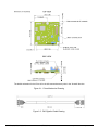
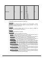
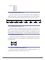
The default orientation for the Prime is for the silk-screened arrow to point in the “forward” direction.
Figure 3-1: Prime Mechanical Drawing
Figure 3-2: PNI Pigtailed Cable Drawing
深圳市铭之光电子技术有限公司 全国服务热线 : 400-883-3391
http://www.sensorexpert.com.cn
4 Set-Up
This section describes how to configure, program, and control the Prime in your host
system. To install the Prime into your system, follow these steps:
•
•
•
•
•
Make electrical connections to the Prime
Evaluate the Prime using the included StudioPrime Program
Choose a mounting location
Mechanically mount the Prime
Perform user calibration
Before you install the module, it can be evaluated with the StudioPrime outside of your
system. Please see Section 5.
4.1 Electrical Connections
The Prime incorporates both a 16 pin ribbon connector (topside of PCB) and a 9 pin
Molex connector (bottomside of PCB) for connecting the unit to the user’s system. The user
should decide which connector they want to use, and only use this connector. The Prime
will not function properly if commands are sent on both connectors.
The Prime Interface Kit includes the PNI 45 cm (18”) custom pigtailed cable(see Figure
3-2). One end of the cable mates with the Prime’s 9 pin Molex connector while the other
end is not connectorized and has 9 wires accessible. These wires are intended to mate with
the user’s system. The cable’s wires are color coded as indicated in Table 4-1.
The Prime Evaluation Kit includes the same PNI pigtailed cable as provided in the
Interface Kit, plus a 1.8 m (6’) custom dual-connectorized cable. This cable incorporates the
Molex 51146-0900 connector on one end that mates to the Prime and a 9-pin sub-D
connector on the other end to mate with a PC’s serial port. This cable primarily is intended
for basic evaluation of the Prime with a PC,
The pin-out for both connectors is given below in Table 4-1. Pin #1 for both connectors
is indicated in Figure 3-1.
深圳市铭之光电子技术有限公司 全国服务热线 : 400-883-3391
http://www.sensorexpert.com.cn
Table 4-1: Prime Pin Descriptions
Pin #
16 pin Ribbon
Connector
9 pin Molex
Connector
PNI Cable
Wire Color
1
2
3
4
5
6
7
8
9
10
11
12
13
14
15
16
NC
DRDY
GND
~CS
GND
MISO
GND
MOSI
GND
SCLK
GND
RS232 RxD
GND
RS232 TxD
GND
+5 VDC
GND
NC
GND
NC
NC
NC
RS232 TxD
RS232 RxD
+5 VDC
Black
Gray
Green
Orange
Violet
Brown
Yellow
Blue
Red
4.2 Where to Install
The Prime’s wide dynamic range and sophisticated calibration algorithms allow it to
operate in many environments. For optimal performance however, you should mount the
Prime with the following considerations in mind:
4.2.1 Ensure operation in sensors’ linear regime
The Prime can be field calibrated to correct for large static magnetic fields created by
the host system. However, each axis of the Prime has a usable dynamic range of ±100
µT: if the total field exceeds this value for any axis the Prime may not give accurate
heading information. When mounting the Prime, consider the effect of any sources of
magnetic fields in the host environment that, when added to the earth’s field, may take
the sensors out of their linear regime. For example, problems can be caused by large
masses of ferrous metals (such as transformers and vehicle chassis), large electric
currents, permanent magnets, and electric motors.
4.2.2 Locate away from changing magnetic fields
It is not possible to calibrate for changing magnetic anomalies.
For greatest
accuracy, keep the Prime away from sources of local magnetic sources that can change
深圳市铭之光电子技术有限公司 全国服务热线 : 400-883-3391
http://www.sensorexpert.com.cn
with time. Examples of such sources include electrical equipment that will be turned on
and off, or ferrous bodies that will move. Make sure the Prime is not mounted close to
cargo or payload areas that may be loaded with large sources of local magnetic fields.
4.2.3 Mount in a physically stable location
Choose a location that is isolated from excessive shock, oscillation, and vibration.
4.2.4 Preliminary testing
Testing should be performed at an early stage of development to understand and
accommodate the magnetic distortion contributors in a host system. Use the data logger
in StudioPrime, as discussed in Section 5.6, to perform the following tests.
•
Determine the distance range of field distortion. Place the compass in a fixed
position, then move or energize suspect components while observing the output
to determine when they are an influence.
•
Determine if the mounting location’s magnetic field is within the l range of the
compass. With the compass mounted, rotate and tilt the system in as many
positions as possible. While doing so, monitor the magnetometer outputs,
observing if the maximum linear range is exceeded.
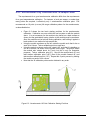
4.3 Mechanical Mounting
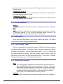
Refer to Figure 3-1 for the Prime’s dimensions, mounting holes, and the orientation of
the reference frame.
The Prime is pre-loaded with calibration coefficients so it nominally indicates north per
the arrow on the PCB, assuming a standard orientation (STD 0°) and minimal local magnetic
distortions. To meet specifications it will be necessary for the user to calibrate the Prime.
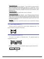
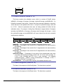
The Prime can be mounted in various orientations. All reference points are based on the
white silk-screened arrow on the top side of the board. Note, however, that StudioPrime
only supports 6 of the mounting configurations, as discussed in Section 5.3.1 and depicted
in Figure 4-1.
深圳市铭之光电子技术有限公司 全国服务热线 : 400-883-3391
http://www.sensorexpert.com.cn
Figure 4-1: Prime Typical Mounting Orientations
深圳市铭之光电子技术有限公司 全国服务热线 : 400-883-3391
http://www.sensorexpert.com.cn
5 Operation with StudioPrime
The StudioPrime evaluation software communicates with the Prime through the COM port
(serial port) of your PC. It puts an easy-to-use, graphical-user interface (GUI) onto the binary
command language used by the Prime. Instead of manually issuing command codes, the user
can use buttons, check boxes, and dialog boxes to control the Prime and obtain data. It reads
the binary responses of the Prime output and formats this into labeled and easy-to-read data
fields. StudioPrime also includes the ability to log and save the outputs of the Prime to a file.
All this allows the user to begin understanding the capabilities of the Prime while using
StudioPrime’s friendly interface. Check PNI’s website (www.pnicorp.com) for the latest version.
5.1 Installation onto a Windows or Mac system
StudioPrime is provided as an executable program which can be downloaded from PNI’s
website.
It will work with Windows 98, Windows ME, Windows 2000, Windows XP,
Windows Vista, and Mac OS X operating systems. Please check the PNI web page at
www.pnicorp.com for the latest version.
Copy StudioPrime to your computer, then launch it by double clicking on the icon.
Follow the installation instructions as prompted.
深圳市铭之光电子技术有限公司 全国服务热线 : 400-883-3391
http://www.sensorexpert.com.cn
5.2 Connection Tab
5.2.1 Initial connection
•
•
•
•
•
Ensure well-charged batteries are installed into the PNI evaluation cable and the
cable is securely attached to the Prime and the PC’s serial port.
Select the serial port the unit is plugged into, which is usually COM 1.
Select 38400 as the baud rate.
Click on the <Connect> button.
Once a connection is made the “Connected” light will turn green and the module
type, firmware version and serial number will be displayed.
5.2.2 Changing baud rate
•
•
•
•
Select the desired baud rate for the module.
Click on the <Power Down> button.
Select same baud rate for the computer.
Click on the <Power Up> button.
5.2.3 Changing modules
Once a connection has been made, StudioPrime will recall the last settings. If a
different module is used, click the <Connect> button once the new module is attached.
This will reestablish a connection assuming the baud rate is unchanged.
深圳市铭之光电子技术有限公司 全国服务热线 : 400-883-3391
http://www.sensorexpert.com.cn
5.3 Configuration Tab
Note: No settings will be changed in the unit until the <SAVE> button has been selected.
5.3.1 Mounting Options
StudioPrime supports 6 mounting orientations, as detailed below. Refer to Figure
4-1 for a drawing illustrating each orientation. (The description in parentheses matches
Figure 4-1, while the initial description matches StudioPrime.) Note that the RS232
interface supports 18 additional (24 total) orientations.
Standard (STD 0°)
When selected the unit is to be mounted with the main board in a horizontal
position (the Z axis magnetic sensor is vertical).
Standard 90 Degrees (STD 90°)
When selected the unit is to be mounted with the main board in a horizontal
position but rotated so the arrow is pointed 90 degrees clockwise from the front of
the host system.
Standard 180 Degrees (STD 180°)
When selected the unit is to be mounted with the main board in a horizontal
position but rotated so the arrow is pointed 180 degrees from the front of the host
system.
Standard 270 Degrees (STD 270°)
When selected the unit is to be mounted with the main board in a horizontal
深圳市铭之光电子技术有限公司 全国服务热线 : 400-883-3391
http://www.sensorexpert.com.cn
position but rotated so the arrow is pointed 270 degrees clockwise from the front of
the host system.
X Sensor Up (“X” Up 0°)
When selected the unit is to be mounted with the main board in a vertical position
(the X axis magnetic sensor is vertical).
Y Sensor Up (“Y” Up 0°)
When selected the unit is to be mounted with the main board in a vertical position
(the Y axis magnetic sensor is vertical).
5.3.2 North Reference
Magnetic
When the “Magnetic” radio button is selected, heading will be relative to Magnetic
North.
True
When the “True” radio button is selected, heading will be relative to True North.
To use North Heading in “True” mode, the declination needs to be set in the
“Declination” window. Refer to Section 6.3 for more information.
5.3.3 Endianess
Use to select either Big Endian or Little Endian; default is Big Endian. See Section
7.2 for more information on appropriate data formats.
5.3.4 Filter Setting (Taps)
The Prime incorporates a finite impulse response (FIR) filter to effectively provide a
more stable heading reading. The number of taps (or samples) represents the amount
of filtering to be performed. The user should select either 0, 4, 8, 16, or 32 taps, with
zero taps representing no filtering. Note that selecting a larger number of taps can
significantly slow the time for the initial sample reading and, if “Flush Filters” is selected,
the rate at which data is output. The default setting is 8 taps.
5.3.5 Acquisition Settings
Mode
• “Poll” mode should be selected when the host system will poll the Prime for
data. StudioPRIME allows the user to simulate this on their PC. In this case,
StudioPRIME requests data from the Prime module at a relatively fixed basis.
• “Push” mode should be selected if the user will have the Prime output data at
a relatively fixed rate to the host system. In this case the Prime module is
pushing data out to StudioPRIME at a relatively fixed rate.
Poll Delay
The Poll Delay is relevant when Poll Mode is selected, and is the time delay, in
深圳市铭之光电子技术有限公司 全国服务热线 : 400-883-3391
http://www.sensorexpert.com.cn
seconds, between the completion of StudioPRIME receiving one set of sampled data
and requesting the next sample set. If the time is set to 0 then StudioPRIME
requests new data as soon as the previous request has been fulfilled. Note that the
inverse of the Poll Delay is somewhat greater than the sample rate, since the Poll
Delay does not include actual acquisition time.
Interval Delay
The Interval Delay is relevant when Push Mode is selected, and is the time delay,
in seconds, between completion of the Prime module sending one set of sampled
data and the start of sending the next sample set. If the time is set to 0 then the
Prime will begin sending new data as soon as the previous data set has been sent.
Note that the inverse of the Interval Delay is somewhat greater than the sample rate,
since the Interval Delay does not include actual acquisition time.
Acquire Delay
The Acquire Delay sets the time between samples taken by the module, in
seconds. This is an internal setting that is NOT tied to the time with which the
module transmits data to StudioPRIME or the host system. Generally speaking, the
Acquire Delay is either set to 0, in which case the Prime is constantly sampling or set
to equal either the Poll Delay or Interval Delay values. The advantage of running
with an Acquire Delay of 0 is that the FIR filter can run with a relatively high Tap
value to provide stable and timely data. The advantage of using a greater Acquire
Delay is that power consumption can be reduced, assuming the Interval or Poll Delay
are no less than the Acquire Delay.
Flush Filters
The filtering is set to only update the filter with the last sample taken, for example
once the initial 8 samples are taken (assuming Taps is set to the default value of 8)
any new sample is added to the end with the first sample being dropped. In the case
where the “Acquire Time” is set to a value it would be prudent to set the unit to flush
the filter prior to calculating the heading. This flushing will require the unit to take 8
new samples to use for the calculation.
Note: If “Flush Filters” is checked, it will take longer for the unit to output updated data.
5.3.6 Calibration Settings
The Prime supports both magnetometer and accelerometer calibration. These
calibrations can be performed independently or simultaneously.
StudioPrime inputs for these calibrations are discussed below.
The relevant
See Section 6.2 for
information on how to perform a calibration.
Stability Checking
By default the unit will wait for the readings to be stable for 3 consecutive
readings when in calibration mode prior to saving the sample for use in the
calibration. This is why the unit must be held steady between points during the User
Calibration. This stability helps to ensure a proper heading and allow for higher
accuracy, but it also takes more time. If the user de-selects the check box, then the
unit will NOT wait for a stable reading and instead take a reading once the minimum
change between points threshold has been met.
深圳市铭之光电子技术有限公司 全国服务热线 : 400-883-3391
http://www.sensorexpert.com.cn
Automatic Sampling
When selected, the unit will take a point once the minimum change requirement
and the stability check requirement (if selected) have been satisfied. If the user
wants more control over when a point will be taken, then Automatic Sampling should
be deselected. Once deselected, the <Take Sample> button on the Calibration tab
will be active. Clicking on the <Take Sample> button will indicate to the unit to take a
sample once the minimum requirements are met.
Calibration Points
The user can select the number of points to take during a calibration. A minimum
of 12 sample points are needed for a successful magnetometer calibration, while 18
samples are recommended for either accelerometer-only calibration or simultaneous
magnetometer and accelerometer calibration.
Mag Only Calibration
Select this when only magnetometer calibration will be performed.
Accel Only Calibration
Select this when only an accelerometer calibration will be performed.
Accel and Mag Calibration
Select this when magnetometer and accelerometer calibrations will be performed
simultaneously.
Enable 3D Model
This box is located in the lower left corner of the window, and checking the box
enables StudioPrime’s live-action 3-D rendering of a helicopter, shown on the Test
tab. The default is for the 3D model to be enabled (box checked), but some
computer systems may not have the graphics capability to render this model, and it
may be necessary to turn off this feature.
5.3.7 Default
Clicking this button reverts the StudioPrime program to the factory default settings.
5.3.8 Revert
This button will have the StudioPrime program read the settings from the unit and
display them on the screen.
深圳市铭之光电子技术有限公司 全国服务热线 : 400-883-3391
http://www.sensorexpert.com.cn
5.4 Calibration Tab
5.4.1 Samples
Clicking on the <Start> button begins the calibration process.
To take a sample point, the unit will need to be held steady for a short time.
Assuming Automatic Sampling is selected (set on the Configuration tab), the window will
indicate when the sample has been taken by incrementing the sample number. At this
point, the module’s orientation should be changed and held steady for the next sample.
Once the pre-set number of samples has been taken (set on the Configuration tab) the
calibration is complete. Refer to Section 6 for the recommended calibration points for
each calibration method.
5.4.2 Calibration Results
Once calibration is complete the “Calibration Results” window will indicate the quality
of the calibration. This applies to both magnetometer and accelerometer calibration.
The X, Y, and Z “Dist Coverage” values show a percentage of each vector that has been
covered during the calibration. The only way to get a Z value greater than 50% would be
to take some points with the unit upside-down. The “Field Std Dev” values for Mag
深圳市铭之光电子技术有限公司 全国服务热线 : 400-883-3391
http://www.sensorexpert.com.cn
Score and Accel Score indicate the overall quality of the calibration. The “Field Std Dev”
Mag Score should be <0.1 and the Accel Score value should be <2. If a better score is
needed, click on the <Start> button to begin a new calibration. See Section 6.2 for
additional information.
If a Mag Only Calibration is performed, the Mag Score will reflect the new
magnetometer calibration, while the Accel Score will be grayed out and represent the
last saved Accel Score values. Similarly, if an Accel Only Calibration is performed the
Accel Score will reflect the new accelerometer calibration and the Mag Score will be
grayed out and reflect the last saved Mag Score values.
If the <Stop> button is clicked during a calibration process prior to taking 12 samples,
this will abort the calibration. (The <Start> button turns into the <Stop> button once the
calibration process is started.) The scores associated with the calibration method that
was aborted will be -1, while scores unassociated with the aborted calibration method
will be grayed out and represent their last saved values.
If the calibration is acceptable, then click the <Save Current User Cal> button to save
the calibration. If this button is not selected then the unit will need to be recalibrated
after a power cycle.
Note: The values in μT or mg refer to the quality of the calibration and NOT the accuracy of the
heading. It is possible to have a good calibration but poor accuracy if the magnetic field the unit
is exposed to during calibration changes after calibration.
5.4.3 Current Configuration
These indicators mimic the pertinent selections made on the Configuration tab.
5.4.4 Options
Audible Feedback:
If selected, StudioPrime gives an audible signal when a calibration point is taken.
Note that an audible signal also will occur when the <Start> button is clicked, but no
data will be taken.
5.4.5 Clear
Clear Mag Cal to Factory:
This button clears the user’s calibration of the magnetometers. Once selected,
the unit reverts to its factory magnetometer calibration. To save the “Clear” in nonvolatile memory, click the <Save Cfg > button.
深圳市铭之光电子技术有限公司 全国服务热线 : 400-883-3391
http://www.sensorexpert.com.cn
Clear Accel Cal to Factory:
This button clears the user’s calibration of the accelerometers. Once selected,
the unit reverts back to its factory accelerometer calibration. To save the “Clear” in
non-volatile memory, click the <Save Cfg> button.
Save Cfg:
This button is only used in conjunction with either of the two buttons detailed
above.
5.5 Test Tab
5.5.1 Current Reading
Once the <GO> button is selected the unit will begin outputting Heading, Pitch and
Roll information. Selecting the <Stop> button or changing tabs will halt the output of the
unit.
Contrast
Selecting this box sets the “Current Readings” window to have yellow lettering on
a black background, rather than black lettering on a white background.
5.5.2 Acquisition Settings
These indicators mimic the pertinent selections made on the Configuration tab.
深圳市铭之光电子技术有限公司 全国服务热线 : 400-883-3391
http://www.sensorexpert.com.cn
5.5.3 3D Model
The helicopter will follow the movement of the attached module and give a visual
representation of the module’s orientation, assuming the “Enable 3D Model Display” box
is selected on the Configuration tab.
5.6 Data Logger Tab
StudioPrime can capture measurement data and then export it to a text file. To acquire
data and export it, follow the procedure below:
•
•
•
•
•
Select the data to log in the “Data” window.
Use Shift-Ctrl-Click and Ctrl-Click to select multiple items.
Click on the <GO> button to start logging; click the <STOP> button to stop
logging.
Click on the <Export> button to save the data to a file.
Click on the <Clear> button to clear the data from the window.
Note: The data logger use ticks for time reference. A tick is 1/60 second.
深圳市铭之光电子技术有限公司 全国服务热线 : 400-883-3391
http://www.sensorexpert.com.cn
5.7 System Log Tab
The System Log tab shows all communication between StudioPrime and the Prime
module since StudioPrime was opened. Closing StudioPrime will erase the system log.
Select the <Export> button, at the bottom right of the screen, to save the system log to a
text file.
深圳市铭之光电子技术有限公司 全国服务热线 : 400-883-3391
http://www.sensorexpert.com.cn
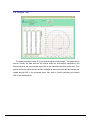
5.8 Graph Tab
The graph provides a 2-axis (X,Y) plot of the measured field strength. The graph can be
used to visually see hard and soft iron effects within the environment measured by the
Prime module as well as corrected output after a user calibration has been performed. (The
screen shot shown shows the MX and MY readings as the module was held horizontally and
rotated through 360º in the horizontal plane, then held in vertical orientation and rotated
360º in the vertical plane.)
深圳市铭之光电子技术有限公司 全国服务热线 : 400-883-3391
http://www.sensorexpert.com.cn
6 User Calibration
Sources of magnetic distortion that are positioned near the Prime in the user’s system will
distort the Earth’s local magnetic field and need to be compensated for before implementing the
Prime in the host system. Examples of such sources include ferrous metals and alloys (ex. iron,
nickel, non-stainless steel, etc.), batteries, permanent magnets, wires, and electric motors. This
compensation is accomplished by calibrating the Prime’s magnetometers while mounted in the
user’s system. In the user’s system it is expected the sources of magnetic distortion will remain
fixed relative to the Prime’s position. By performing a user calibration procedure, the Prime
identifies these local sources of magnetic distortion and subtracts these magnetic effects from
the overall reading to provide an accurate compass heading.
Additionally, the Prime’s MEMS accelerometers gradually may change over time and it may
be desirable to recalibrate the accelerometers from time-to-time. The accelerometer calibration
procedure corrects for changes in accelerometer gain, offset, and cross axis terms. Unlike the
magnetometers, the accelerometers may be calibrated outside the host system. Accelerometer
calibration is more sensitive to noise or hand jitter than magnetometer calibration, especially for
subsequent use at high tilt angles. Because of this, a stabilized fixture is recommended for
accelerometer calibration, although resting the unit against a stable surface often is sufficient.
Alternatively, the Prime can be returned to PNI for recalibration.
Since change in the
accelerometers is gradual and relatively small, accelerometer calibration is optional.
Key Points
1. Magnetic calibration requires incorporating the module in the user’s system such that the
magnetic components of the user’s system can be compensated for.
Full sphere
coverage during calibration is ideal, but not necessary to obtain a good calibration.
2. Even though heading is only specified to a tilt angle of ≤45°, calibrating at >45° generally
will improve accuracy when operating near the specification limit of 45°.
3. Accelerometer calibration requires that the module essentially be rotated through a full
sphere of coverage. However, it does not require that the module be incorporated into
the user’s system to perform the calibration.
4. Magnetic and accelerometer calibration can be performed simultaneously. However, it
may be easier to perform them separately since the requirements of each calibration are
significantly different. (Magnetic calibration requires the module be incorporated in the
深圳市铭之光电子技术有限公司 全国服务热线 : 400-883-3391
http://www.sensorexpert.com.cn
user’s system, while accelerometer calibration requires full sphere coverage.)
5. Pay attention to the calibration scores. See Section 7.3.18 for the score meanings.
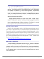
6.1 Magnetic Field Calibration Theory
The primary object of a magnetometer calibration is to compensate for distortions to the
magnetic field caused by the host system. To that end, the Prime needs to be mounted
within the host system and the entire application needs to be moved as a single unit during
the calibration. Movement should include at least 180˚ of horizontal rotation (yaw), but to
achieve the best accuracy a full 360˚ of horizontal rotation with as many different tilt angles
as possible during the rotation is recommended.
6.1.1 Hard and Soft Iron Effects
Hard iron distortions are caused by permanent magnets and magnetized steel or iron
objects within close proximity to the sensors. This type of distortion will remain constant
and in a fixed location relative to the sensors for all heading orientations. Hard-iron
distortions add a constant magnitude field component along each axis of sensor output
and are compensated for by using a saturation method.
Soft-iron distortions are the result of interactions between the Earth’s magnetic field
and any magnetically “soft” material within close proximity to the sensors. In technical
terms, soft materials have a high permeability. The permeability of a given material is a
measure of how well it serves as a path for magnetic lines of force, relative to air, which
has an assigned permeability of one.
The Prime 3-axis digital compass features soft-iron and hard-iron correction.
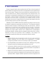
6.1.2 Pitch and Roll
The Prime uses accelerometers to measure the orientation of the compass with
respect to gravity. Since the compass also measures the complete magnetic field, the
Prime can correct for the tilt of the compass to provide an accurate heading.
The Prime utilizes Euler angles as the method for determining accurate orientation.
This method is the same used in aircraft orientation where the outputs are Heading
(Yaw), Pitch and Roll. When using Euler angles, roll is defined as the angle rotated
around an axis through the center of the fuselage while pitch is rotation around an axis
深圳市铭之光电子技术有限公司 全国服务热线 : 400-883-3391
http://www.sensorexpert.com.cn
through the center of the wings. These two rotations are independent of each other
since the rotation axes rotate with the plane body.
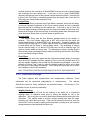
For the Prime a positive pitch is when the front edge of the board is rotated upward
and a positive roll is when the right edge of the board is rotated downward.
Figure 6-1: Positive & Negative Roll and Pitch Definition
6.2 Calibration Procedures
Below are instructions for performing both magnetometer and accelerometer user
calibrations of the Prime module using StudioPrime and the PNI cable. All StudioPrime
application functions are available through the Prime’s RS232 interface, allowing this
procedure to be translated into a user’s imbedded solution. These calibration sequences
demonstrate a good distribution of the recommended minimum sample points: additional
sample points may be taken.
Once calibration is complete the “Calibration Results” window will indicate the quality of
the calibration. This applies to both magnetometer and accelerometer calibration. The X, Y,
and Z values show a percentage of each vector that has been covered during the
calibration. For magnetometer calibration, a score of >85% is desirable for the X and Y
vectors. The only way to get a Z value greater than 50% would be to take some points with
the unit upside-down. For accelerometer calibration, a score of >95% is desirable for the X,
Y vectors, and >90% for Z vectors. The values shown in μT for Mag Score and mg for
Accel Score refer to the standard deviation of the measured samples when compared to the
calculated values. The value for the Mag Score should be <0.1 and the value for the Accel
Score should be <2.
With the Prime module connected and communicating with StudioPrime, go to the
深圳市铭之光电子技术有限公司 全国服务热线 : 400-883-3391
http://www.sensorexpert.com.cn
Configuration tab and configure StudioPrime as follows:
•
•
•
•
•
•
In the Filter Settings window set Taps to 32. (32 taps is recommended. Fewer
taps should work, but may not give as accurate a calibration.)
Calibration Settings: Check the Stability Checking box
Check the Automatic Sampling box
Set Calibration Points to at least 12 if only the magnetometers will be calibrated,
and at least 18 if the accelerometers or the accelerometers & magnetometers will
be calibrated. More sample points can be selected if the user desires.
Select “Mag Only Calibration”, “Accel Only Calibration”, or “Accel and Mag
Calibration”, depending on which calibration procedure will be undertaken.
Click on the <Save> button.
Go to the Calibration tab. To perform a calibration, refer to the recommended calibration
pattern given in the sections below, and then adhere to the following procedure:
•
•
•
•
•
Hold the module level and stable.
Click on the <Start> button and wait for a sample to be taken.
Rotate the module to the next pattern position and hold the module stable until
the next sample is taken.
Repeat this until all samples, as set above, are taken.
Click on the <Save Current User Cal> button
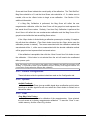
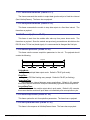
6.2.1 Magnetometer Only Calibration with 12 Sample Points
The following procedure is recommended for magnetic calibration.
Additional
sample points with the module flipped upside down are also desirable if possible.
Move the module to the following positions, noting that these are not absolute
heading directs, but rather relative headings referenced to your initial heading sample.
(i.e. yaw is relative to the starting orientation, and does not need to be North.)
Note: Once you begin taking calibration points, pausing between desired calibration points will
cause unintentional points to be taken with auto sampling enabled.
Module approximately level
• 0° yaw
• 90° yaw
• 180° yaw
• 270° yaw
With module pitched positively ≥ 10 deg (recommended +50 degrees)
• 30° yaw with small negative roll
• 120° yaw with small positive roll
• 210° yaw with small negative roll
• 300° yaw with small positive roll
深圳市铭之光电子技术有限公司 全国服务热线 : 400-883-3391
http://www.sensorexpert.com.cn
With the module pitched negatively ≥ -10 deg (recommended -50 degrees)
• 60° yaw with small positive roll
• 150° yaw with small negative roll
• 240° yaw with small positive roll
• 330° yaw with small negative roll
Figure 6-2: Magnetometer 12 Point Calibration Pattern
深圳市铭之光电子技术有限公司 全国服务热线 : 400-883-3391
http://www.sensorexpert.com.cn
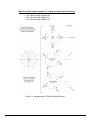
6.2.2 Accelerometer Only Calibration with 18 Sample Points
The requirements for a good accelerometer calibration differ from the requirements
for a good magnetometer calibration. For instance, a level yaw sweep, no matter how
many points are acquired, is effectively only 1 accelerometer calibration point.
PNI
recommends an 18 point (or more) full range calibration pattern for the accelerometer,
as described below.
•
•
•
•
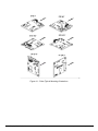
Figure 6-3 shows the two basic starting positions for the accelerometer
calibration. Calibration can occur within the user’s system or with the module
alone. It is not necessary for the module to be placed on a hard surface as
shown, but the gravitational vector (relative to the module) must be as shown.
Also, the module must be held still during calibration, and holding it against a
hard surface is one method to help ensure this.
Using the module as shown on the left, rotate the module such that it sits on
each of its 6 faces. Take a calibration point on each face.
Using the module as shown on the left, rotate it 45° such that it is standing on
one of its corners, as shown for the module on the right. The picture shows
the module also rotated about its Z axis, but this is only for illustration
purposes. Take a calibration point (0°). Now tilt the module back 45° and
take another calibration point (+45°), then tilt the module forward 45° and
take another calibration point (-45°). Repeat this 3-point process by holding
the module on each of its 4 corners.
Note that the 18 calibration points can be obtained in any order.
Figure 6-3: Accelerometer 18 Point Calibration Starting Positions
深圳市铭之光电子技术有限公司 全国服务热线 : 400-883-3391
http://www.sensorexpert.com.cn
6.2.3 Accel and Mag Calibration
The Prime allows for a simultaneous magnetometer and accelerometer user
calibration. This requires a good (full range) calibration pattern, stable measurements
(not handheld), and installation in the user’s system such that the appropriate local
magnetic environment is present. The accelerometer calibration pattern discussed in
Section 6.2.2 will work for a simultaneous calibration. Optimal performance is obtained
when all rotations of the cube are performed towards magnetic north to achieve the
widest possible magnetic field distribution.
Note that combining calibrations only makes sense if all the integrated system’s
magnetic distortions (steel structures or batteries, for instance) are present and fixed
relative to the Prime when calibrating. If Accelerometer Only calibration is performed,
the user’s system distortions are not relevant, which allows for the Prime to be removed
from the system in order to perform the Accelerometer Only calibration.
6.3 Declination Value
Declination, also called magnetic variation, is the difference between true and magnetic
north, relative to a point on the earth. It is measured in degrees east or west of true north.
Correcting for declination is accomplished by storing the correct declination angle, and then
changing the heading reference from magnetic north to true north. Declination angles vary
throughout the world, and change very slowly over time. For the greatest possible accuracy,
go to the National Geophysical Data Center web page below to get the declination angle
based on your latitude and longitude:
http://www.ngdc.noaa.gov/geomagmodels/Declination.jsp
6.4 Other Limitations
The Prime measures the total magnetic field within its vicinity, and this is a combination
of the earth’s magnetic field and local magnetic sources. The Prime can compensate for
local static magnetic sources that do not exceed the dynamic range of its magnetometers.
A magnetic source which is not static can create errors, and it is not possible to compensate
for such a dynamic nature. In such cases, moving the Prime away from dynamic magnetic
fields is recommended.
深圳市铭之光电子技术有限公司 全国服务热线 : 400-883-3391
http://www.sensorexpert.com.cn
7 Operation with RS232 Interface
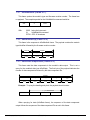
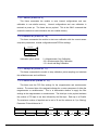
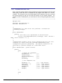
7.1 Datagram Structure
Transport layer for RS-232 communication:
ByteCount
(UInt16)
Packet Frame
(1 - 4092 UInt8)
Frame
ID
(UInt8)
CRC-16
(UInt16)
Payload
(1 - 4091 UInt8)
Figure 7-1: Datagram Structure
The ByteCount is the total number of bytes in the packet including the CRC-16. CRC-16
is calculated starting from the ByteCount to the last byte of the Packet Frame (see included
C function at end of document). The ByteCount and CRC-16 are always transmitted in BIG
ENDIAN.
7.2 Parameter Formats
Floating Point
The floating-point based parameters are in the IEEE standard format, ANSI/IEEE
Std 754-1985.
64-Bit (double precision floating point)
Shown below is the 64-bit float format in big Endian, in little Endian bytes are in
reverse order in 4 byte groups (i.e.: big Endian: ABCDEFGH little Endian: DCBA
HGFE).
63 62
S
5251
Exponent
0
Mantissa
The value (v) is determined as (if and only if 0 < Exponent < 2047): v = (-1)S *
2(Exponent-1023) * 1.Mantissa
32-Bit (single precision floating point)
Shown below is the 32-bit float format in big Endian, in little Endian all 4 bytes
are in reverse order (LSB first).
深圳市铭之光电子技术有限公司 全国服务热线 : 400-883-3391
http://www.sensorexpert.com.cn
3130
S
2322
0
Exponent
Mantissa
The value (v) is determined as (if and only if 0 < Exponent < 255): v = (-1)S *
2(Exponent-127) * 1.Mantissa
Note: Please refer to ANSI/IEEE Std 754-1985 for more information. It is also recommended
that you refer to the compiler you are using on how it implements floating-point formats.
Signed 32-bit Integer (SInt32)
SInt32 based parameters are signed 32 bit numbers (2’s compliment). Bit 31
represents the sign of the value (0=positive, 1=negative)
31
24 23
16 15
8 7
msb
0
lsb
Big Endian
7
0 15
8 23
16 31
lsb
24
msb
Little Endian
Signed 16-bit Integer (SInt16)
SInt16 based parameters are signed 16 bit numbers (2’s compliment). Bit 15
represents the sign of the value (0=positive, 1=negative)
15
8 7
msb
0
lsb
Big Endian
7
0 15
lsb
8
msb
Little Endian
Signed 8-bit Integer (SInt8)
UInt8 based parameters are unsigned 8-bit numbers. Bit 7 represents the sign of
the value (0=positive, 1=negative)
7
0
byte
深圳市铭之光电子技术有限公司 全国服务热线 : 400-883-3391
http://www.sensorexpert.com.cn
Unsigned 32-bit Integer (UInt32)
UInt32 based parameters are unsigned 32 bit numbers.
31
24 23
8 7
16 15
msb
0
lsb
Big Endian
0 15
7
8 23
16 31
lsb
24
msb
Little Endian
Unsigned 16-bit Integer (UInt16)
UInt16 based parameters are unsigned 16 bit numbers.
15
8 7
msb
0
lsb
Big Endian
7
0 15
lsb
8
msb
Little Endian
Unsigned 8-bit Integer (UInt8)
UInt8 based parameters are unsigned 8-bit numbers.
7
0
byte
Boolean
Boolean is a 1-byte parameter that MUST have the value 0 (false) or 1 (true).
7
0
byte
深圳市铭之光电子技术有限公司 全国服务热线 : 400-883-3391
http://www.sensorexpert.com.cn
7.3 Commands & Communication Frames
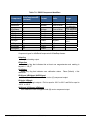
The Prime’s RS232 interface command set is given below in , and descriptions of each
command follow in the subsequent sections.
Table 7-1: RS232 Command Set
Frame
Command
ID
1
2
3
4
5
6
7
8
9
10
11
kGetModInfo
kModInfoResp
kSetDataComponents
kGetData
kDataResp
kSetConfig
kGetConfig
kConfigResp
kSave
kStartCal
kStopCal
12
kSetParam
13
kGetParam
14
kParamResp
15
16
17
18
19
20
21
22
23
24
25
26
27
28
29
30
31
36
37
kPowerDown
kSaveDone
kUserCalSampCount
kUserCalScore
kSetConfigDone
kSetParamDone
kStartIntervalMode
kStopIntervalMode
kPowerUp
kSetAcqParams
kGetAcqParams
kAcqParamsDone
kAcqParamsResp
kPowerDownDone
kFactoryUserCal
kFactorUserCalDone
kTakeUserCalSample
kFactoryInclCal
kFactoryInclCalDone
深圳市铭之光电子技术有限公司 Description
Queries the modules type and firmware revision number.
Response to kGetModInfo
Sets the data components to be output.
Queries the module for data
Response to kGetData
Sets internal configurations in the module
Queries the module for the current internal configuration value
Response to kGetConfig
Commands the module to save internal and user calibration
Commands the module to start user calibration
Commands the module to stop user calibration
Sets the FIR filter settings for the magnetometer &
accelerometer sensors.
Queries for the FIR filter settings for the magnetometer &
accelerometer sensors.
Contains the FIR filter settings for the magnetometer &
accelerometer sensors.
Used to completely power-down the module
Response to kSave
Sent from the module after taking a calibration sample point
Contains the calibration score
Response to kSetConfig
Response to kSetParam
Commands the module to output data at a fixed interval
Commands the module to stop data output at a fixed interval
Sent after wake up from power down mode
Sets the sensor acquisition parameters
Queries for the sensor acquisition parameters
Response to kSetAcqParams
Response to kGetAcqParams
Response to kPowerDown
Clears user magnetometer calibration coefficients
Response to kFactoryUserCal
Commands the unit to take a sample during user calibration
Clears user accelerometer calibration coefficients
Response to kFactoryInclCal
全国服务热线 : 400-883-3391
http://www.sensorexpert.com.cn
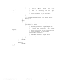
7.3.1 kGetModInfo (frame ID 1)
This frame queries the module's type and firmware revision number. The frame has
no payload. The complete packet for the kGetModInfo command would be:
0005
01
With:
EFD4
0005 being the byte count
01
kGetModInfo command
EFD4 CRC-16 checksum
7.3.2 kModInfoResp (frame ID 2)
This frame is the response to kGetModInfo frame. The payload contains the module
type identifier followed by the firmware revision number.
Frame ID
Payload
2
Type
Revision
kUlnt8
UInt32
UInt32
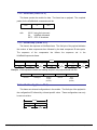
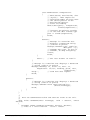
7.3.3 kSetDataComponents (frame ID 3)
This frame sets the data components in the module's data output. This is not a
query for the module's data (see kGetData). The first byte of the payload indicates the
number of data components followed by the data component IDs.
Payload
Count
ID1
ID2
ID3
IDCount
UInt8
UInt8
UInt8
UInt8
UInt8
Example: To query the heading and pitch, the payload should contain:
Payload
3
2
5
24
Frame ID
ID Count
Heading ID
Pitch ID
When querying for data (kGetData frame), the sequence of the data component
output follows the sequence of the data component IDs as set in this frame.
深圳市铭之光电子技术有限公司 全国服务热线 : 400-883-3391
http://www.sensorexpert.com.cn
Table 7-2: RS232 Component Identifiers
Component
DataComponentID
(decimal)
Format
Units
Range
kHeading
5
Float32
degrees
kDistortion
8
Boolean
True or False
kCalStatus
9
Boolean
True or False
kPAligned
kRAligned
kIZAligned
kPAngle
21
22
23
24
Float32
Float32
Float32
Float32
G
G
G
degrees
kRAngle
25
Float32
degrees
0.0˚ to 359.9˚
False (Default)
= no distortion
False (Default)
= not calibrated
-1.0 to 1.0
-1.0 to 1.0
-1.0 to 1.0
-90.0˚ to 90.0˚
-180.0˚
to
180.0˚
KXAligned
KYAligned
KZAligned
27
28
29
Float32
Float32
Float32
μT
μT
μT
Component types for kSetDataComponents & kDataResp frames:
kHeading
Compass heading output.
kDistortion
Read only flag that indicates that at least one magnetometer axis reading is
beyond +/- 100 µT.
kCalStatus
Read only flag that indicates user calibration status.
calibrated.
False (Default) = Not
kPAligned, kRAligned & kIZAligned
User calibrated Earth’s acceleration vector (G) component output.
kPAngle, kRAngle
Pitch and Roll angle outputs. Pitch is equal to -90.0˚ to 90.0˚ and Roll is equal to
-180.0˚ to 180.0˚.
kXAligned, kYAligned, kZAligned
User calibration Earth’s magnetic field (M) vector component output.
深圳市铭之光电子技术有限公司 全国服务热线 : 400-883-3391
http://www.sensorexpert.com.cn
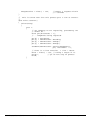
7.3.4 kGetData (frame ID 4)
This frame queries the module for data. The frame has no payload. The complete
packet for the kGetModInfo command would be:
00 05
04
with
BF71
00 05 being the byte count
04
kGetData command
BF71 CRC-16 checksum
7.3.5 kDataResp (frame ID 5)
The frame is the response to kGetData frame. The first byte of the payload indicates
the number of data components then followed by the data component ID-value pairs.
The
sequence
of
the
components
Ids
follows
the
sequence
set
in
the
kSetDataComponents frame.
Payload
Count
ID1
ValueID1
ID2
ValueID2
IDCount
ValueIDCount
UInt8
UInt8
ID
Specific
UInt8
ID
Specific
UInt8
ID
Specific
Example: If the response contains the heading and pitch, the payload would look like:
2
5
359.9
24
10.5
ID Count
Heading ID
Heading
Output
(Float32)
Pitch ID
Pitch
Output
(Float32)
7.3.6 kSetConfig (frame ID 6)
This frame sets internal configurations in the module. The first byte of the payload is
the configuration ID followed by a format specific value. These configurations can only
be set one at time.
Payload
Config ID
Value
UInt8
ID
Specific
深圳市铭之光电子技术有限公司 全国服务热线 : 400-883-3391
http://www.sensorexpert.com.cn
Example: To configure the declination, the payload would look like:
1
10.0
Declination ID
Declination
Angle
(Float32)
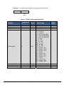
Table 7-3: RS232 Configuration Identifiers
Settings
Configuration
Format
ID
kDeclination
kTrueNorth
kBigEndian
1
2
6
Float32
Boolean
Boolean
kMountingRef
10
UInt8
kUserCalStableCheck
11
kUserCalNumPoints
12
kUserCalAutoSampling 13
深圳市铭之光电子技术有限公司 Boolean
UInt32
Boolean
Default
Values
Units/ Range
-180˚ to 180˚
True or False
True or False
1 = Standard
2 = X axis up
3 = Y axis up
4 = -90° heading offset
5 = -180° heading offset
6 = -270° heading offset
7 = Z down
8 = X + 90°
9 = X + 180°
10 = X + 270°
11 = Y + 90°
12 = Y + 180°
13 = Y + 270°
14 = Z down + 90°
15 = Z down + 180°
16 = Z down + 270°
17 = X down
18 = X down +90
19 = X down +180
20 = X down +270
21 = Y down
22 = Y down +90
23 = Y down +180
24 = Y down + 270
0˚
False
True
True or False
12 – 50
True or False
True
12
True
全国服务热线 : 400-883-3391
1
http://www.sensorexpert.com.cn
kBaudRate
14
UInt8
0 – 300
1 – 600
2 – 1200
3 – 1800
4 – 2400
5 – 3600
6 – 4800
7 – 7200
8 – 9600
9 – 14400
10 – 19200
11 – 28800
12 – 38400
13 – 57600
14 - 115200
12
Configuration parameters and settings for kSetConfig:
kDeclination
This sets the declination angle to determine True North heading. Positive
declination is easterly declination and negative is westerly declination. This is not
applied until kTrueNorth is set to true.
kTrueNorth
Flag to set compass heading output to true north heading by adding the
declination angle to the magnetic north heading.
kBigEndian
Flag to set the Endianness of packets
kMountingRef
This sets the reference orientation for the module:
Standard: When selected the unit is to be mounted with the main board in a
horizontal position (the Z axis magnetic sensor is vertical).
X Sensor Up: When selected the unit is to be mounted with the main board in a
vertical position: the X axis magnetic sensor is vertical and points up.
Y Sensor Up: When selected the unit is to be mounted with the main board in a
vertical position: the Y axis magnetic sensor is vertical and points up.
X Sensor Down: When selected the unit is to be mounted with the main board
in a vertical position: the X axis magnetic sensor is vertical and points down.
Y Sensor Down: When selected the unit is to be mounted with the main board
in a vertical position: the Y axis magnetic sensor is vertical and points down.
Standard 90 Degrees: When selected the unit is to be mounted with the main
board in a horizontal position but rotated so the arrow is pointed 90 degrees
counterclockwise to the front of the host system.
Standard 180 Degrees: When selected the unit is to be mounted with the main
board in a horizontal position but rotated so the arrow is pointed 180 degrees
counterclockwise to the front of the host system.
Standard 270 Degrees: When selected the unit is to be mounted with the main
board in a horizontal position but rotated so the arrow is pointed 270 degrees
counterclockwise to the front of the host system.
深圳市铭之光电子技术有限公司 全国服务热线 : 400-883-3391
http://www.sensorexpert.com.cn
kUserCalStableCheck
This flag is used during user calibration. If set to FALSE, the module will take a
point if the magnetic field has changed more than 23 µT in either axis. If set to
TRUE the unit will take a point if the magnetic field has a stability of 30µT in each
direction and the previous point changed more than 5µT and acceleration vector
delta within 2 mg.
kUserCalNumPoints
The maximum number samples taken during user calibration.
kUserCalAutoSampling
This flag is used during user calibration. If set to TRUE, the module continuously
takes calibration sample points until the set number of calibration samples. If set to
FALSE, the module waits for kTakeUserCalSample frame to take a sample with the
condition that a magnetic field vector component delta is greater than 5 micro Tesla
from the last sample point.
kBaudRate
Baud rate index value. A power-down power-up cycle is required when changing
the baud rate.
7.3.7 kGetConfig (frame ID 7)
This frame queries the module for the current internal configuration value.
The
payload contains the configuration ID requested.
Payload
Config ID
UInt8
7.3.8 kConfigResp (frame ID 8)
This frame is the response to kGetConfig frame.
The payload contains the
configuration ID and value.
Payload
Config ID
Value
UInt8
ID
Specific
Example: If a request to get the set declination angle, the payload would look like:
1
10.0
Declination ID
Declination
Angle
(Float32)
深圳市铭之光电子技术有限公司 全国服务热线 : 400-883-3391
http://www.sensorexpert.com.cn
7.3.9 kSave (frame ID 9)
This frame commands the module to save internal configurations and user
calibration to non-volatile memory.
Internal configurations and user calibration is
restored on power up. The frame has no payload. This is the ONLY command that
causes the module to save information into non-volatile memory.
7.3.10 kStartCal (frame ID 10)
This frame commands the module to start user calibration with the current sensor
acquisition parameters, internal configurations and FIR filter settings.
Payload
Cal O ption
UInt32
Calibration option values:
0 = Magnetometer Only Calibration
100 = Accelerometer Only Calibration
110 = Accel and Mag Calibration
7.3.11 kStopCal (frame ID 11)
This frame commands the module to stop calibration points sampling and calculate
the calibration score and coefficients.
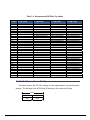
7.3.12 kSetParam (frame ID 12)
This frame sets the FIR filter settings for the magnetometer and accelerometer
sensors. The second byte of the payload indicates the x vector component of either the
magnetometer or accelerometer.
This is to differentiate whether to apply the filter
settings to the magnetometer or accelerometer. The third byte in the payload indicates
the number of FIR taps to use then followed by the filter taps. Each tap is a Float64.
The maximum number of taps that can be set is 32 and the minimum is 0 (no filtering).
Parameter ID should be set to 3.
Payload
Parameter ID
Axis ID
Count
Value1
Value2
Value3
ValueCount
UInt8
UInt8
UInt8
ID
Specific
ID
Specific
ID
Specific
ID
Specific
深圳市铭之光电子技术有限公司 全国服务热线 : 400-883-3391
http://www.sensorexpert.com.cn
Table 7-4: Recommended FIR Filter Tap Values
Count 4 Tap Filter
8 Tap Filter
16 Tap Filter
32 Tap Filter
1
2
3
4
5
6
7
8
9
10
11
12
13
14
15
16
17
18
19
20
21
22
23
24
25
26
27
28
29
30
31
32
01.9875512449729e-2
06.4500864832660e-2
01.6637325898141e-1
02.4925036373620e-1
02.4925036373620e-1
01.6637325898141e-1
06.4500864832660e-2
01.9875512449729e-2
07.9724971069144e-3
01.2710056429342e-2
02.5971390034516e-2
04.6451949792704e-2
07.1024151197772e-2
09.5354386848804e-2
01.1484431942626e-1
01.2567124916369e-1
01.2567124916369e-1
01.1484431942626e-1
09.5354386848804e-2
07.1024151197772e-2
04.6451949792704e-2
02.5971390034516e-2
01.2710056429342e-2
07.9724971069144e-3
01.4823725958818e-3
02.0737124095482e-3
03.2757326624196e-3
05.3097803863757e-3
08.3414139286254e-3
01.2456836057785e-2
01.7646051430536e-2
02.3794805168613e-2
03.0686505921968e-2
03.8014333463472e-2
04.5402682509802e-2
05.2436112653103e-2
05.8693165018301e-2
06.3781858267530e-2
06.7373451424187e-2
06.9231186101853e-2
06.9231186101853e-2
06.7373451424187e-2
06.3781858267530e-2
05.8693165018301e-2
05.2436112653103e-2
04.5402682509802e-2
03.8014333463472e-2
03.0686505921968e-2
02.3794805168613e-2
01.7646051430536e-2
01.2456836057785e-2
08.3414139286254e-3
05.3097803863757e-3
03.2757326624196e-3
02.0737124095482e-3
01.4823725958818e-3
04.6708657655334e-2
04.5329134234467e-1
04.5329134234467e-1
04.6708657655334e-2
7.3.13 kGetParam (frame ID 13)
This frame queries the FIR filter settings for the magnetometer and accelerometer
sensors. The first byte is the kFIRConfig ID followed by the vector axis ID byte.
Payload
Parameter ID
Axis ID
UInt8
UInt8
深圳市铭之光电子技术有限公司 全国服务热线 : 400-883-3391
http://www.sensorexpert.com.cn
Axis IDs: kXAxis = 1
kYAxis = 2
kZAxis = 3
kPAxis = 4
kRAxis = 5
kIZAxis = 6
7.3.14 kParamResp (frame ID 14)
This frame contains the current FIR filter settings for either magnetometer or
accelerometer sensors. The second byte of the payload is the vector axis ID, the third
byte is the number of filter taps then followed by the filter taps. Each tap is a Float64.
Payload
Parameter ID
Axis ID
Count
Value1
Value2
Value3
ValueCount
UInt8
UInt8
UInt8
Filter Top
Value
ID
Specific
ID
Specific
ID
Specific
7.3.15 kPowerDown (frame ID 15)
This frame is used to completely power-down the module.
The frame has no
payload. The unit will power down all peripherals including the RS-232 driver but the
driver chip has the feature to keep the Rx line enabled. Any character sent to the
module causes it to exit power down mode. It is recommended to send the byte oxFFh.
7.3.16 kSaveDone (frame ID 16)
This frame is the response to kSave frame. The payload contains a UInt16 error
code, 0000h indicates no error, 0001h indicates error when attempting to save data into
non-volatile memory.
Payload
Error code
UInt16
7.3.17 kUserCalSampCount (frame ID 17)
This frame is sent from the module after taking a calibration sample point. The
payload contains the sample count with the range of 1 to 32
深圳市铭之光电子技术有限公司 全国服务热线 : 400-883-3391
http://www.sensorexpert.com.cn
Payload
Sample count
UInt32
7.3.18 kUserCalScore (frame ID 18)
This frame contains the calibration score, which is a series of Float32 values:
stdDevErr, xCoverage, yCoverage, zCoverage, xyzAccelCoverage, accelStdDevErr. If a
kStopCal command is sent before 12 points have been acquired (calibration is aborted),
values that were to be updated will be set to -1 except for xyzAccelCoverage, which will
be -101.01. Values for parameters that were not being updated will reflect the last
calibration values. For example, if a Mag Only Calibration is stopped before 12 samples
are taken, the StdDevErr, xCoverage, yCoverage, and zCoverage will all report -1, while
the xyzAccelCoverage and accelStdDevErr will report values from the last successful
accelerometer calibration.
StdDevErr : The compass samples magnetic field standard deviation error.
xCoverage : Percentage of how much of the X magnetometer axis was covered by
the sampling.
yCoverage : Percentage of how much of the Y magnetometer axis was covered by
the sampling.
zCoverage : Percentage of how much of the Z magnetometer axis was covered by
the sampling.
xyzAccelCoverage : Percentage of how much of the accelerometer axes were
covered by the sampling formatted as XXYY.ZZ. XX is the X axis coverage, YY
is the Y axis coverage and ZZ is the Z axis coverage. For example
xyzAccelCoverage = 8590.67 means accelerometer X coverage is 85%, Y
coverage is 90% and Z coverage is 67%.
accelStdDevErr : The accelerometer samples’ field standard deviation error.
7.3.19 kSetConfigDone (frame ID 19)
This frame is the response to kSetConfig frame. The frame has no payload.
7.3.20 kSetParamDone (frame ID 20)
This frame is the response to kSetParam frame. The frame has no payload.
深圳市铭之光电子技术有限公司 全国服务热线 : 400-883-3391
http://www.sensorexpert.com.cn
7.3.21 kStartIntervalMode (frame ID 21)
The frame commands the module to output data (push mode) at a fixed time interval
(See kSetAcqParams). The frame has no payload.
7.3.22 kStopIntervalMode (frame ID 22)
This frame commands the module to stop data output at a fixed time interval. The
frame has no payload.
7.3.23 kPowerUp (frame ID 23)
This frame is sent from the module after wake up from power down mode. The
frame has no payload. Since the module was previously powered down which drives the
RS-232 driver TX line low (break signal), it is recommended to disregard the first byte.
7.3.24 kSetAcqParams (frame ID 24)
This frame sets the sensor acquisition parameters in the unit. The payload should
contain the following:
Payload
PollingMode
FlushFilter
SensorAcqTime
IntervalRespTime
UInt8
UInt8
Float32
Float32
PollingMode:
Flag to set push/poll data output mode. Default is TRUE (poll mode).
FlushFilter:
Flag to set FIR filter flushing every sample. Default is FALSE (no flushing).
SensorAcqTime:
The internal time interval between sensor acquisitions. Default is 0.0 seconds,
this means that the module will reacquire immediately right after the last acquisition.
IntervalRespTime:
The time interval the module output data in push mode. Default is 0.0 seconds,
this means that the module will push data out immediately after an acquisition cycle.
7.3.25 kGetAcqParams (frame ID 25)
This frame queries the unit for acquisition parameters. The frame has no payload.
7.3.26 kAcqParamsDone (frame ID 26)
This frame is the response to kSetAcqParams frame. The frame has no payload.
深圳市铭之光电子技术有限公司 全国服务热线 : 400-883-3391
http://www.sensorexpert.com.cn
7.3.27 kAcqParamsResp (frame ID 27)
This frame is the response to kGetAcqParams frame. The payload should contain
the same payload as the kSetAcqParams frame.
7.3.28 kPowerDownDone (frame ID 28)
This frame is the response to kPowerDown frame.
This indicates that the unit
successfully received the kPowerDone frame and is in the process of powering down.
The frame has no payload.
7.3.29 kFactoryUserCal (frame ID 29)
This frame clears the user magnetometer calibration coefficients. The frame has no
payload. This frame must be followed by the kSave frame to change in non-volatile
memory.
7.3.30 kFactoryUserCalDone (frame ID 30)
This frame is the response to kFactoryUserCal frame. The frame has no payload.
7.3.31 kTakeUserCalSample (frame ID 31)
This frame commands the unit to take a sample during user calibration. The frame
has no payload.
7.3.32 kFactoryInclCal (frame ID 36)
This frame clears the user accelerometer calibration coefficients. The frame has no
payload. This frame must be followed by the kSave frame to change in non-volatile
memory.
7.3.33 kFactoryInclCalDone (frame ID 37)
This frame is the response to kFactoryInclCal frame. The frame has no payload.
深圳市铭之光电子技术有限公司 全国服务热线 : 400-883-3391
http://www.sensorexpert.com.cn
7.4 Code Examples
The following example files (CommProtocol.h, CommProtocol.cp, Prime.h and Prime.cp)
would be used together for proper communication with a Prime module.
NOTE: The user also needs to create the following: SystemSerPort.h; Processes.h, TickGenerator.h.
7.4.1 Header File & CRC-16 Function
// type declarations
typedef struct
{
UInt8 pollingMode, flushFilter;
Float32 sensorAcqTime, intervalRespTime;
} __attribute__ ((packed)) AcqParams;
typedef struct
{
Float32 stdDevErr;
Float32 xCoverage;
Float32 yCoverage;
Float32 zCoverage;
Float32 xyzAccelCoverage;
Float32 accelStdDevErr;
} __attribute__ ((packed)) CalScore;
enum
{
// Frame IDs (Commands)
kGetModInfo = 1,
//
kModInfoResp,
//
kSetDataComponents,
//
kGetData,
//
kDataResp,
//
kSetConfig,
//
kGetConfig,
//
kConfigResp,
//
kSave,
//
kStartCal,
//
kStopCal,
//
kSetParam,
//
kGetParam,
//
kParamResp,
//
kPowerDown,
//
kSaveDone,
//
kUserCalSampCount,
//
kUserCalScore,
//
kSetConfigDone,
//
kSetParamDone,
//
kStartIntervalMode,
//
kStopIntervalMode,
//
kPowerUp,
//
kSetAcqParams,
//
kGetAcqParams,
//
kAcqParamsDone,
//
kAcqParamsResp,
//
kPowerDoneDown,
//
kFactoryUserCal,
//
深圳市铭之光电子技术有限公司 1
2
3
4
5
6
7
8
9
10
11
12
13
14
15
16
17
18
19
20
21
22
23
24
25
26
27
28
29
全国服务热线 : 400-883-3391
http://www.sensorexpert.com.cn
kFactoryUserCalDone,
kTakeUserCalSample,
kFactoryInclCal,
kFactoryInclCalDone,
//
//
//
//
30
31
36
37
// Param IDs
kFIRConfig = 1,//3-AxisID(UInt8)+
//Count(UInt8)+Value(Float64)+...
// Data Component IDs
kHeading = 5,
kDistortion = 8,
kPAligned = 21,
kRAligned,
kIZAligned,
kPAngle,
kRAngle,
kXAligned = 27,
kYAligned,
kZAligned,
//
//
//
//
//
//
//
//
//
//
5 - type Float32
8 - type boolean
21 - type Float32
22 - type Float32
23 - type Float32
24 - type Float32
25 - type Float32
27 - type Float32
28 - type Float32
29 - type Float32
// Configuration Parameter IDs
kDeclination = 1,
// 1 - type Float32
kTrueNorth,
// 2 - type boolean
kMountingRef = 10,
// 10 - type UInt8
kUserCalStableCheck,
// 11 - type boolean
kUserCalNumPoints,
// 12 - type UInt32
kUserCalAutoSampling, // 13 – type boolean
kBaudRate,
// 14 – UInt8
// Mounting Reference IDs
kMountedStandard = 1, // 1
kMountedXUp,
// 2
kMountedYUp,
// 3
kMountedStdPlus90,
// 4
kMountedStdPlus180,
// 5
kMountedStdPlus270,
// 6
// Result IDs
kErrNone = 0,
kErrSave,
// 0
// 1
};
// function to calculate CRC-16
UInt16 CRC(void * data, UInt32 len)
{
UInt8 * dataPtr = (UInt8 *)data;
UInt32 index = 0;
// Update the CRC for transmitted and received data using
// the CCITT 16bit algorithm (X^16 + X^12 + X^5 + 1).
UInt16 crc = 0;
while(len--)
{
crc = (unsigned char)(crc >> 8) | (crc << 8);
crc ^= dataPtr[index++];
crc ^= (unsigned char)(crc & 0xff) >> 4;
crc ^= (crc << 8) << 4;
crc ^= ((crc & 0xff) << 4) << 1;
}
return crc;
}
深圳市铭之光电子技术有限公司 全国服务热线 : 400-883-3391
http://www.sensorexpert.com.cn
7.4.2 CommProtocol.h File
Note: This file contains objects used to handle the serial communication with the unit.
Unfortunately, these files are not available as the program was written on a non-PC
computer. The comments in the code should explain what is expected to be sent or received
from these functions so that you can write this section for your specific platform. For
example, with the TickGenerator.h, you would need to write a routing that generates 10msec
ticks.
#pragma once
#include "SystemSerPort.h"
#include "Processes.h"
//
//CommHandler is a base class that provides a callback for
//incoming messages.
//
class CommHandler
{
public:
// Call back to be implemented in derived class.
virtual void HandleComm(UInt8 frameType, void * dataPtr =
NULL, UInt16 dataLen = 0) {}
};
//
//CommProtocol handles actual serial communication with the unit.
//Process is a base class that provides CommProtocol with
//cooperative parallel processing. The Control method will be
//called by a process manager on a continuous basis.
//
class CommProtocol : public Process
{
public:
enum
{
// Frame IDs (Commands)
kGetModInfo = 1,
// 1
kModInfoResp,
// 2
kSetDataComponents,
// 3
kGetData,
// 4
kDataResp,
// 5
// Data Component IDs
kHeading = 5,
kPAligned = 21,
kRAligned,
kIZAligned,
kPAngle,
kRAngle,
//
//
//
//
//
//
5 - type Float32
21 - type Float32
22 - type Float32
23 - type Float32
24 - type Float32
25 - type Float32
};
enum
{
深圳市铭之光电子技术有限公司 全国服务热线 : 400-883-3391
http://www.sensorexpert.com.cn
//maximum size of our input buffer
kBufferSize = 512,
//minimum size of a serial packet
kPacketMinSize = 5
};
//SerPort is a serial communication object abstracting
//the hardware implementation
CommProtocol(CommHandler * handler = NULL, SerPort
serPort = NULL);
*
void Init(UInt32 baud = 38400);
void SendData(UInt8 frame, void * dataPtr = NULL, UInt32
len = 0);
void SetBaud(UInt32 baud);
protected:
CommHandler * mHandler;
SerPort * mSerialPort;
UInt8 mOutData[kBufferSize], mInData[kBufferSize];
UInt16 mExpectedLen;
UInt32 mOutLen, mOldInLen, mTime, mStep;
UInt16 CRC(void * data, UInt32 len);
void Control();
};
深圳市铭之光电子技术有限公司 全国服务热线 : 400-883-3391
http://www.sensorexpert.com.cn
7.4.3 CommProtocol.cp File
#include "CommProtocol.h"
// import an object that will provide a 10mSec tick count through
// a function called Ticks()
#include "TickGenerator.h"
//
// SerPort is an object that controls the physical serial
// interface. It handles sending out the characters, and buffers
// the characters read in until we are ready for them.
//
CommProtocol::CommProtocol(CommHandler
*
handler,
SerPort
*
serPort)
: Process("CommProtocol")
{
// store the object that will parse the data when it is fully
// received
mHandler = handler;
mSerialPort = serPort;
Init();
}
//
// Initialize the serial port and variables that will control
// this process
//
void CommProtocol::Init(UInt32 baud)
{
SetBaud(baud);
mOldInLen = 0;
// no data previously received
mStep = 1;
// goto the first step of our process
}
//
// Put together the frame to send to the unit
//
void CommProtocol::SendData(UInt8 frameType, void * dataPtr,
UInt32 len)
{
UInt8 * data = (UInt8 *)dataPtr; // the data to send
UInt32 index = 0;
// our location in the frame we are
// putting together
UInt16 crc;
// the CRC to add to the end of the packet
UInt16 count;
// the total length the packet will be
count = (UInt16)len + kPacketMinSize;
// exit without sending if there is too much data to fit
// inside our packet
if(len > kBufferSize - kPacketMinSize) return;
// Store the total len of the packet including the len
// bytes(2), the frame ID(1), the data (len), and the crc (2).
// If no data is sent, the min len is 5
mOutData[index++] = count >> 8;
mOutData[index++] = count & 0xFF;
深圳市铭之光电子技术有限公司 全国服务热线 : 400-883-3391
http://www.sensorexpert.com.cn
// store the frame ID
mOutData[index++] = frameType ;
// copy the data to be sent
while(len--) mOutData[index++] = *data++;
// compute and add the crc
crc = CRC(mOutData, index);
mOutData[index++] = crc >> 8 ;
mOutData[index++] = crc & 0xFF ;
// Write block will copy and send the data out the serial port
mSerialPort->WriteBlock(mOutData, index);
}
//
// Call the functions in serial port necessary to change the
// baud rate
//
void CommProtocol::SetBaud(UInt32 baud)
{
mSerialPort->SetBaudRate(baud);
// clear any data that was already waiting in the buffer
mSerialPort->InClear();
}
//
// Update the CRC for transmitted and received data using the
// CCITT 16bit algorithm (X^16 + X^12 + X^5 + 1).
//
UInt16 CommProtocol::CRC(void * data, UInt32 len)
{
UInt8 * dataPtr = (UInt8 *)data;
UInt32 index = 0;
UInt16 crc = 0;
while(len--)
{
crc = (unsigned char)(crc >> 8) | (crc << 8);
crc ^= dataPtr[index++];
crc ^= (unsigned char)(crc & 0xff) >> 4;
crc ^= (crc << 8) << 4;
crc ^= ((crc & 0xff) << 4) << 1;
}
return crc;
}
//
// This is called each time this process gets a turn to execute.
//
void CommProtocol::Control()
{
// InLen returns the number of bytes in the input buffer of
// the serial object that are available for us to read.
UInt32 inLen = mSerialPort->InLen();
switch(mStep)
深圳市铭之光电子技术有限公司 全国服务热线 : 400-883-3391
http://www.sensorexpert.com.cn
{
case 1:
{
// wait for length bytes to be received by the
// serial object
if(inLen >= 2)
{
// Read block will return the number of
// requested (or available) bytes that are in
// the serial objects input buffer.
// read the byte count
mSerialPort->ReadBlock(mInData, 2);
// byte count is ALWAYS transmitted in big
// endian, copy byte count to mExpectedLen to
// native endianess
mExpectedLen =
(mInData[0] << 8) | mInData[1];
// Ticks is a timer function. 1 tick =
// 10msec.
// wait up to 1/2s for the complete frame
// (mExpectedLen) to be received
mTime = Ticks() + 50 ;
mStep++ ; //go to next step in the process
}
break ;
}
case 2:
{
// wait for msg complete or timeout
if(inLen >= mExpectedLen - 2)
{
// calculated and received crcs.
UInt16 crc, crcReceived;
// Read block will return the number of
// requested (or available) bytes that are in
// the serial objects input buffer.
mSerialPort->ReadBlock(&mInData[2],
mExpectedLen - 2);
// in CRC verification, don't include the CRC
// in the recalculation (-2)
crc = CRC(mInData, mExpectedLen - 2);
// CRC is also ALWAYS transmitted in big
// endian
crcReceived = (mInData[mExpectedLen - 2]
<< 8) | mInData[mExpectedLen - 1] ;
if(crc == crcReceived)
{
// the crc is correct,
so
pass
the
frame
// up for processing.
if(mHandler)
mHandler->HandleComm(mInData[2],
&mInData[3], mExpectedLen –
kPacketMinSize);
}
else
深圳市铭之光电子技术有限公司 全国服务热线 : 400-883-3391
http://www.sensorexpert.com.cn
{
//
crc's
don't
match
so
clear
the
input
everything
//
that
is
currently
in
buffer
// since the data is not reliable.
mSerialPort->InClear();
}
// go back to looking for the length bytes.
mStep = 1 ;
}
else
{
//Ticks is a timer function. 1 tick = 10msec.
if(Ticks() > mTime)
{
// Corrupted message. We did not get
// the length we were expecting within
// 1/2sec of receiving the length
bytes.
// Clear everything in the input buffer
// since the data is unreliable
mSerialPort->InClear();
// Look for the next length bytes
mStep = 1 ;
}
}
break ;
}
default:
break ;
}
}
深圳市铭之光电子技术有限公司 全国服务热线 : 400-883-3391
http://www.sensorexpert.com.cn
7.4.4 Prime.h File
#pragma once
#include "Processes.h"
#include "CommProtocol.h"
//
// This file contains the object providing communication to the
// Prime. It will set up the unit and parse packets received
// Process is a base class that provides Prime with cooperative
// parallel processing. The Control method will be
// called by a process manager on a continuous basis.
//
class Prime : public Process, public CommHandler
{
public:
Prime(SerPort * serPort);
~Prime();
protected:
CommProtocol * mComm;
UInt32 mStep, mTime, mResponseTime;
void
UInt16 dataLen =
void
UInt16 dataLen =
HandleComm(UInt8 frameType, void * dataPtr = NULL,
0);
SendComm(UInt8 frameType, void * dataPtr = NULL,
0);
void Control();
};
深圳市铭之光电子技术有限公司 全国服务热线 : 400-883-3391
http://www.sensorexpert.com.cn
7.4.5 Prime.cp File
#include "Prime.h"
#include "TickGenerator.h"
const UInt8 kDataCount = 4;// We will be requesting 4 components
//(Heading, pitch, roll, temperature)
//
// This object polls the Prime unit once a second for heading,
// pitch, roll and temperature.
//
Prime::Prime(SerPort * serPort)
: Process("Prime")
{
// Let the CommProtocol know this object will handle any
// serial data returned by the unit
mComm = new CommProtocol(this, serPort);
mTime = 0;
mStep = 1;
}
Prime::~Prime()
{
}
//
// Called by the CommProtocol object when a frame is completely
// received
//
void Prime::HandleComm(UInt8 frameType, void * dataPtr,
UInt16 dataLen)
{
UInt8 * data = (UInt8 *)dataPtr;
switch(frameType)
{
case CommProtocol::kDataResp:
{
// Parse the data response
UInt8 count = data[0]; // The number of data
// elements returned
UInt32 pntr = 1;
// Used to retrieve the
// returned elements
// The data elements we requested
Float32 heading, pitch, roll, temperature;
if(count != kDataCount)
{
// Message is a function that displays a C
// formatted string (similar to printf)
Message("Received %u data elements instead of
the %u requested\r\n", (UInt16)count,
(UInt16)kDataCount);
return;
}
深圳市铭之光电子技术有限公司 全国服务热线 : 400-883-3391
http://www.sensorexpert.com.cn
// loop through and collect the elements
while(count)
{
// The elements are received as {type (ie.
// kHeading), data}
switch(data[pntr++])
// read the type and
// go to the first
// byte of the data
{
// Only handling the 4 elements we are
// looking for
case CommProtocol::kHeading:
{
// Move(source, destination, size
// (bytes)). Move copies the
// specified number of bytes from
// the source pointer to the
// destination pointer.
// Store the heading.
Move(&(data[pntr]), &heading,
sizeof(heading));
// increase the pointer to point
// to the next data element type
pntr += sizeof(heading);
break;
}
case CommProtocol::kPAngle:
{
// Move(source, destination, size
// (bytes)). Move copies the
// specified number of bytes from
// the source pointer to the
// destination pointer.
// Store the pitch.
Move(&(data[pntr]), &pitch,
sizeof(pitch));
// increase the pointer to point
// to the next data element type
pntr += sizeof(pitch);
break;
}
case CommProtocol::kRAngle:
{
// Move(source, destination, size
// (bytes)). Move copies the
// specified number of bytes from
// the source pointer to the
// destination pointer.
// Store the roll.
Move(&(data[pntr]), &roll,
sizeof(roll));
// increase the pointer to point
// to the next data element type
pntr += sizeof(roll);
break;
}
深圳市铭之光电子技术有限公司 全国服务热线 : 400-883-3391
http://www.sensorexpert.com.cn
case CommProtocol::kTemperature:
{
// Move(source, destination, size
// (bytes)). Move copies the
// specified number of bytes from
// the source pointer to the
// destination pointer.
// Store the heading.
Move(&(data[pntr]), &temperature,
sizeof(temperature));
// increase the pointer to point
// to the next data element type
pntr += sizeof(temperature);
break;
}
default:
// Message is a function that
// displays a formatted string
// (similar to printf)
Message("Unknown type: %02X\r\n",
data[pntr - 1]);
// unknown data type, so size is
// unknown, so skip everything
return;
break;
}
count--;
// One less element to read in
}
// Message is a function that displays a formatted
// string (similar to printf)
Message("Heading: %f, Pitch: %f, Roll: %f,
Temperature: %f\r\n", heading, pitch, roll,
temperature);
mStep--;
// send next data request
break;
}
default:
{
// Message is a function that displays a formatted
// string (similar to printf)
Message("Unknown frame %02X received\r\n",
(UInt16)frameType);
break;
}
}
}
//
// Have the CommProtocol build and send the frame to the unit.
//
void Prime::SendComm(UInt8 frameType, void * dataPtr, UInt16
dataLen)
{
if(mComm) mComm->SendData(frameType, dataPtr, dataLen);
// Ticks is a timer function. 1 tick = 10msec.
深圳市铭之光电子技术有限公司 全国服务热线 : 400-883-3391
http://www.sensorexpert.com.cn
mResponseTime = Ticks() + 300;
// Expect a response within
// 3 seconds
}
// This is called each time this process gets a turn to execute.
//
void Prime::Control()
{
switch(mStep)
{
case 1:
{
// the compents we are requesting, preceded by the
// number of...
UInt8 pkt[kDataCount + 1];
// ...components being requested
pkt[0]
pkt[1]
pkt[2]
pkt[3]
=
=
=
=
kDataCount;
CommProtocol::kHeading;
CommProtocol::kPAngle;
CommProtocol::kRAngle;
SendComm(CommProtocol::kSetDataComponents,
pkt, kDataCount + 1);
// Ticks is a timer function. 1 tick = 10msec.
mTime = Ticks() + 100; // Taking a sample in 1s.
mStep++;
// go to next step of process
break;
}
深圳市铭之光电子技术有限公司 全国服务热线 : 400-883-3391
http://www.sensorexpert.com.cn
case 2:
{
// Ticks is a timer function. 1 tick = 10msec.
if(Ticks() > mTime)
{
// tell the unit to take a sample
SendComm(CommProtocol::kGetData);
mTime = Ticks() + 100; // take a sample every
// second
mStep++;
}
break;
}
case 3:
{
// Ticks is a timer function. 1 tick = 10msec.
if(Ticks() > mResponseTime)
{
Message("No response from the unit. Check
connection and try again\r\n");
mStep = 0;
}
break;
}
default:
break;
}
}
深圳市铭之光电子技术有限公司
传感器专家网
E-mail: [email protected]
Tel: 400-883-3391
Web : www.sinocomopto.com
Web : www.sensorexpert.com.cn
深圳
上海
北京
香港
地址:深圳市福田区天安数
地址:上海市普陀区江宁路1165
地址:北京海淀区中关村东路
地址:香港葵涌嘉庆路12号港
码城创新科技广场1期A座401
号圣天地商务中心705室
66号世纪科贸大厦C座1003室
美中心1004室
电话:(86)0755-83439588
电话:(86)021-52527755
电话:(86)010-62672430
电话:(852)24208555
传真:(86)0755-83433488
传真:(86)021-52522211
传真:(86)010-62672433
传真:(852)24200055
-