1
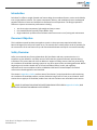
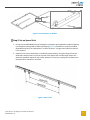
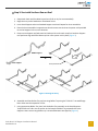
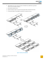
Polar Bear® III for 10 Degree Installation Manual Document Number 9910024 Rev A March 2014 panelclaw.com Revision History Rev ECO # Date Description of Changes 01 TBD 02-FEB-14 Initial Draft A C00336 06-MAR-14 First release of Polar Bear III 10 degree Approved By CA Table of Contents Revision History ............................................................................................................................................ 2 Introduction .................................................................................................................................................. 3 Document Objective ..................................................................................................................................... 3 Safety Overview ............................................................................................................................................ 3 Parts and Hardware ...................................................................................................................................... 4 Parts and Hardware ...................................................................................................................................... 5 Required Tools .............................................................................................................................................. 5 Installation .................................................................................................................................................... 5 Step 1: Attach Claws to Modules (Prep) ....................................................................................................... 5 Step 2: Set up Spacer Stick ............................................................................................................................ 6 Step 3: Start with Southern Row on Roof ..................................................................................................... 7 Step 4: Set-up North-South Column ............................................................................................................. 9 Step 5: Complete Array with Row by Row Installation ............................................................................... 10 Appendix A: Safety ...................................................................................................................................... 12 Polar Bear III 10 Degree Installation Manual 9910024 Rev A 2 Introduction Polar Bear® III offers a straight-forward roof mount design that combines features, service and reliability into a single platform solution. The system components, delivery, and installation process are designed together to deliver a lower total installed cost and better service experience. The design emphasizes features to improve construction performance including: • • • Just three major components, light-weight and easy to move Pre-assembled bolts to quickly mount Ballast Trays Single-module tilt-up feature that facilitates must-have access to roof, wiring and maintenance Document Objective This installation manual has been put together to assist in the proper steps required to build a Polar Bear III 10 Degree flat roof mount system array. The manual covers a best-practice order of assembly for the construction of the roof mount array and contains detailed notes and tips for a successful assembly. Safety Overview Safety is an essential part of every photovoltaic (PV) installation and every construction site. It is imperative to plan ahead for any safety concerns and hazards to promote safe work practices during installation. This section does not claim to address or support all safety concerns that may arise during the installation of PanelClaw mounting systems or any other aspect of the work being performed. Before beginning work, installers should refer to all local and federal safety, health, and regulatory requirements to assure compliance. Refer to OSHA Part 1926 and its related Subparts for federal construction related regulations and standards. The section in Appendix A: Safety outlines some of the obvious / major hazards that could exist during the installation of PanelClaw products, and are divided to bring a level of clarity to such hazards. Some sections do not apply to all PanelClaw product lines and such exclusions are noted within each section. PRIOR TO INSTALLATION, READ THE SAFETY PROVISIONS ATTACHED IN Appendix A: Safety AND REVIEW THE INSTALLATION MANUAL IN ITS ENTIRETY. Polar Bear III 10 Degree Installation Manual 9910024 Rev A 3 Parts and Hardware Major Components Supports Claw North Support Middle Support Ballast Trays Short Ballast Tray Long Ballast Tray South Support Hardware Kits Claw Fastener Kit Ballast Ballast Tray Nut Kit Ballast Tray Bolt Kit Optional Ballast Block (Customer supplied) Polar Bear III 10 Degree Installation Manual 9910024 Rev A Mechanical Attachment (Coming soon) 4 Parts and Hardware Supports Support unit with pre-installed integrated recycled rubber pads and 1/4-20 rivnuts Claw G90 Galvanized Steel module Claw Ballast Trays Connects Supports and captures 4”x8”x16” ballast Claw Fastener Kit Serrated flange nuts 1/4-20 Stainless Steel 18-8 Hex head cap screw 1/4-20 x 1.75” Stainless Steel 18-8 Hex head cap screw 1/4-20 x 0.5” Stainless Steel 18-8 Ballast Tray Nut Kit Serrated flange nuts 1/4-20 Stainless Steel 18-8 Ballast Tray Bolt Kit Hex head cap screw 1/4-20 x 0.5” Stainless Steel 18-8 Ballast Block Solid cap concrete roof paver, conforms to ASTM C 1491-03 standard Mechanical Attachment (optional) Coming soon. Required Tools • 3/8” drive torque wrench (settings available up to 10 ft-lbs) • 3/8” deep socket (bolts) • 7/16” deep socket (nuts) • Spacer Stick (supplied) Installation Step 1: Attach Claws to Modules (Prep) 1. Lay module, glass side down, on work surface. 2. Place Claw over appropriate mounting hole, resting Claw flange against outside edge of module. 3. With one hand, insert bolt through Claw and module holes. 4. With other hand, reach under the module frame flange and thread nut onto bolt until snug. 5. Press Claw firmly against module frame and tighten bolt to 8 ft-lbs of torque (Figure 1). 6. Repeat Steps 2 through 5 for the other three Claws. Polar Bear III 10 Degree Installation Manual 9910024 Rev A 5 Figure 1 Claw Placement on Module Step 2: Set up Spacer Stick 1. Consult the provided Ballast Layout Drawing for the Support spacing between modules (Spacing L) and Support spacing under modules (Spacing Q) (Figure 2). Dimensions L and Q are module dependent and vary from manufacturer. In some scenarios L is longer than Q while for others it is the opposite. 2. Reference the Q and L dimensions on the Ballast Layout Drawing. Using the longer of the two dimensions attach a Claw to a hole at one end of the Spacer Stick. Set the longer claw to the dimension specified. Repeat for the smaller dimension. If the Q or L spacing has interference on the Spacer Stick relocate the first Claw. Figure 2 Spacer Stick Polar Bear III 10 Degree Installation Manual 9910024 Rev A 6 Step 3: Start with Southern Row on Roof 1. Snap North-South and East-West layout lines (chalk or dry line recommended). 2. Begin the array at the Southeast or Southwest corner. 3. Insert South Support tube into Standard Support south end. Repeat for three assemblies. 4. Place the three assemblies in approximate locations east-west and use the spacer stick provided to set the Supports in the correct locations. 5. Eastern most Support roof pads must be lined up with north-south snap line. Southern Support roof pad must align with East-West snap line. Leave spacer stick in place (Figure 3). Middle Support x3 South Support Array Perimeter Figure 3 Starting the Array 6. Assemble one Short Ballast Tray and one Long Ballast Tray using the ¼-20 x 0.5” serrated flange bolts. Bolts must be torqued to 4 ft-lbs. 7. Using appropriate Ballast Tray slots, bolt the Ballast Tray assembly to the South Supports. Torque bolts to 4 ft-lbs. Use the spacer stick to keep the Ballast Tray perpendicular to the Supports. Note: ensure Long Ballast tray is centered between two supports (Figure 4). Polar Bear III 10 Degree Installation Manual 9910024 Rev A 7 Figure 4 Ballast Tray to South Supports 8. Repeat Steps 3 through 7 but do not use another Short Ballast Tray until you reach the last module in the row. 9. Install required ballast into southern Ballast Trays. 10. Carry module to south-east (or west) corner. 11. Using Figure 5 align Claws over South Support mounting holes. Insert bolts through Claw and Support mounting hole. Finger-tighten nuts onto bolts. 12. Lower module onto upper mounting hole of the Standard Support. Some adjustment to the Standard Support location may be necessary to align with Claw. Insert bolts through Claw and upper mounting hole of the Standard Support. 13. Tighten all four mounting bolts to 8 ft-lbs of torque. 14. Repeat Steps 9 through 14 for southern row. Be sure to use inter-column spacer, a standard support turned upside down between modules, to ensure that a 1”spacing is maintained. Polar Bear III 10 Degree Installation Manual 9910024 Rev A 8 x4 x4 1 x2 2 1 2 x2 Figure 5 Attach Module to Supports Step 4: Set-up North-South Column 1. Carry one module and two Standard Supports to Southeast or Southwest corner. Set Standard Supports down within arm’s reach behind the previous row (Figure 6). 2. Connect module Claws to lower mounting holes on Middle Support. Finger-tighten bolts. 3. Tilt module down and connect module Claw to the high side of the Standard Support that was brought over. Finger-tighten nut and bolt. Repeat Claw connection for the other Support. Be sure to align outer Standard Support pads with North-South snap line. 3. Tighten all four mounting hardware to 8 ft-lbs of torque. 4. Repeat Steps 1 through 5 for remainder of column, with the exception of the Northern-most module. For this location use two North Supports. If using High Capacity North Supports see High Capacity North Row Installation steps. Polar Bear III 10 Degree Installation Manual 9910024 Rev A 9 1 2 Figure 6 North-South Column Setup Step 5: Complete Array with Row by Row Installation With the East-West and North-South row and column now in place you may begin the interior installation for the remaining array. The following steps assume a row by row installation (see Figure 7). 1. Assemble one Short Ballast Tray and one Long Ballast Tray using the ¼-20 x 0.5” serrated flange bolts. Bolts must be torqued to 4 ft-lbs. 2. Using appropriate Ballast Tray slots, place the Ballast Tray assembly onto the pre-installed bolts of the Standard Supports on the south row. Thread the serrated-flange nut onto the Support Bolt and torque to 4 ft-lbs. Note: ensure Long Ballast tray is centered between two Supports. 3. Continue to install Long Ballast Trays to all Standard Supports on the south row. Use slots on Ballast Tray to set the Ballast Tray onto the pre-installed bolts. Be sure to use the appropriate Ballast Tray slots. Polar Bear III 10 Degree Installation Manual 9910024 Rev A 10 4. Tighten Ballast Tray nuts to 4 ft-lbs of torque. The Ballast Tray installation may proceed concurrently with module installation. 5. Place ballast into Ballast Trays. 6. Repeat installation sequence in Step 4 continuing East-West instead of North-South. 7. Continue with Ballast Tray and Ballast installation to complete the array. Figure 7 Row by row installation Polar Bear III 10 Degree Installation Manual 9910024 Rev A 11 Appendix A: Safety The subsections below outline some of the obvious / major hazards that could exist during the installation of PanelClaw products, and are divided to bring a level of clarity to such hazards. Some sections do not apply to all PanelClaw product lines and such exclusions are noted within each section. Electrical Hazards: PanelClaw products are purely mechanical and do not contain any electrically live parts. When a photovoltaic module is exposed to sunlight it is electrically live and cannot be turned off. As soon as modules are installed using a PanelClaw system, an electrical shock hazard is present. All personnel on site should coordinate to ensure that such electrical hazards are clearly communicated. It is advised, at a minimum, that all personnel utilize caution and proper Personal Protective Equipment as outlined in that section. Only electrically qualified personnel should perform PV module installation. Refer to OSHA Part 1926 Subpart K – Electrical and NFPA 70E for additional information. Fall Hazards: This section only applies to Grizzly Bear®, Polar Bear®, and Kodiak Bear™ products installed on locations six feet or higher above grade. Proper fall protection should be in place at all work sites. There are many fall protection solutions readily available to help reduce exposure to fall hazards. These may include personal fall arrest systems, safety nets, guardrails, and flagged setbacks from all roof edges as outlined in OSHA Part 1926 Subpart M – Fall Protection. Trip Hazards: All PanelClaw arrays have elevated components that are installed above grade or above a roof surface. Such hazards should be identified and caution should be taken to avoid tripping over such components. Refer to the Fall Hazards section specifically if working with the Grizzly Bear, Polar Bear, and Kodiak Bear product lines. Make sure to pick up and not drag your feet when working on site, and always pay attention to your path of movement to note any obstructions that could create a trip hazard. Lifting Hazards: The PanelClaw installation process involves lifting of heavy items that could lead to personal injury and damage to property. All personnel should be trained in the proper procedures for manually lifting. Evaluate an object’s size and weight prior to lifting, and follow these general guidelines for lifting: 1. Assess the lift and know the object weight. 2. Bend at the knees and get a good grip. 3. Keep back straight and lift straight up with legs without twisting. It is important to lift with the legs and not the back. 4. If an object is too large or heavy, ask for help and do not attempt to lift by yourself. In the case that mechanical assistance (e.g. crane, forklift, etc.)is required to complete the lifting operations, all machine operators of such devices should be licensed and trained. Material Handling: All PanelClaw parts and components are made of aluminum and steel alloys and utilize stainless steel assembly hardware. These materials are considered non-toxic and require no special handling procedures. Metal components may have sharp edges, so be sure to handle with care and utilize proper personal protection equipment, especially gloves, during handling. Refer to OSHA Part 1926 Subpart H – Materials Handling, Storage, Use, and Disposal for additional information. Personal Protective Equipment (PPE): All personnel should utilize and implement proper PPE per OSHA requirements. Refer to OSHA requirements for proper use and implementation of PPE. The following Polar Bear III 10 Degree Installation Manual 9910024 Rev A 12 items are suggested as a minimum to avoid injury based on the installation procedure outlined in this manual: 1. 2. 3. 4. 5. 6. 7. Appropriate work clothing Electrically insulated hard hat Protective eyewear EH rated safety boots Gloves High-visibility safety vest Hearing protection If any PPE appears to be defective, stop the use of such equipment immediately, and ensure it is replaced before work continues. Refer to OSHA Part 1926 Subpart E – Personal Protective and Life Saving Equipment for additional information. Hand and Power Tools: Access to all hand and power tools should be regulated and controlled at all times on site to prevent improper use and related injuries. When not in use, all equipment should be stored in a secured location. Only personnel who have been properly trained in the safe operation of any potentially dangerous tool should be allowed access. All required tools to perform the installation of PanelClaw racking are outlined in the installation procedure. All tools should be inspected daily and before use by the operator. If any tool appears to be defective, stop the use of such equipment immediately, and ensure it is replaced before work continues. Electrical power tools should follow proper lock-out tag-out procedures per OSHA requirements. Refer to OSHA Part 1926 Subpart I – Tools – Hand and Power for additional information. Polar Bear III 10 Degree Installation Manual 9910024 Rev A 13