1
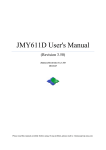
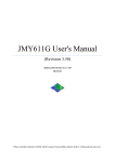
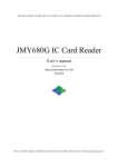
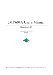
MR761UA User's Manual (Revision 3.31) Jinmuyu Electronics Co. LTD 2011/7/21 Please read this manual carefully before using. If any problem, please mail to: [email protected] MR761UA USB HID interface Contactless IC Card Reader user’s manual http://www.jinmuyu.com Contents 1 2 3 4 5 6 7 Overview ................................................................................................................................................. 2 Technical parameters ............................................................................................................................... 2 Cards supported ....................................................................................................................................... 3 3.1 ISO14443A.............................................................................................................................. 3 3.2 ISO7816 .................................................................................................................................. 3 Model of the reader ................................................................................................................................. 3 4.1 Model format ........................................................................................................................... 3 4.2 Model description .................................................................................................................... 3 4.2.1 Product code .................................................................................................................... 3 4.2.2 Device class ..................................................................................................................... 4 4.2.3 Communication port ........................................................................................................ 4 4.2.4 Supported card type ......................................................................................................... 4 4.2.5 Color of enclosure ........................................................................................................... 4 4.2.6 ODM code ....................................................................................................................... 4 4.3 Model available ....................................................................................................................... 4 DIP switch configuration......................................................................................................................... 5 Configuration software instruction .......................................................................................................... 5 6.1 Reader installation ................................................................................................................... 5 6.2 Software connects to the device .............................................................................................. 7 6.3 Data output configuration instruction ...................................................................................... 8 6.3.1 Card SNR output configuration ....................................................................................... 9 6.3.2 Card data output configuration ...................................................................................... 10 6.3.2.1 Start data configuration ......................................................................................... 10 6.3.2.2 Continuous mode ................................................................................................... 10 6.3.2.3 Array mode ............................................................................................................ 11 6.3.2.4 Extra key additional............................................................................................... 11 6.3.3 Parameter downloads .................................................................................................... 12 6.4 Device working ..................................................................................................................... 13 6.5 Reset the configuration parameter ......................................................................................... 14 Application sample ................................................................................................................................ 15 Copyright © 2003-2011 Jinmuyu Electronics Co., LTD. All rights reserved. 1/17 MR761UA USB HID interface Contactless IC Card Reader user’s manual http://www.jinmuyu.com 1 Overview MR761UA desktop contactless IC card reader use USB interface (HID standard). In the systems of Windows, Linux and other PC systems support USB keyboard, the reader simulate the USB keyboard to output the card data.We supply a configuaration software. Under the the software, user could configuar complex read card method to implement many type of uses. The reader supports the ISO15693 compliant tags. The output data could be UID and/or card data. 2 Technical parameters PCD: Working frequency: RF protocol: Operating distance: SAM slots: Display: Buzzer: Interface: Power supply: Power consumption: Dimension: Weight: Operating temperature: Storage temperature: PC software: ISP: RoHS: NXP MF RC522 13.56MHz ISO14443A 80mm (Mifare One, typical) 2 slots, full function support ISO7816, only for ODM 1 tricolor LED Build in USB HID standard, keyboard simulator DC5V ±10%, USB power supply 0.6W 123mm * 88mm * 25mm About 100g -25 ~ +85°C -40 ~ +125°C MR76x Config Tools, download from http://www.jinmyu.com Support Compliant Copyright © 2003-2011 Jinmuyu Electronics Co., LTD. All rights reserved. 2/17 MR761UA USB HID interface Contactless IC Card Reader user’s manual http://www.jinmuyu.com 3 Cards supported 3.1 ISO14443A Mifare One S50 Mifare One S70 Mifare One Mini Mifare Ultra Light Desfire (UID) Mifare Plus (UID) ISO14443-4 (T=CL) TYPE A dual interface CPU Card (UID) 3.2 ISO7816 Any type of contact smart cards according to ISO7816, support any baud rate reset and any baud rate operation (by PPS) 4 Model of the reader 4.1 Model format This is the model format of Master Reader series contactless card reader/writer: 1 2 3 4 5 6 MR XXX X X X -XXX 1: Product code; 2: Device class; 3: Communication port; 4: Supported card type; 5: Color of enclosure; 6: ODM code; 4.2 Model description 4.2.1 Product code The code of Master Reader series contactless card reader is: MR Copyright © 2003-2011 Jinmuyu Electronics Co., LTD. All rights reserved. 3/17 MR761UA USB HID interface Contactless IC Card Reader user’s manual http://www.jinmuyu.com 4.2.2 Device class 600: Desktop reader/writer with LED digital display 701: Desktop reader/writer 730: Ethernet desktop reader/writer 760: HID keyboard simulator interface desktop reader, support ISO15693 only 761: HID keyboard simulator interface desktop reader, support ISO14443A and ISO14443B 780: High performance desktop reader/writer, support ISO7816 fully 790: USB PC/SC interface desktop reader/writer 800: High performance USB PC/SC interface desktop reader/writer with LCD display 810: High performance USB PC/SC interface desktop reader/writer 4.2.3 Communication port S: RS232C interface, power supply from USB R: RS485 interface, power supply by wire connection U: USB interface E: Ethernet interface, power supply by AC adaptor 4.2.4 Supported card type A: ISO14443A, Mifare classic and ISO7816 C: ISO14443A, ISO14443B, Mifare classic and ISO7816 G: ISO15693 and ISO7816 H: ISO14443A, ISO14443B, ISO15693, Mifare classic and ISO7816 4.2.5 Color of enclosure W: white (if blank, default white) B: black 4.2.6 ODM code This part is for ODM customer only. It is 3 digital codes like 001, 002... 4.3 Model available The models below are available for supply: MR761UA MR761UC Copyright © 2003-2011 Jinmuyu Electronics Co., LTD. All rights reserved. 4/17 MR761UA USB HID interface Contactless IC Card Reader user’s manual http://www.jinmuyu.com 5 DIP switch configuration ON (default) OFF SW1 Working mode depends on the software Working mode depends on SW2 SW2 Reader on the configuration mode Reader on the reading card mode SW3 - - SW4 - - 6 Configuration software instruction 6.1 Reader installation The reader interface is USB HID class. The driver installation wills automatic process by OS. User need not do anything except connect the reader. Then check the attributes of “USB Human Interface Device”: Copyright © 2003-2011 Jinmuyu Electronics Co., LTD. All rights reserved. 5/17 MR761UA USB HID interface Contactless IC Card Reader user’s manual Copyright © 2003-2011 Jinmuyu Electronics Co., LTD. All rights reserved. http://www.jinmuyu.com 6/17 MR761UA USB HID interface Contactless IC Card Reader user’s manual http://www.jinmuyu.com 6.2 Software connects to the device Open the configuration tool. Then click the “Connect” button. Successfully connect as following: The dialog box will prompt the supported card types. Copyright © 2003-2011 Jinmuyu Electronics Co., LTD. All rights reserved. 7/17 MR761UA USB HID interface Contactless IC Card Reader user’s manual http://www.jinmuyu.com 6.3 Data output configuration instruction Taking ISO14443A tag as an example, set the output card number and card data. As the picture, the supported card is ISO14443A, and output select is Card SNR, Card Data Mifare S50/S70 and UltraLight Copyright © 2003-2011 Jinmuyu Electronics Co., LTD. All rights reserved. 8/17 MR761UA USB HID interface Contactless IC Card Reader user’s manual http://www.jinmuyu.com 6.3.1 Card SNR output configuration Click “SNR” tab to set the Card SNR, as following: Card number order set: Card Number format set: CapsLk set: Extra key set: Set MSB first or LSB first output Set HEX or DEC Set the letter of card number in Caps or lower case After card number output, select output key assignments (4 optional keys: Tab, Enter, Down Arrow and Page Down) and typing numbers. Copyright © 2003-2011 Jinmuyu Electronics Co., LTD. All rights reserved. 9/17 MR761UA USB HID interface Contactless IC Card Reader user’s manual http://www.jinmuyu.com 6.3.2 Card data output configuration 6.3.2.1 Start data configuration Click “Mifare S50/S70” tab to set the card data output configuration. Two modes (Mode1, Mode2) can be select. Select the key assignment in “Every Block End” and “Data End”, as following: 6.3.2.2 Continuous mode Name the start byte of the start block, then output, till to the end byte of the named end block, as the chart: Byte Block 00 01 02 03 04 05 6 7 8 9 10 11 12 13 14 15 Block0 00 01 02 03 04 05 06 07 08 09 0A 0B 0C 0D 0E 0F Block1 10 11 12 13 14 15 16 17 18 19 1A 1B 1C 1D 1E 1F Block2 20 21 22 23 24 25 26 27 28 29 2A 2B 2C 2D 2E 2F If set the following parameters: Start sector = 00 End sector = 00 Start block = 00 End block = 02 Start byte = 07 End byte = 06 Copyright © 2003-2011 Jinmuyu Electronics Co., LTD. All rights reserved. 10/17 MR761UA USB HID interface Contactless IC Card Reader user’s manual http://www.jinmuyu.com Then the output data is the red data in the chart: 07 08 09 0A 0B 0C 0D 0E 0F 10 11 12 13 14 15 16 17 18 19 1A 1B 1C 1D 1E 1F 20 21 22 23 24 25 26 6.3.2.3 Array mode Name the start block and end block, then start to output the data from the start byte to the end byte, as the chart: Byte Block 00 01 02 03 04 05 6 7 8 9 10 11 12 13 14 15 Block0 00 01 02 03 04 05 06 07 08 09 0A 0B 0C 0D 0E 0F Block1 10 11 12 13 14 15 16 17 18 19 1A 1B 1C 1D 1E 1F Block2 20 21 22 23 24 25 26 27 28 29 2A 2B 2C 2D 2E 2F If set the following parameters: Start sector=00 End sector=00 Start block=00 End block=02 Start byte=03 End byte=09 Then the output data is the red data in the chart: 03 04 05 06 07 08 09 13 14 15 16 17 18 19 23 24 25 26 27 28 29 6.3.2.4 Extra key additional CapsLk setting: Extra key setting: Every block end: Data end: Set CapsLk to configure the output of part of card number letter in Upper-case or Lower-case format. Set the key in two positions (Every block end and Data End) after the card number output. Then set the output key assignments (4 optional keys: Tab, Enter, Down and Page Down) and typing number. Set the output extra key after every block output ends. Set the output extra key after data output ends. Copyright © 2003-2011 Jinmuyu Electronics Co., LTD. All rights reserved. 11/17 MR761UA USB HID interface Contactless IC Card Reader user’s manual http://www.jinmuyu.com 6.3.3 Parameter downloads After finish all the configuration item, click “DownLoad” to download the parameters, if success, as following: Copyright © 2003-2011 Jinmuyu Electronics Co., LTD. All rights reserved. 12/17 MR761UA USB HID interface Contactless IC Card Reader user’s manual http://www.jinmuyu.com If download success, and then click “Reset” to restart the device. After restart, the computer and device disconnect. Then the computer will re-identify the device and turn to the reading card mode, as following: 6.4 Device working Once the computer re-identifies the device, it will only identify one device. As following: Then according to the set parameter, the device will output the data after read success. Copyright © 2003-2011 Jinmuyu Electronics Co., LTD. All rights reserved. 13/17 MR761UA USB HID interface Contactless IC Card Reader user’s manual http://www.jinmuyu.com 6.5 Reset the configuration parameter If the output data changed, then need to reset the configuration parameters. Please pull the DIP switch SW1 to OFF, and SW2 to ON. After the device power up and start, user can normally setup the device parameter. When parameter download finishes, pull the DIP switch SW1 to ON, then click “Reset” and restart the device, the device will turn into working mode. Setting steps: Step 1: Pull SW1 to OFF, SW2 stay in ON, device power up. Step 2: Set the configuration parameter, download parameter (see the Chapter 5.3) Step 3: Pull SW1 to ON. Step 4: Click “Reset” to restart the device. Copyright © 2003-2011 Jinmuyu Electronics Co., LTD. All rights reserved. 14/17 MR761UA USB HID interface Contactless IC Card Reader user’s manual http://www.jinmuyu.com 7 Application sample E.g., as the chart, the RED NUMBER stores in the Block 4~6: Byte Block 00 01 02 03 04 05 6 7 8 9 10 11 12 13 14 15 Block4 00 01 02 03 04 05 06 07 08 09 0A 0B 0C 0D 0E 0F Block5 10 11 12 13 14 15 16 17 18 19 1A 1B 1C 1D 1E 1F Block6 20 21 22 23 24 25 26 27 28 29 2A 2B 2C 2D 2E 2F Set the “System Config” as following: Not select Card SNR, not output the card number Select Card data and Mifare S50/S70 Set the Mifare S50/S70 as following: Select Mode 1, and set the continuous output mode Set: Start sector=01 Start block=00 Start byte=07 End sector=01 End Block=02 End Byte=06 Copyright © 2003-2011 Jinmuyu Electronics Co., LTD. All rights reserved. 15/17 MR761UA USB HID interface Contactless IC Card Reader user’s manual http://www.jinmuyu.com Select data to output Select Key type: Key A Set Key: FF FF FF FF FF FF Set CapsLk to select the Capital letter output. Set Every Block End, the Key of Every Block End is None Key=None Num=1 Set Data End, the Key of Data End is Enter, Num is 1. Key=Enter Num=1 As the above setting, the reader will output the Red data in the chart. Copyright © 2003-2011 Jinmuyu Electronics Co., LTD. All rights reserved. 16/17