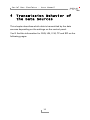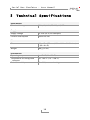
1
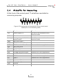
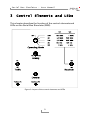
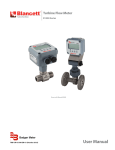
Serial Bus Simulator
Data Stream Generator for Serial Bus
Protocols
User Manual
Serial Bus Simulator – User Manual
Products taken into account
Product Name
Model
Item Number
Serial Bus Simulator
1.1
IPEH-003050
Product names mentioned in this manual may be the trademarks or registered
trademarks of their respective companies. They are not explicitly marked by “™” and
“®”.
© 2009 PEAK-System Technik GmbH
PEAK-System Technik GmbH
Otto-Roehm-Strasse 69
64293 Darmstadt
Germany
Phone: +49 (0)6151 8173-20
Fax:
+49 (0)6151 8173-29
www.peak-system.com
[email protected]
Issued 2009-02-27
2
Serial Bus Simulator – User Manual
Contents
1
1.1
1.2
1.3
2
2.1
2.2
2.3
2.4
3
3.1
3.2
3.3
3.4
3.5
4
4.1
4.2
4.3
4.4
4.5
5
Introduction
4
Properties at a Glance
Prerequisites for the Operation
Scope of Supply
Connectors
4
5
5
6
USB Cable for Power Supply
GND Socket
CAN/LIN D-Sub Connector
Pickoffs for Measuring
Control Elements and LEDs
Operating Mode (Rotary Switch)
Analog (Potentiometer)
Baudrate (Selector Switch)
Traffic (Selector Switch/LED)
Destroy (Push Button/LED)
Transmission Behavior of the Data Sources
CAN
LIN
V.24
I2C
SPI
6
6
7
8
9
10
10
11
11
11
12
13
14
15
16
17
Technical Specifications
3
18
Serial Bus Simulator – User Manual
1
Introduction
The Serial Bus Simulator (SBS) generates data streams for several
serial bus types. The data streams can be used e.g. for
demonstrations and validations of measuring systems.
1.1
Properties at a Glance
Generates data streams for the following serial bus systems:
• CAN
• LIN
• V.24 (RS-232)
• I2 C
• SPI
2 different transfer rates for each bus system
Disengageable transmission of data frames
Specific generation of defect data frames
Pin assignment of D-Sub CAN connector according to
CiA 102 DS
Generation of an analog voltage for testing (e.g. trigger)
Pickoffs for oscilloscope probes
Desk-type casing
Power supply via USB connection
4
Serial Bus Simulator – User Manual
1.2
Prerequisites for the Operation
The following prerequisites must be given, so that the SBS can be
used properly:
Vacant USB port on an external device (e.g. measuring
instrument, computer, power supply unit) for the power supply
of the SBS (about 125 mA current consumption)
1.3
Scope of Supply
The scope of supply normally consists of the following parts:
Serial Bus Simulator (desk-type casing) with USB connection
cable
CD with user manual in PDF format
5
Serial Bus Simulator – User Manual
2
Connectors
This chapter describes the pin assignment of each connector on the
rear and on the control panel of the Serial Bus Simulator (SBS).
2.1
USB Cable for Power Supply
The USB cable is used for the simplified connection of the power
supply (5 V). The USB data lines are unused.
Plug the USB connector into any USB port of an external device
(e.g. measuring instrument, computer, power supply unit).
The green LED at the rear of the casing is on, when the 5-Volt
supply is present.
The current consumption of the SBS is about 125 mA.
2.2
GND Socket
In order to establish a ground connection between the SBS and a
measuring set-up a 4-mm socket is available at the rear of the
casing. A cable with banana plug can be used here (not included).
6
Serial Bus Simulator – User Manual
2.3
CAN/LIN D-Sub Connector
The 9-pin D-Sub male connector on the rear of the casing includes
the differential CAN signal (ISO 11898-2) and the LIN signal as well
as a ground line. These signals are also available at the pickoffs on
the control panel of the SBS.
Figure 1: Pin assignment of the D-Sub male connector for CAN and LIN
The CAN bus is terminated internally between the two signal lines
CAN_L and CAN_H with 120 Ω.
The SBS is configured as LIN master and the LIN bus is terminated
with 1 kΩ accordingly.
7
Serial Bus Simulator – User Manual
2.4
Pickoffs for Measuring
At the front of the control panel 17 pickoffs are available for
measuring purposes.
Figure 2: Pin assignment of the pickoffs on the control panel
(description in the following table)
Label
Function
Remark
+5V
Power supply 5 V
Via 100 Ω, not intended to drive
electrical loads
GND
Ground
Analog
Analog voltage 0 - 3.3 V from
potentiometer
Via 100 Ω, not intended to drive
electrical loads
SSEL
SPI: Slave Select
MOSI
SPI: Master Out – Slave In
MISO
SPI: Master In – Slave Out
SCK
SPI: Serial Clock
SDA
I2C: Serial Data
SCL
I2C: Serial Clock
RxD
V.24/RS-232: Receive Data
TxD
V.24/RS-232: Transmit Data
IO-0
GPIO-0
Reserved for future applications
IO-1
GPIO-1
Reserved for future applications
CAN_L
CAN: Low signal
CAN_H
CAN: High signal
GND
Ground
LIN
LIN signal
Reserved for future applications
Reserved for future applications
8
Serial Bus Simulator – User Manual
3
Control Elements and LEDs
This chapter describes the function of the control elements and
LEDs on the Serial Bus Simulator (SBS).
Figure 3: Layout of the control elements and LEDs
9
Serial Bus Simulator – User Manual
3.1
Operating Mode (Rotary Switch)
The rotary switch activates one out of five sources for serial data:
CAN (Controller Area Network)
LIN (Local Interconnect Network)
V.24 (standard for data remote transfer, related to RS-232)
I2C (Inter-Integrated Circuit)
SPI (Serial Peripheral Interface)
In position OFF no serial data is generated. However, the SBS is still
alive. Analog functions, like the 3.3 Volts at the potentiometer and
the 5-Volt output, are active.
The output of each data source is described in chapter 4 on page 12.
3.2
Analog (Potentiometer)
The potentiometer has several functions:
When generating data errors (Destroy push button), the position
of the error within the data frame can be adjusted.
The variable data byte within the data frames can be varied from
0x00 to 0xFF.
A voltage from 0 to 3.3 Volts is provided at the pickoff Analog
for measuring purposes.
Note: The voltage at the pickoff Analog is not intended to drive
electrical loads.
10
Serial Bus Simulator – User Manual
3.3
Baudrate (Selector Switch)
The selector switch determines the transfer rate for each data
source. The transfer rates are defined as follows:
Data source
CAN
Transfer rate
low
high
125 kbit/s
1 Mbit/s
LIN
9600 Baud
19200 Baud
V.24
9600 Baud
19200 Baud
I2C
100 kHz
400 kHz
SPI
1 MHz
4 MHz
3.4
Traffic (Selector Switch/LED)
When switched to On, additional data load is activated for the
selected data source. Usually three frames are transmitted cyclically
in turn every 50 ms.
The green LED flashes in the rhythm of the additional frames being
transmitted.
3.5
Destroy (Push Button/LED)
By pressing this push button an additional frame with a protocol
violation is generated. This frame should be recognized as
erroneous at measurements (except for SPI).
The red LED flashes, when an erroneous frame is transmitted
(pressed push button).
11
Serial Bus Simulator – User Manual
4
Transmission Behavior of
the Data Sources
This chapter describes which data is transmitted by the data
sources depending on the settings on the control panel.
You'll find the information for CAN, LIN, V.24, I2C and SPI on the
following pages.
12
Serial Bus Simulator – User Manual
4.1
CAN
CAN data frames are generated, when the rotary switch Operating
Mode is turned to the position CAN. The ACK bit (Acknowledge) is
generated by the SBS itself, thus a listen-only operation is possible.
The selector switch Baudrate changes the transfer rate to the value
given on the control panel (125 kbit/s or 1 Mbit/s).
When pressing the Destroy push button, the data source generates
a correct CAN frame superimposed by a long dominant gap to force
an error.
The position of the dominant gap within the CAN frame can be
adjusted with the Analog potentiometer. The gap length depends
on the selected transfer rate. So, different types of errors are
generated, e.g. CRC or Stuff errors.
The transmitted CAN frame (without error) would be:
CAN ID
Length Data (hex)
0x00000666 (29 bit)
8
01 23 45 67 89 AB CD EF
If the Traffic selector switch is in position On, three additional CAN
frames are transmitted cyclically in turn every 50 ms:
CAN ID
Length Data
Data (hex)
0x00000200 (29 bit)
4
“C” “A” “N” [Analog]
43 41 4E [00 … FF]
0x300 (11 bit)
6
“L” “e” “C” “r” “o” “y”
4C 65 43 72 6F 79
0x00000400 (29 bit)
4
“P” “E” “A” “K”
50 45 41 4B
The value [Analog] is determined by the position of the Analog potentiometer.
13
Serial Bus Simulator – User Manual
4.2
LIN
LIN data frames are generated, when the rotary switch Operating
Mode is turned to the position LIN.
The selector switch Baudrate changes the transfer rate to the value
given on the control panel (9600 bit/s or 19200 bit/s).
When pressing the Destroy push button, the data source generates
a LIN frame with illegal header parity. The error is generated with
the following composition: header parity XOR 0x40
The transmitted LIN frame (without error) would be:
LIN ID
Length Data (hex)
0x0F (15 dec)
4
00 55 AA FF
If the Traffic selector switch is in position On, three additional LIN
frames are transmitted cyclically in turn every 50 ms:
LIN ID
Length Data
Data (hex)
0x1E (30 dec)
4
“L” “I” “N” [Analog]
4C 49 4E [00 … FF]
0x2D (45 dec)
6
“L” “e” “C” “r” “o” “y”
4C 65 43 72 6F 79
0x3C (60 dec)
4
“P” “E” “A” “K”
50 45 41 4B
The value [Analog] is determined by the position of the Analog potentiometer.
14
Serial Bus Simulator – User Manual
4.3
V.24
V.24/RS-232 data frames are generated, when the rotary switch
Operating Mode is turned to the position V.24. The data format is:
8 data bits, no parity bit, 1 stop bit (8N1)
The selector switch Baudrate changes the transfer rate to the value
given on the control panel (9600 bit/s or 19200 bit/s).
When pressing the Destroy push button, the data source generates
a 5 byte long frame with illegal stop bit in the third frame (“c”).
The position of the Analog potentiometer doesn't have any
influence on the generation of the errors.
The transmitted V.24 frame (without error) would be:
Length Data
Data (hex)
5
61 62 63 64 0D
“a” “b” “c” “d” CR
If the Traffic selector switch is in position On, three additional V.24
frames are transmitted cyclically in turn every 50 ms:
Length Data
Data (hex)
5
“V” “2” “4” [Analog] CR
56 32 34 [00 … FF] 0D
7
“L” “e” “C” “r” “o” “y” CR
4C 65 43 72 6F 79 0D
5
“P” “E” “A” “K” CR
50 45 41 4B 0D
The value [Analog] is determined by the position of the Analog potentiometer.
15
Serial Bus Simulator – User Manual
4.4
I2C
I2C data frames are generated, when the rotary switch Operating
Mode is turned to the position I2C.
The selector switch Baudrate changes the transfer rate to the value
given on the control panel (100 kHz or 400 kHz).
When pressing the Destroy push button, the data source generates
an 8 byte long frame with missing ACK bits at the characters “o”
and “c”.
The position of the Analog potentiometer doesn't have any
influence on the generation of the errors.
The transmitted I2C frame (without error) would be:
Data
Data (hex)
0xA0 0x00 0x00 “n” “o” “a” “c” “k”
A0 00 00 6E 6F 61 63 6B
The first three bytes represent the command “EEPROM write to address 0x0000”.
If the Traffic selector switch is in position On, three additional I2C
frames are transmitted cyclically in turn every 50 ms:
Data
Data (hex)
0xA0 0x01 0x00 “I” “2” “C” [Analog]
A0 01 00 49 32 43 [00 … FF]
0xA0 0x01 0x80 “L” “e” “C” “r” “o” “y”
A0 01 80 4C 65 43 72 6F 79
0xA0 0x02 0x00 “P” “E” “A” “K”
A0 02 00 50 45 41 4B
The value [Analog] is determined by the position of the Analog potentiometer.
16
Serial Bus Simulator – User Manual
4.5
SPI
SPI data frames are generated, when the rotary switch Operating
Mode is turned to the position SPI. Data is transmitted via the pin
MasterOut-SlaveIn (MOSI). The pin MasterIn-SlaveOut (MISO) is not
used by this application.
The selector switch Baudrate changes the transfer rate to the value
given on the control panel (1 MHz or 4 MHz).
When pressing the Destroy push button, the data source generates
a 4 byte long frame. Since the SPI bus doesn't have a stringent
protocol, a frame cannot be destroyed and is therefore always
decoded as correct. It can be used for trigger purposes.
The transmitted SPI frame (always correct) is:
Data
Data (hex)
0x00 0x05 0x0A 0x0F
00 05 0A 0F
If the Traffic selector switch is in position On, three additional SPI
frames are transmitted cyclically in turn every 50 ms:
Data
Data (hex)
“S” “P” “I” [Analog]
53 50 49 [00 … FF]
“L” “e” “C” “r” “o” “y”
4C 65 43 72 6F 79
“P” “E” “A” “K”
50 45 41 4B
The value [Analog] is determined by the position of the Analog potentiometer.
17
Serial Bus Simulator – User Manual
5
Technical Specifications
Serial busses
Simulated bus types
CAN, LIN, V.24 (RS-232), I2C, SPI
Supply
Supply voltage
+5 V DC ±5 % (via USB port)
Current consumption
about 125 mA
Measures
Size
120 x 45 x 155 mm (4 3/4 x 1 3/4 x 6 1/8 inches)
(W x H x D)
Weight
340 g (12 oz.)
Environment
Operating temperature
0 - +70 °C (32 - 158 °F)
Temperature for storage and
transport
-25 - +85 °C (-13 - +185 °F)
Relative humidity
15 – 90 %, not condensing
18