1
This manual not printed
Portable Multi Logger
ZR-RX70
User’s Manual
Cat. No. Z283-E1-03
Introduction
This manual provides information regarding functions, performance and operating methods that are
required for using the ZR-RX70.
When using the ZR-RX70, be sure to observe the following:
· The ZR-RX70 must be operated by personnel knowledgeable in electrical engineering.
· To ensure correct use, please read this manual thoroughly to deepen your understanding of the product.
· Please keep this manual in a safe place so that it can be referred to whenever necessary.
Registered Trademarks
· Microsoft and Windows are either registered trademarks or trademarks of Microsoft Corp. in the
United States and/or other countries.
· Other product and company names herein may be either registered trademarks or trademarks
of their respective owners.
Type of Manuals
The manuals of the ZR-RX70 series consist of the following.
Select the manual suitable for your purpose and read it before starting operation.
Manual packaged in the product (brochure)
User's Manual (this manual)
Portable Multi Logger
ZR-RX70
User’s Manual
Cat. No. Z283-E1-01
· Information for safe and correct use
· Before use: connection and wiring in details, language change
of display, etc.
· Procedure in details for setting and measurement
· Specifications of the ZR-RX70 series and accessories
· Other information which is required for the use of the ZR-RX70
series
Manuals contained in the utility CD-ROM (pdf data)
Software Manual
Information for installing PC software, basic operation, explanation
of screen and setting methods is described.
Two PC software manuals are contained.
· Special PC software “Wave Inspire RX”
· Basic PC software “Smart Viewer RX70”
User’s Manual (this manual)
Same contents as the above referenced "User’s Manual"
packaged in the product.
User’s Manual
Portable Multi Logger
ZR-RX70
APPLICATION CONSIDERATIONS
(Please Read)
1
GENERAL DESCRIPTION
1
CHECKS AND PREPARATION
2
SETTINGS AND MEASUREMENT
3
SPECIFICATIONS
4
APPENDIX
5
Terms and Conditions Agreement
Warranty, Limitations of Liability
Warranties
Exclusive Warranty
Omron's exclusive warranty is that the Products will be free from defects in materials and workmanship for a
period of twelve months from the date of sale by Omron (or such other period expressed in writing by Omron).
Omron disclaims all other warranties, express or implied.
Limitations
OMRON MAKES NO WARRANTY OR REPRESENTATION, EXPRESS OR IMPLIED, ABOUT NONINFRINGEMENT, MERCHANTABILITY OR FITNESS FOR A PARTICULAR PURPOSE OF THE PRODUCTS.
BUYER ACKNOWLEDGES THAT IT ALONE HAS DETERMINED THAT THE PRODUCTS WILL SUITABLY
MEET THE REQUIREMENTS OF THEIR INTENDED USE.
Omron further disclaims all warranties and responsibility of any type for claims or expenses based on
infringement by the Products or otherwise of any intellectual property right.
Buyer Remedy
Omron's sole obligation hereunder shall be, at Omron's election, to (i) replace (in the form originally shipped
with Buyer responsible for labor charges for removal or replacement thereof) the non-complying Product, (ii)
repair the non-complying Product, or (iii) repay or credit Buyer an amount equal to the purchase price of the
non-complying Product; provided that in no event shall Omron be responsible for warranty, repair, indemnity or
any other claims or expenses regarding the Products unless Omron's analysis confirms that the Products were
properly handled, stored, installed and maintained and not subject to contamination, abuse, misuse or
inappropriate modification. Return of any Products by Buyer must be approved in writing by Omron before
shipment. Omron Companies shall not be liable for the suitability or unsuitability or the results from the use of
Products in combination with any electrical or electronic components, circuits, system assemblies or any other
materials or substances or environments. Any advice, recommendations or information given orally or in
writing, are not to be construed as an amendment or addition to the above warranty.
See http://www.omron.com/global/ or contact your Omron representative for published information.
Limitation on Liability; Etc
OMRON COMPANIES SHALL NOT BE LIABLE FOR SPECIAL, INDIRECT, INCIDENTAL, OR
CONSEQUENTIAL DAMAGES, LOSS OF PROFITS OR PRODUCTION OR COMMERCIAL LOSS IN ANY
WAY CONNECTED WITH THE PRODUCTS, WHETHER SUCH CLAIM IS BASED IN CONTRACT,
WARRANTY, NEGLIGENCE OR STRICT LIABILITY.
Further, in no event shall liability of Omron Companies exceed the individual price of the Product on which
liability is asserted.
2
Terms and Conditions Agreement
ZR-RX70 User’s Manual
Application Considerations
Suitability of Use
Omron Companies shall not be responsible for conformity with any standards, codes or regulations which
apply to the combination of the Product in the Buyer's application or use of the Product. At Buyer's request,
Omron will provide applicable third party certification documents identifying ratings and limitations of use which
apply to the Product. This information by itself is not sufficient for a complete determination of the suitability of
the Product in combination with the end product, machine, system, or other application or use. Buyer shall be
solely responsible for determining appropriateness of the particular Product with respect to Buyer's application,
product or system. Buyer shall take application responsibility in all cases.
NEVER USE THE PRODUCT FOR AN APPLICATION INVOLVING SERIOUS RISK TO LIFE OR PROPERTY
WITHOUT ENSURING THAT THE SYSTEM AS A WHOLE HAS BEEN DESIGNED TO ADDRESS THE
RISKS, AND THAT THE OMRON PRODUCT(S) IS PROPERLY RATED AND INSTALLED FOR THE
INTENDED USE WITHIN THE OVERALL EQUIPMENT OR SYSTEM.
Programmable Products
Omron Companies shall not be responsible for the user's programming of a programmable Product, or any
consequence thereof.
Disclaimers
Performance Data
Data presented in Omron Company websites, catalogs and other materials is provided as a guide for the user
in determining suitability and does not constitute a warranty. It may represent the result of Omron's test
conditions, and the user must correlate it to actual application requirements. Actual performance is subject to
the Omron's Warranty and Limitations of Liability.
Change in Specifications
Product specifications and accessories may be changed at any time based on improvements and other
reasons. It is our practice to change part numbers when published ratings or features are changed, or when
significant construction changes are made. However, some specifications of the Product may be changed
without any notice. When in doubt, special part numbers may be assigned to fix or establish key specifications
for your application. Please consult with your Omron's representative at any time to confirm actual
specifications of purchased Product.
Errors and Omissions
Information presented by Omron Companies has been checked and is believed to be accurate; however, no
responsibility is assumed for clerical, typographical or proofreading errors or omissions.
ZR-RX70 User’s Manual
Terms and Conditions Agreement
3
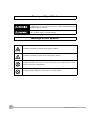
Meanings of Signal Words
The following signal words are used in this manual.
Indicates a potentially hazardous situation which, if not avoided, will result in minor
or moderate injury, or may result in serious injury or death. Additionally there may
be significant property damage.
Indicates a potentially hazardous situation which, if not avoided, may result in
minor or moderate injury or in property damage.
Meanings of Alert Symbols
The following alert symbols are used in this manual.
Indicates the possibility of explosion under specific conditions.
Indicates the possibility of electric shock under specific conditions.
Indicates prohibition when there is a risk of minor injury from electrical shock or other
source if the product is disassembled.
Indicates general prohibitions for which there is no specific symbol.
4
ZR-RX70 User’s Manual
Alert Statements in this Manual
The following alert statements apply to the products in this manual. Each alert statement also appears at the
locations needed in this manual to attract your attention.
This product cannot be used for directly or indirectly detecting human bodies to ensure
safety.
Do not use this product as a human body protection device.
Serious hazard may occur in rare occasions due to ignition, rupture or combustion of
the lithium battery contained in this product.
Never disassemble, deform under pressure, heat or incinerate this product.
Serious hazard may occur in rare occasions due to ignition, rupture or combustion.
Never disassemble, deform under pressure, heat or incinerate the lithium ion battery
pack ZR-XRB1 (GRAPHTEC:B-517).
Hazard may occur from serious fire or electric shock.
Do not connect voltages exceeding the rated voltage to the signal input terminals.
Fire or hazard may occur in rare occasions from ignition, rupture or combustion.
Do not use battery packs other than ZR-XRB1.
Hazard may occur from electric shock.
Do not remove the protection cap for unused BNC terminal. Be sure to leave the cap
(supplied) attached to this terminal.
Hazard may occur from electric shock.
Be sure to connect the terminal of this product to the cable first, and connect the
measurement object.
Injuries from electric shock may occur in rare occasions as the result of disassembly.
Never disassemble, deform under pressure or incinerate the main unit.
ZR-RX70 User’s Manual
5
Precautions for Safe Use
Be sure to observe the following items as they are very important to ensure safety.
1.Installation environment
•
•
•
•
Do not store or use in locations where the temperature exceeds the rated range.
Do not use in locations where the relative humidity exceeds the 30 to 80 %RH range.
Do not use in locations subject to steam.
Do not use in flammable or explodable gas environment.
2.Installation category
• The ZR-RX70 conforms to the IEC60664-1 installation category II, and must not be used under the
environment of the installation category III and IV.
3.Measurement category
• The ZR-RX70 is classified as measurement category I defined by IEC61010-1, and must not be used within
measurement category II, III and IV.
4.Power supply and wiring
•
•
•
•
•
•
•
•
•
Do not connect voltages exceeding the rated voltage to signal cables.
Be sure to check the polarity of the signals when connecting the signal cables.
When using the battery pack, be sure to read the cautions on the battery pack carefully for correct usage.
Be sure to use only the specified battery pack.
Be sure to use only the AC cable and the AC adapter provided as standard accessories.
Do not connect power supplies exceeding the rated voltage to the AC adapter.
Be sure to turn off the power supply when connecting to the input terminals.
Do not touch the input terminals during measurement.
Do not input signals to the M3 screw type terminal and the BNC connector of the same channel at the same
time.
5.Others
• Dispose of this product as industrial waste.
• If there are any troubles, stop usage immediately, turn off the power supply and contact OMRON branch or
sales office.
6
ZR-RX70 User’s Manual
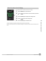
Precautions for Correct Use
Please observe the following precautions to prevent inoperability, misoperation of the product or negative
effects on the performance and the device.
1.Installation Location
Do not install this product in the following locations.
•
•
•
•
•
•
•
•
Locations where the temperature exceeds the rated range
Locations where severe changes in temperature occur (where condensation occurs)
Locations subject to corrosive or flammable gases
Locations subject to dust, salt or iron powder
Locations subject to direct shock or vibration
Locations subject to direct sunlight or near heating devices
Locations where water, oil or chemical products may be splashed
Locations subject to strong magnetic fields or strong electric fields
2.Power supply, connecting and wiring
• The cables should be wired apart from high-tension or power lines.
Malfunction or damage may occur due to induction.
• After wiring, check the adequacy of power supply voltage, miswiring such as overvoltage/load shortcircuiting and adequacy of load current before turning on the power supply.
Malfunction may occur due to miswiring and such.
• Always turn off the power supply when attaching or removing peripheral devices.
Attaching or removing of peripheral devices with the power supply on can cause malfunction or data
corruption.
3.Installation
• Do not cover the vent hole when using this product.
Leave at least 30cm of installation space around this product.
The generated heat may cause malfunction or damage.
• When measuring temperature, install the product so that the input terminals are not subject to severe
changes in temperature by wind or sunlight.
It may cause calculation errors.
• Connect the GND terminal for safe measurement. This product must also be grounded when sharing a
common ground level with other devices.
4.Warm up
• For stable measurement, wait at least 30 minutes after turning on the power supply before using.
5.Handling
• Be sure to take backups of captured data in your PC. The captured content may be altered or lost due to
misuse or malfunctions during usage.
• Do not drop or apply strong impact or force to the product.
It may cause malfunction of the monitor or the main unit.
6.Maintenance
• Do not use thinner, benzine, acetone or kerosene to clean this product.
• Calibration should be performed periodically to maintain measurement accuracy.
ZR-RX70 User’s Manual
7
Checking the Accessories
Item
Remarks
Quantity
Standard Set
ZR-RX70A
Main unit
AC adapter/AC cable
User’s Manual (this manual)
Utility disk (CD-ROM)
1
1
1
1
•
•
•
•
•
8
Specal PC software “Wave Inspire RX“ (tryout)
Basic PC software “Smart Viewer RX70”
User's Manual PDF files (this manual)
“Wave Inspire RX“ Software Manual PDF files
“Smart Viewer RX70” Software Manual PDF files
ZR-RX70 User’s Manual
Editor’s Note
Meaning of Symbols
Menu items that are displayed on the ZR-RX70’s LCD screen, and windows, dialog boxes and other GUI
elements displayed on the PC are indicated enclosed by double quotes “ ”.
Visual Aids
Important
Note
Indicates points that are important to achieve the full product performance, such as operational
precautions.
Indicates application procedures.
Indicates pages where related information can be found.
ZR-RX70 User’s Manual
9
MEMO
10
ZR-RX70 User’s Manual
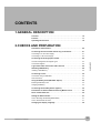
CONTENTS
1.GENERAL DESCRIPTION
Overview . . . . . . . . . . . . . . . . . . . . . . . . . . . . . . . . . . . . . . . . . . . . . . . . . . . 16
Features . . . . . . . . . . . . . . . . . . . . . . . . . . . . . . . . . . . . . . . . . . . . . . . . . . . . 17
Operating Environment . . . . . . . . . . . . . . . . . . . . . . . . . . . . . . . . . . . . . . . 18
2.CHECKS AND PREPARATION
Part Names and Functions . . . . . . . . . . . . . . . . . . . . . . . . . . . . . . . . . . . . . 20
Connecting the Power Cable and Turning on the Power . . . . . . . . . . . . 21
Connecting to an AC Power Supply. . . . . . . . . . . . . . . . . . . . . . . . . . . . . . . . . . . 21
Connecting to a DC Power Supply . . . . . . . . . . . . . . . . . . . . . . . . . . . . . . . . . . . 23
Connecting the Analog Input Terminal . . . . . . . . . . . . . . . . . . . . . . . . . . . 24
Terminal Configuration and Signal Types . . . . . . . . . . . . . . . . . . . . . . . . . . . . . . 24
CONTENTS
Connection Diagram . . . . . . . . . . . . . . . . . . . . . . . . . . . . . . . . . . . . . . . . . . . . . . 25
Logic Alarm Cable Connection and Functions . . . . . . . . . . . . . . . . . . . . 26
Attaching USB Memory . . . . . . . . . . . . . . . . . . . . . . . . . . . . . . . . . . . . . . . 29
Inserting a USB Memory . . . . . . . . . . . . . . . . . . . . . . . . . . . . . . . . . . . . . . . . . . . 29
Connecting to a PC . . . . . . . . . . . . . . . . . . . . . . . . . . . . . . . . . . . . . . . . . . . 30
Connection Using a USB Cable. . . . . . . . . . . . . . . . . . . . . . . . . . . . . . . . . . . . . . 30
LAN Connection. . . . . . . . . . . . . . . . . . . . . . . . . . . . . . . . . . . . . . . . . . . . . . . . . . 31
Using the Battery Pack (ZR-XRB1: Option) . . . . . . . . . . . . . . . . . . . . . . . 32
Mounting the Battery Pack. . . . . . . . . . . . . . . . . . . . . . . . . . . . . . . . . . . . . . . . . . 32
Charging the Battery . . . . . . . . . . . . . . . . . . . . . . . . . . . . . . . . . . . . . . . . . . . . . . 33
Connecting the Humidity Sensor (Option) . . . . . . . . . . . . . . . . . . . . . . . . 34
Precautions to Observe When Performing Measurement. . . . . . . . . . . . 35
Noise Countermeasures . . . . . . . . . . . . . . . . . . . . . . . . . . . . . . . . . . . . . . . 36
Setting the Date and Time . . . . . . . . . . . . . . . . . . . . . . . . . . . . . . . . . . . . . 37
How to Recharge the Rechargeable Battery . . . . . . . . . . . . . . . . . . . . . . . . . . . . 37
How to Set the Date and Time. . . . . . . . . . . . . . . . . . . . . . . . . . . . . . . . . . . . . . . 37
Changing the Display Language . . . . . . . . . . . . . . . . . . . . . . . . . . . . . . . . 38
ZR-RX70 User’s Manual
11
3.SETTINGS AND MEASUREMENT
Window names and functions . . . . . . . . . . . . . . . . . . . . . . . . . . . . . . . . . . 40
Key Operation . . . . . . . . . . . . . . . . . . . . . . . . . . . . . . . . . . . . . . . . . . . . . . . 44
(1) CH SELECT . . . . . . . . . . . . . . . . . . . . . . . . . . . . . . . . . . . . . . . . . . . . . . . . . . 44
(2) SPAN/TRACE/POSITION . . . . . . . . . . . . . . . . . . . . . . . . . . . . . . . . . . . . . . . 45
(3) TIME/DIV . . . . . . . . . . . . . . . . . . . . . . . . . . . . . . . . . . . . . . . . . . . . . . . . . . . . 46
(4) MENU . . . . . . . . . . . . . . . . . . . . . . . . . . . . . . . . . . . . . . . . . . . . . . . . . . . . . . . 46
(5) QUIT . . . . . . . . . . . . . . . . . . . . . . . . . . . . . . . . . . . . . . . . . . . . . . . . . . . . . . . . 47
(6) Direction keys . . . . . . . . . . . . . . . . . . . . . . . . . . . . . . . . . . . . . . . . . . . . . . . . . 47
(7) ENTER . . . . . . . . . . . . . . . . . . . . . . . . . . . . . . . . . . . . . . . . . . . . . . . . . . . . . . 48
(8) FAST FORWARD keys (KEY LOCK) . . . . . . . . . . . . . . . . . . . . . . . . . . . . . . . 48
(9) START/STOP (USB Drive Mode). . . . . . . . . . . . . . . . . . . . . . . . . . . . . . . . . . 48
(10) REVIEW . . . . . . . . . . . . . . . . . . . . . . . . . . . . . . . . . . . . . . . . . . . . . . . . . . . . 49
(11) DISPLAY . . . . . . . . . . . . . . . . . . . . . . . . . . . . . . . . . . . . . . . . . . . . . . . . . . . 50
(12) CURSOR (ALARM CLEAR) . . . . . . . . . . . . . . . . . . . . . . . . . . . . . . . . . . . . . 51
(13) FILE . . . . . . . . . . . . . . . . . . . . . . . . . . . . . . . . . . . . . . . . . . . . . . . . . . . . . . . 52
(14) NAVI . . . . . . . . . . . . . . . . . . . . . . . . . . . . . . . . . . . . . . . . . . . . . . . . . . . . . . . 52
Operation Modes . . . . . . . . . . . . . . . . . . . . . . . . . . . . . . . . . . . . . . . . . . . . . 54
(1) Free Running . . . . . . . . . . . . . . . . . . . . . . . . . . . . . . . . . . . . . . . . . . . . . . . . . 54
(2) Capturing . . . . . . . . . . . . . . . . . . . . . . . . . . . . . . . . . . . . . . . . . . . . . . . . . . . . 55
(3) Capturing and Replaying . . . . . . . . . . . . . . . . . . . . . . . . . . . . . . . . . . . . . . . . 55
(4) Replaying . . . . . . . . . . . . . . . . . . . . . . . . . . . . . . . . . . . . . . . . . . . . . . . . . . . . 56
Setting Menus . . . . . . . . . . . . . . . . . . . . . . . . . . . . . . . . . . . . . . . . . . . . . . . 57
(1) AMP Settings . . . . . . . . . . . . . . . . . . . . . . . . . . . . . . . . . . . . . . . . . . . . . . . . . 57
(2) DATA Settings . . . . . . . . . . . . . . . . . . . . . . . . . . . . . . . . . . . . . . . . . . . . . . . . 63
(3) TRIG Settings . . . . . . . . . . . . . . . . . . . . . . . . . . . . . . . . . . . . . . . . . . . . . . . . . 69
(4) OPT Settings . . . . . . . . . . . . . . . . . . . . . . . . . . . . . . . . . . . . . . . . . . . . . . . . . 75
(5) OTHR Settings . . . . . . . . . . . . . . . . . . . . . . . . . . . . . . . . . . . . . . . . . . . . . . . . 77
(6) FILE Menu . . . . . . . . . . . . . . . . . . . . . . . . . . . . . . . . . . . . . . . . . . . . . . . . . . . 80
(7) File Box. . . . . . . . . . . . . . . . . . . . . . . . . . . . . . . . . . . . . . . . . . . . . . . . . . . . . . 85
(8) Text Input . . . . . . . . . . . . . . . . . . . . . . . . . . . . . . . . . . . . . . . . . . . . . . . . . . . . 88
(9) Data Replay Menu . . . . . . . . . . . . . . . . . . . . . . . . . . . . . . . . . . . . . . . . . . . . . 89
(10) NAVI Menu . . . . . . . . . . . . . . . . . . . . . . . . . . . . . . . . . . . . . . . . . . . . . . . . . . 93
(11) Quick Settings . . . . . . . . . . . . . . . . . . . . . . . . . . . . . . . . . . . . . . . . . . . . . . . 93
(12) Canceling Key Lock with Password . . . . . . . . . . . . . . . . . . . . . . . . . . . . . . . 94
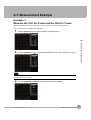
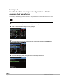
X-Y Measurement Example . . . . . . . . . . . . . . . . . . . . . . . . . . . . . . . . . . . . 95
Example 1:
Measure the CH1 for X-axis and the CH2 for Y-axis. . . . . . . . . . . . . . . . . . . . . . 95
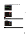
Example 2:
Overlay the data on the previously captured data to compare their waveforms. . 98
WEB Server Function . . . . . . . . . . . . . . . . . . . . . . . . . . . . . . . . . . . . . . . . 100
12
ZR-RX70 User’s Manual
4.SPECIFICATIONS
Standard Specifications . . . . . . . . . . . . . . . . . . . . . . . . . . . . . . . . . . . . . . 108
Standard Specifications . . . . . . . . . . . . . . . . . . . . . . . . . . . . . . . . . . . . . . . . . . . 108
Analog Input Measurement Accuracy . . . . . . . . . . . . . . . . . . . . . . . . . . . . . . . . 110
Main Functions. . . . . . . . . . . . . . . . . . . . . . . . . . . . . . . . . . . . . . . . . . . . . . . . . . 111
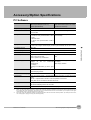
Accessory/Option Specifications . . . . . . . . . . . . . . . . . . . . . . . . . . . . . . 113
PC Software. . . . . . . . . . . . . . . . . . . . . . . . . . . . . . . . . . . . . . . . . . . . . . . . . . . . 113
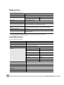
Battery Pack. . . . . . . . . . . . . . . . . . . . . . . . . . . . . . . . . . . . . . . . . . . . . . . . . . . . 114
Humidity Sensor. . . . . . . . . . . . . . . . . . . . . . . . . . . . . . . . . . . . . . . . . . . . . . . . . 114
External Dimensions. . . . . . . . . . . . . . . . . . . . . . . . . . . . . . . . . . . . . . . . . 115
5.APPENDIX
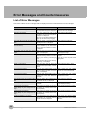
Error Messages and Countermeasures . . . . . . . . . . . . . . . . . . . . . . . . . 118
List of Error Messages . . . . . . . . . . . . . . . . . . . . . . . . . . . . . . . . . . . . . . . . . . . . 118
List of File Error Messages . . . . . . . . . . . . . . . . . . . . . . . . . . . . . . . . . . . . . . . . 119
Index . . . . . . . . . . . . . . . . . . . . . . . . . . . . . . . . . . . . . . . . . . . . . . . . . . . . . . 121
Revision History . . . . . . . . . . . . . . . . . . . . . . . . . . . . . . . . . . . . . . . . . . . . 124
CONTENTS
ZR-RX70 User’s Manual
13
14
ZR-RX70 User’s Manual
1
GENERAL DESCRIPTION
GENERAL DESCRIPTION
This chapter provides a general description of the ZR-RX70 and its
features.
Overview
16
Features
17
Operating Environment
18
Overview
The ZR-RX70 (with color monitor and internal memory) are compact, lightweight, 8 channel data loggers.
ZR-RX70 are also equipped with an internal flash memory to store data and enable the direct capture of a large
volume of data to USB memory.
Furthermore, the data loggers are equipped with USB and Ethernet interfaces to a PC to enable system
configurations according to your application.
The Ethernet feature includes WEB and FTP server and NTP client functions which allow monitoring from a
remote location, data transfer, and automatic time synchronization.
16
Overview
ZR-RX70 User’s Manual
Features
Input
• The input terminals come in two types: easy-to-connect BNC connectors and M3 screw type terminals, which facilitate wiring of thermocouples.
1
• All channels are isolated, enabling measurement of signals of different references.
Display & Operation
GENERAL DESCRIPTION
• With the ZR-RX70’s 5.7-inch TFT color liquid crystal display, you can confirm the waveforms of measured data and
each channel’s settings at a glance.
• Easy operation is achieved through a straightforward menu structure and key allocation which resembles mobile
phones.
• The relationships between timers and triggers are displayed graphically in an easy-to-understand manner.
Data Capture
• Data can be saved to the internal flash memory or external USB memory. The saved data will be retained even after
the power is turned off.
• The internal flash memory can be used with disk images thus multiple data items can be maintained.
• Setting the data capture destination to the internal RAM enables quick capture of data. After checking the captured
data, you can save it to the internal flash memory or USB memory if required.
Data Control & Processing
• The PC software provided lets you set conditions and monitor data on a PC.
• The USB drive mode function enables the ZR-RX70’s internal flash memory to be recognized as an external drive
by your PC. (Connect the ZR-RX70 to your PC and turn on the power supply to the ZR-RX70 while holding down
the [START] key.)
• Captured data can be read from the PC software to files and displayed for processing.
• Data can be transferred off-line to a computer using USB memory.
• The WEB server function enables control and monitoring from a remote location without using dedicated software.
• The FTP server function enables handling internal memory and USB memory data from a PC.
• The NTP client function enables adjusting the time according to the NTP server.
ZR-RX70 User’s Manual
Features
17
Operating Environment
This section explains the operating environment for the ZR-RX70.
See “Precautions for Safe Use” p. 6
See “Precautions for Correct Use” p. 7
Note
Condensation occurs in the form of water droplets on the device surfaces and interior when the ZR-RX70 is moved
from a cold to a warm location. Using the ZR-RX70 with condensation will cause malfunctioning. Wait until the condensation has disappeared before turning on the power.
Warming-up Before Use
The ZR-RX70 should be allowed to warm up with the power turned on for approximately 30 minutes to ensure
that it operates according to the specified performance.
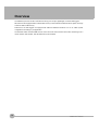
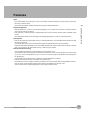
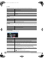
Configuration When in Use
Use the ZR-RX70 standing upright or at an angle, being set on the stand.
90 degrees
Standing upright
Standing at an angle, being set on the stands
How to open the stands
Important
Do not block the air vent on the ZR-RX70, as this will cause malfunctioning. Measurement accuracy may not be satisfactory if the system is used in a condition other than described above.
Use both the stands of the ZR-RX70 when you use it at an angle. Otherwise, the unit will fall down. Open both the
stands before use as shown in this figure.
18
Operating Environment
ZR-RX70 User’s Manual
CHECKS AND PREPARATION
2
Part Names and Functions
20
Connecting the Power Cable and Turning on the Power 21
Connecting the Analog Input Terminal
24
Logic Alarm Cable Connection and Functions
26
Attaching USB Memory
29
Connecting to a PC
30
Using the Battery Pack (ZR-XRB1: Option)
32
Connecting the Humidity Sensor (Option)
34
Precautions to Observe When Performing Measurement
35
Noise Countermeasures
36
Setting the Date and Time
37
Changing the Display Language
38
CHECKS AND PREPARATION
This chapter explains how to check the ZR-RX70’s external casing
and accessories, and how to prepare the ZR-RX70 for operation.
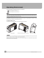
Part Names and Functions
This section describes the names and function of parts of the ZR-RX70.
PC interface terminals
Fan
Monitor
Operation status LED
• USB
• LAN
Power switch
• POWER : ON when the power is ON
• START : ON during data capture
• CHARGE : ON while the battery is charging
Fan
Control panel keys
Analog signal input BNC connector
GND terminal
USB memory terminal
AC adapter jack
Power jack for
humidity sensor
External input/output terminal
• LOGIC/PULSE : LOGIC/PULSE input
• EXT TRIG
: Trigger input
• ALARM
: Alarm output
Analog signal input terminals
Battery cover
Contains battery packs
(ZR-XRB1: Option) sold separatel.
Stands
Before using the stands, read the precautions provided in “Operating Environment”
See p.18.
20
Part Names and Functions
ZR-RX70 User’s Manual
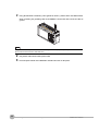
Connecting the Power Cable and Turning on the Power
This section describes how to connect the power cable and turn on the power. The connection method will vary
depending on the type of power supply used.
Connecting to an AC Power Supply
Use the AC cable and AC adapter that are provided as accessories.
Important
2
1
CHECKS AND PREPARATION
Be sure to use the AC cable and the AC adapter that are supplied as standard accessories.Connect the GND terminal
for safe measurement. The ZR-RX70 must also be grounded when sharing a common ground level with other
devices.
Plug the AC cable into the AC adapter.
AC adapter
AC cable
2
Connect the output side of the AC adapter to the AC adapter jack on the ZR-RX70.
AC adapter cable
ZR-RX70 User’s Manual
Connecting the Power Cable and Turning on the Power
21
3
Using the flat-blade screwdriver, press against the minus (–) button above the GND terminal,
while connecting the grounding cable to the ZR-RX70. Connect the other end of the cable to
ground.
Note
The ground cable is not provided as a standard accessory and must be prepared separately.
[Recommended Cord Diameter: AWG18/UL1007]
22
4
Plug the AC cable into the mains power outlet.
5
Press the power switch on the ZR-RX70 to the ON side to turn on the power.
Connecting the Power Cable and Turning on the Power
ZR-RX70 User’s Manual
Connecting to a DC Power Supply
Use the optional DC cable (ZR-XRD1: option).
Important
• Be sure to use the separately sold DC cable (ZR-XRD1).
• Do not apply voltages exceeding the rated voltage (8.5 to 24 VDC).
• Connect the GND terminal for safe measurement. The ZR-RX70 must also be grounded when sharing a common
ground level with other devices.
• Be sure to check the polarity of the power supply when connecting the DC cable.
Configure the tip of the DC cable (ZR-XRD1: option, 2m) to enable it to be connected to the DC
2
1
power supply.
CHECKS AND PREPARATION
2
Connect the DC cable connector to the power supply connector on the ZR-RX70.
Shielded lead (- side)
White (+ side)
DC cable
(ZR-XRD1: option)
3
Using the flat-blade screwdriver, press against the minus (–) button above the GND terminal, while
connecting the grounding cable to the ZR-RX70. Connect the other end of the cable to ground.
4
Connect the DC cable to the DC power supply.
5
Press the power switch on the ZR-RX70 to the ON side to turn on the power.
ZR-RX70 User’s Manual
Connecting the Power Cable and Turning on the Power
23
Connecting the Analog Input Terminal
This section describes how to connect the analog input terminal.
Terminal Configuration and Signal Types
Important
• Do not input signals to the screw type terminal and the BNC
BNC connector
connector of the same channel at the same time.
Screw type
terminals
Doing so may cause damage to the connected device.
• Make sure that the signal input source is OFF before con-
ZR-RX70
necting the cables in order to prevent electric shocks.
When applying voltage of 60V or above, use available safety cable in order to prevent electric shocks.
• Set the input range for the voltage to measure before you connect the analog input terminal. The maximum input
voltage for the 20 mV to 1 V range is ±30 VDC. If you apply a higher voltage without changing the input range, the
data logger may be damaged.
CH8 . . . . . . . . . . . . . . . . . . . . . . . . . . . . . . . . . . . . . . . . . . . . CH1
High-voltage teriminal
Low-voltage teriminal
Screw type terminal
BNC connector
The screw type terminal and the BNC connector are internally connected. Data entered
to either of them can be measured.
Note
If you use plobe, use one with attenuation rate 1/1.
24
Connecting the Analog Input Terminal
ZR-RX70 User’s Manual
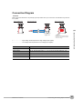
Connection Diagram
Important
Make sure that the ZR-RX70 is not pulled by signal input cables when you connect them. The ZR-RX70 may fall down
if it is pulled.
Direct voltage input
Thermocouple input
Direct current input
2
CHECKS AND PREPARATION
Compensation
copper wire
Direct voltage
Direct current
Shunt resistor
Example: If 4-20 mA is used, connect
a 250 Ω (±0.1%) resistor and measure
it in the 1-5 V range.
+........................... High-voltage terminal (terminal for high-voltage input signals)
– ........................... Low-voltage terminal (terminal for low-voltage input signals)
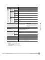
Item
Description
Input configuration
Isolated input, scanning
Analog voltage
20, 50, 100, 200, 500 mV/F.S.; 1, 2, 5, 10, 20, 50, 100, 200, 500V/F.S.; 1-5V
Thermocouples
K, J, E, T, R, S, B, N, W (WRe 5-26)
A/D resolution
16-bit
Filter
Off, Line, 5, 50, 500Hz
ZR-RX70 User’s Manual
Connecting the Analog Input Terminal
25
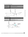
Logic Alarm Cable Connection and Functions
The logic alarm cable (ZR-XRL1: option) enables logic/pulse input, external trigger/sampling input, and alarm
signal output.
Connect the logic alarm cable (ZR-XRL1: option) to the external input/output terminal as shown below.
Logic alarm cable (ZR-XRL1: option)
Logic/Pulse Specifications
Item
Description
Number of input channels
4
Input voltage range
0 to +24V max. (single-ended ground input)
Threshold level
Approx. +2.5V
Hysteresis
Approx. 0.5 V (+2.5 to +3 V)
Note
Switch between logic and pulse input.
Internal Equivalence Circuit
26
Logic Alarm Cable Connection and Functions
ZR-RX70 User’s Manual
External trigger/sampling Specifications
Item
Description
Number of input channels
1
Input voltage range
0 to +24V max. (single-ended ground input)
Threshold level
Approx. +2.5V
Hysteresis
Approx. 0.5 V (+2.5 to +3 V)
Internal Equivalence Circuit
2
CHECKS AND PREPARATION
Alarm Output Specifications
Item
Description
Number of input channels
4
Output format
Open collector output
+5 V, 10 KΩ pull-up resistance
Contact capacity 5 V to 24 V, 100 mA or below
Internal Equivalence Circuit and Example of Wiring Connection
ZR-RX70 User’s Manual
Logic Alarm Cable Connection and Functions
27
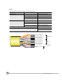
Wiring
Cable tips are bare tips. Perform wiring for the necessary functions.
Signal Name
Channel Number
Wire Color
Logic/Pulse input
1
Orange with red dotted line
2
Orange with black dotted line
3
Grey with red dotted line
4
Grey with black dotted line
1
White with red dotted line
2
White with black dotted line
3
Yellow with red dotted line
4
Yellow with black dotted line
Alarm output
External trigger/sampling input
Pink with red dotted line
GND
Pink with black dotted line
Shielded
* Switch between logic and pulse.
Orange with red dotted line
:1
Orange with black dotted line
:2
Grey with red dotted line
:3
Grey with black dotted line
:4
White with red dotted line
:1
White with black dotted line
:2
Yellow with red dotted line
:3
Yellow with black dotted line
:4
Pink with red dotted line
: External trigger/
sampling input
Pink with black dotted line
Shielded
28
Logic Alarm Cable Connection and Functions
Logic/Pulse input
Alarm output
GND
ZR-RX70 User’s Manual
Attaching USB Memory
Attaching USB memory to the ZR-RX70 allows you store measured data directly.
Important
<Specifications of supported USB memory>
• Power source
: +5 V
• Power consumption
: 250 mA or below
• Capacity
: No limit (except each file must be within 2 GB)
2
CHECKS AND PREPARATION
You cannot use USB memory with a security function such as fingerprint authentication or with no shell
(metallic part) in the connector area.
Inserting a USB Memory
Attach the USB memory to the USB memory terminal.
USB memory
ZR-RX70 User’s Manual
Attaching USB Memory
29
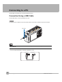
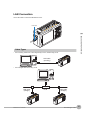
Connecting to a PC
Use the USB, LAN Interface to connect the ZR-RX70 to a PC.
Connection Using a USB Cable
Use the USB cable to connect the ZR-RX70 to a PC.
Important
The USB connector is adjacent to the LAN connector. Make sure the cable is inserted into the correct connector.
USB cable
Note
If the USB cable is used, the USB driver must be installed in your PC. Refer to “Installing the USB Driver” in the “PC
Software Manual”.
• Use an A-B type USB cable to connect the ZR-RX70 to a PC
A connector
30
Connecting to a PC
B connector
ZR-RX70 User’s Manual
LAN Connection
Use a LAN cable to connect the ZR-RX70 to a PC.
LAN cable
2
CHECKS AND PREPARATION
Cable Types
• Use a crossing cable when connecting directly to a PC, without using a hub.
LAN cable
(crossing)
• Use a straight cable when using a hub.
LAN cable
(straight)
ZR-RX70 User’s Manual
HUB
LAN cable
(straight)
Connecting to a PC
31
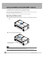
Using the Battery Pack (ZR-XRB1: Option)
The ZR-XRB1 (option) is the only battery type that can be used with the ZR-RX70.
Two battery packs need to be mounted when you have the ZR-RX70 run on batteries.
You can also mount only one battery pack when you charge it (using the AC power source). At this time, the
battery pack can be mounted on either the right or left.
The running time using batteries is about 2.5 hours when the screen saver is operating.
Mounting the Battery Pack
1
While lightly pushing the grip of the battery cover, slid the cover in the direction indicated by the
arrow.
1
2
2
Attach the battery pack (ZR-XRB1: option).
2
1
Attach the battery with care of polarity
and insertion direction.
Note
When you have the ZR-RX70 run on batteries, be sure to mount two battery packs with the same charge level.
Do not use the battery packs with the different charge level at the same time.
If you are not sure about the amount, charge each battery and then attach full-charged two battery packs.
32
Using the Battery Pack (ZR-XRB1: Option)
ZR-RX70 User’s Manual
3
Attach the battery cover.
2
CHECKS AND PREPARATION
Charging the Battery
You can mount either one or two battery packs when you charge them.
Note
Expected time required for charging:
• battery pack x 1: approx. 4 hours
• battery pack x 2: approx. 8 hours
The battery pack is charged by mounting it in the ZR-RX70, attaching AC adapter to the ZR-RX70.
1
2
Mount the battery pack in the ZR-RX70 (See the previous section for the mounting procedure).
Turn on the power to the ZR-RX70.
See “Connecting the Power Cable and Turning on the Power” p. 21.
3
The CHARGE LED lights.
CHARGE LED
Note
• ZR-RX70 is equipped with a temperature monitor function which starts automatic charging as soon as it is cooled
down. Therefore, depending on the internal temperature, charging may not be performed immediately.
When charging is attempted while the power is ON, charging may not be performed immediately depending on
the temperature environment.
In such a case, set the Screen Saver settings to ON. ZR-RX70 will start charging as soon as it is cooled down.
Charging temperature: 15 to 35 °C
• If input is being made directly from the DC power supply instead of the AC adapter, the DC voltage must be at
least approx. 16 V.
ZR-RX70 User’s Manual
Using the Battery Pack (ZR-XRB1: Option)
33
Connecting the Humidity Sensor (Option)
Connect the + and – lead wires of the humidity sensor (the ZR-XRH1 option) to the desired terminals, and then
insert the round connector into the 5V OUT connector on the ZR-RX70.
Important
Do not use the sensor in a strong electrolyte environment. Measured results may not satisfy to the stated.
Humidity sensor
(ZR-XRH1: option)
Connect to the
5V OUT terminal
Brown
White
Humidity sensor
34
Connecting the Humidity Sensor (Option)
ZR-RX70 User’s Manual
Precautions to Observe When Performing Measurement
Please be sure to read the following carefully in order to prevent electric shocks or shorts.
Important
• Do not apply voltage of 60 Vp-p or above between the analog input-terminal and main unit (GND terminal), or
between analog input-terminals.
• Be sure to use only the AC adapter provided as a standard accessory. The rated power supply range for the
adapter is 100 to 240 VAC, and the rated frequency is 50/60 Hz. Do not use any other voltages.
2
For details, see “Connection Diagram” p. 25.
CHECKS AND PREPARATION
ZR-RX70 User’s Manual
Precautions to Observe When Performing Measurement
35
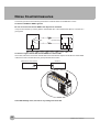
Noise Countermeasures
Connect the ground wire in the following method if the measured values are unstable due to noise.
Connect the ZR-RX70's GND to ground.
Be sure to connect the chassis GND of the object to be measured.
It may become effective by ensuring that the chassis GND wire of the measurement object is connected to a
good ground.
Measurement object
Thermocouple
ZR-RX70
R1
+
Input terminals
Vin
–
R2
Z3
Z1
Z2
Connect the signal chassis GND and the ZR-RX70’s chassis GND.
Use a short, thick lead to connect the chassis GND of the measurement object to the ZR-RX70’s chassis GND.
It will become even more effective if the ground potentials are the same.
Measurement device chassis
GND
ZR-RX70
GND
In the AMP Settings menu, set Filter to any setting other than OFF.
36
Noise Countermeasures
ZR-RX70 User’s Manual
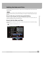
Setting the Date and Time
If you are using the ZR-RX70 for the first time, charge the internal rechargeable battery and then make the date
and time settings.
Important
If the ZR-RX70 is not used for a period of approximately six months, the internal rechargeable battery may be discharged and the date and time may revert to the initial settings. If this happens, recharge the battery before using the
ZR-RX70.
2
How to Recharge the Rechargeable Battery
CHECKS AND PREPARATION
Using the AC adapter provided, connect the ZR-RX70 to a mains power outlet, turn on the power switch, and
then leave the ZR-RX70 connected for at least 24 hours.
How to Set the Date and Time
Press the [MENU] key, display the “OTHR” screen, and then set the date and time at the Date/Time Settings
sub-menu.
For details, see “(5)-8 Date/Time” p. 78.
ZR-RX70 User’s Manual
Setting the Date and Time
37
Changing the Display Language
You can choose the language displayed on the screen. The default display language is set to English when the
ZR-RX70 is shipped overseas.
ZR-RX70A: Japanese
ZR-RX70A-E,-U,-B,-CHRO: English
To change the display language, see the instructions in "OTHR:Language".
38
Changing the Display Language
ZR-RX70 User’s Manual
SETTINGS AND MEASUREMENT
3
Window names and functions
40
Key Operation
44
Operation Modes
54
Setting Menus
57
X-Y Measurement Example
95
WEB Server Function
100
SETTINGS AND MEASUREMENT
This chapter describes the setting and measurement procedures for
the ZR-RX70.
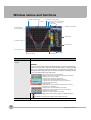
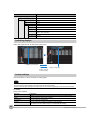
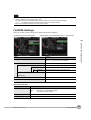
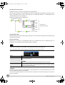
Window names and functions
1. Simplified message display
2. Time/DIV
3. USB memory access display
4. Internal flash memory access display
5. Key lock lamp
7. Clock lamp
6. Remote lamp
8. AC/Battery status display
17. Data capture bar
16. Scale upper limit
9. Digital display
15. Waveform display
10. Quick settings
14. Scale lower limit
11. Alarm display
12. Pen display
13. File name display
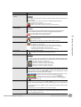
Item
Description
1. Simplified message
display
Displays the system operation status.
Important
Do not turn off the power while the simplified message is “Capturing and Replaying”,
“Capturing to Internal RAM”, “Capturing to Internal Flash Memory”, “Capturing to USB
Memory”, or “Auto Saving” (those with an asterisk (*) in the list below). Otherwise, the
captured data will be destroyed. Make sure that the message is completely gone (wait
for 2 or 3 seconds) before turning off the power.
: Startup status or data is not being captured
: Waiting for generation of a trigger after measurement has started
: Waiting for the time set on the timer
: Capturing data and replaying captured data
: Capturing data to the internal RAM of the ZR-RX70
: Capturing data to the internal flash memory of the ZR-RX70
: Capturing data to USB memory
: Auto-saving data
(Data captured in the internal RAM is being saved to the internal
flash memory or USB memory.)
: Replaying data in the internal RAM of the ZR-RX70
: Replaying data in the internal flash memory of the ZR-RX70
: Replaying data in USB memory
: Waiting for the specified repeat time to elapse
For details on data capture such as timer, trigger, and repeat, see p.69.
For details on memory to be used for data capture, see p.65.
2. Time/DIV
40
Displays the current time scale.
Window names and functions
ZR-RX70 User’s Manual
Item
3. USB memory access
display
Description
Important
Do not remove the USB memory and/or turn OFF the device while the USB memory is
being accessed.
Failure to observe this caution may result in corrupted data and data loss.
: No USB memory is inserted.
: USB memory is inserted but not being accessed.
: USB memory is being accessed. Do not remove the USB memory.
4. Internal flash memory
access display
Important
Do not turn OFF the device while the internal flash memory is being accessed.
Failure to observe this caution may result in corrupted data and data loss.
: The internal flash memory is not being accessed.
: The internal flash memory is being accessed.
3
5. Key lock display
SETTINGS AND MEASUREMENT
: The keys are not locked. Normal operation is enabled.
: All the keys are locked.
For details on memory to be used for data capture, see p.94.
6. Remote display
7. Clock display
: The ZR-RX70 is in local mode. The ZR-RX70 can be operated from itself.
: The ZR-RX70 is in remote mode.
The ZR-RX70 can be operated from a PC except for some operations.
To switch from remote mode back to local mode, clear the PC connection.
The ZR-RX70 will automatically return to local mode.
If the ZR-RX70 does not return to local mode, press the QUIT key.
Displays the current date and time.
For details on the date and time settings, see p.78.
8. AC/battery status display
Important
If the power is cut due to a power failure or a dead battery while data is being captured, the data being captured will be lost. Pay attention to the remaining battery level.
: Running on the AC or DC power source.
: Running on the battery. The battery level is high.
: Running on the battery. The battery level is middle.
: Running on the battery. The battery level is low.
: Running on the battery. The battery is nearly out.
9. Digital display
Displays the input values for each channel. The [SPAN/TRACE/POSITION] key is
and
keys or the [CH SELECT] key can be used
used to change the display. The
to select the active channel (enlarged display). Moreover, the selected active channel
is displayed at the very top of the waveform display.
: Displays the input values. The input channels to be assigned can be changed using X-Y Display.
: The span of the active channel can be changed using and keys.
: The position of the active channel can be changed using and keys.
: The display of the active channel can turned ON and OFF using and keys.
For details, see p.45.
10. Quick settings
Displays items that can be easily set. The
and
keys or the [CH SELECT] key can
be used to make a Quick settings item active and the
and
keys to change the values.
During Free Running in X-Y display, the pen can be moved up/down and the screen
can be cleared.
* During data capture, the SAMPLE item cannot be changed.
11. Alarm display
Displays the alarm output terminal status.
Turns red if an alarm is generated. For the channel that generated the alarm, the input
value in the digital display turns red.
ZR-RX70 User’s Manual
Window names and functions
41
Item
Description
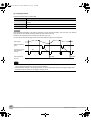
12. Pen display
Displays the signal positions, trigger positions, and alarm ranges for each channel.
Trigger position
Alarm range
Rising
Falling
Win In
Win Out
Stop position
Start position
13. File name display
Displays the data capture file name during the data capture operation. If auto save is
performed, the progress of data save is displayed with the bar in the background. Displays the data replay file name during the data replay operation.
Important
Do not turn off the power while the simplified message is “Capturing and Replaying”,
“Capturing to Internal RAM”, “Capturing to Internal Flash Memory”, “Capturing to USB
Memory”, or “Auto Saving.” Otherwise, the captured data will be destroyed. Make sure
that the message is completely gone (wait for 2 or 3 seconds) before turning off the
power.
Total size of data to be saved
Size of data that
has been saved
See also “1. Simplified message display” p. 40.
14. Scale lower limit
Displays the lower limit of the scale of the currently active channel.
15. Waveform display
Displays the waveform of the input signal.
16. Scale upper limit
Displays the upper limit of the scale of the currently active channel.
17. Data capture bar
• During data capture
Displays the elapsing time and the remaining capacity of the memory in use. The
progress of data capture is displayed with the bar in the background.
Capacity of memory available for data capture
Remaining memory
capacity available
(Remaining capacity)
Size of data that
has been captured
Elapsed time
Remaining time available
If the pre-trigger is set to other than 0% and the size of captured data
has not yet reached the level of the pre-trigger, the time remaining
until it reaches the level of the pre-trigger is displayed in yellow.
When the sampling interval is External, the number of captured samples is displayed in green.
Capacity of memory available for data capture .....
Indicates the capacity of free memory available for data capture at the start
of data capture. For example, if 128 MB of 256-MB memory is already in
use, the remaining 128 MB is displayed.
If the data capture destination is the internal RAM, the specified time available for data capture is indicated.
See p.67.
* The maximum value is 2 GB per file. 2 GB is indicated if the capacity of
free USB memory exceeds 2 GB.
Size of data that has been captured .....
Indicates how much of the above memory is currently in use for data capture.
Remaining memory capacity available .....
Indicates how much of the above memory remains available for data capture.
42
Window names and functions
ZR-RX70 User’s Manual
Item
17. Data capture bar
Description
• During Data Replay
Indicates the displayed position, cursor position, and trigger position.
Cursor A position
Trigger point location
Cursor B position
Total size of captured data
Current waveform display position
• Waiting for timer
Indicates the time at which the timer expires.
3
SETTINGS AND MEASUREMENT
ZR-RX70 User’s Manual
Window names and functions
43
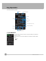
Key Operation
This section describes key operation.
1. CH SELECT
2. SPAN/TRACE/POSITION
3. TIME/DIV
5. QUIT
4. MENU
6. Direction keys
7. ENTER
8. FAST FORWARD key (KEY LOCK)
9. START/STOP (USB DRIVE)
13. FILE
14. NAVI
11. DISPLAY
10. REVIEW
12. CURSOR(ALARM CLEAR)
(1) CH SELECT
Press this switch to select the channel to change the settings in the Waveform +
Digital or X-Y screen.
Press this switch to move the active display box in the Digital + Calculation Display
screen.
p.47
44
Key Operation
ZR-RX70 User’s Manual
(2) SPAN/TRACE/POSITION
Switches the display in the digital display.
Used to change the settings related to waveform display during Free Running (when
stopped), data capture, and data replay.
Pressing this key will switch displays as shown below.
SPAN
POSITION
3
MONITOR
TRACE
SETTINGS AND MEASUREMENT
Displays digital values
(default status)
Allows changing of the span
value (waveform amplitude)
• Channel change:
CHSELECT keys
• Amplitude range change:
keys
• Change range: 8 voltage levels
/6 temperature levels
Allows changing of the position
(waveform up/down position)
• Channel change:
CHSELECT keys
• Display scale change:
keys
• Change range: In steps of 10% of
the range
Allows turning ON/OFF of
the waveform display
• Channel change:
CHSELECT keys
• Display/Hide change:
keys
• Change range: ON/OFF
* At OFF, data is captured all the same.
* When ALL is set, setting values for CH1 is reflected on other channels.
When CH1 is OFF, ALL cannot be set.
ZR-RX70 User’s Manual
Key Operation
45
(3) TIME/DIV
Press the [TIME/DIV] key to change the time axis display range.
However, when the sampling interval is External, “External” is displayed (in the red
box) and this key is inoperative.
This key is used to change the colors of the waveforms in the X-Y screen.
p.95
(4) MENU
Open the settings window to capture data. For details on settings, see “Setting
Menus”.
p.57
46
Key Operation
ZR-RX70 User’s Manual
(5) QUIT
The key is primarily used for the following operations.
• To cancel a setting during menu configuration.
• To return to the MONITOR window when the SPAN/TRACE/POSITION window is displayed.
• To cancel remote status (in which keys are disabled) through interface control.
• To close the menu screen.
• To quit data replay.
3
SETTINGS AND MEASUREMENT
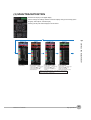
(6) Direction keys
These keys are primarily used for the following operations.
• To move in a menu or between setting items during menu configuration.
• To move the cursor during replay.
• To move the active channel in the Waveform + Digital screen or X-Y screen
(
and
keys).
• To change the setting of SPAN/TRACE/POSITION (
• To change the quick settings (
and
and
keys).
keys).
• To change the setting of the channel to be allocated in the X-Y screen (
and
keys).
• To change the number of channels displayed in the Digital + Calculation Display screen
(
and
keys).
• To change the channel displayed in the box on the Digital + Calculation Display screen
(
2-channel Display
ZR-RX70 User’s Manual
and
keys).
4-channel Display
8-channel Display
Full Channels +
Statistical Calculation
Display
Key Operation
47
(7) ENTER
This key is primarily used for the following operation:
• To finalize setting items during menu configuration or open submenus.
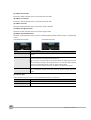
(8) FAST FORWARD keys (KEY LOCK)
These keys are primarily used for the following operation.
• To move the cursor at high speed during replay.
• To change the operation mode in the file box.
• To set key lock (Hold down the left/right FAST FORWARD keys for at least two seconds. press again to unlock)
A password for canceling the key lock can be specified.
For details, see p.94.
(9) START/STOP (USB Drive Mode)
This key is used for the following two operations:
<Starting and stopping measurement>
• Starts capture during Free Running or replay.
• Stops capture during capture.
• Press this key while turning the power ON to access USB Drive Mode.
In USB Drive Mode, the internal memory is recognized by the PC as external storage
media.
48
Key Operation
ZR-RX70 User’s Manual
<USB Drive Mode>
In USB Drive Mode, the internal memory is recognized by the PC as external storage media. With the internal
memory recognized as a removable disk, files can be easily transferred, deleted, or otherwise manipulated on
it.
1
Use a USB cable to connect the ZR-RX70 and a PC.
2
While pressing the ZR-RX70 [START/STOP] key, turn the power ON.
3
The external storage media is recognized by the PC and data exchange becomes possible.
Note
3
In USB Drive Mode, the display on the ZR-RX70 is as shown below.
SETTINGS AND MEASUREMENT
Keep pressing [START/STOP] key until the display becomes as shown below.
Important
• To cancel the USB Drive Mode, reboot the MT100.
• All operations, including data capture and replay, will be disabled during USB Drive Mode.
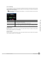
(10) REVIEW
This key is used to replay captured data.
• During Free Running, replays the last captured data.
If no data has been captured yet because it is just after the power-on, no data is
replayed (a message “No data captured” comes up).
* While capturing data, recently captured data is replayed (data capture is
continued).
ZR-RX70 User’s Manual
Key Operation
49
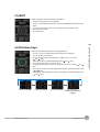
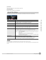
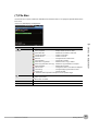
(11) DISPLAY
This key is used to switch the window mode.
You can switch the window mode during Free Running (when stopped) and
Capturing.
Pressing this key switches the window display as follows:
<Waveform + Digital Screen>
Displays waveforms and digital values.
This is the default screen when the ZR-RX70
is powered on.
The screen settings can be changed by using
the [SPAN/TRACE/POSITION] key.
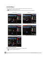
<Expanded Waveform Screen>
Displays only waveforms in a magnified view
in full screen mode.
<Digital + Calculation Display Screen>
Displays digital values and calculation results in
large text. The calculation settings can be made
using the DATA menu.
For details, see p.63.
Press the
and
keys to change the number
of channels displayed. The calculation results are
displayed only when the Full Channels + Statistical Calculation Display is selected.
For details, see p.47.
<X-Y Display Screen>
Supports four-channel X-Y display. Any given
channels can be specified for X-axis and Y-axis.
The settings can be made using the [SPAN/
TRACE/POSITION] key, the pen can be moved
up, and the screen can be cleared.
For details, see p.95.
50
Key Operation
ZR-RX70 User’s Manual
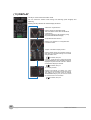
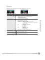
(12) CURSOR (ALARM CLEAR)
This key has different roles in different operation statuses.
<When replaying captured data>
This key is used to toggle between cursors A and B during replay.
• Waveform + Digital Screen
3
Cursor B
Cursor A
Cursor B
SETTINGS AND MEASUREMENT
Cursor A
Cursor A is in blue when selected or in gray otherwise.
Cursor B is in red when selected or in gray otherwise.
The trigger point is indicated with a green line.
• X-Y Display Screen
Cursor A
Cursor B
Cursor A
Cursor B
<When alarm generated>
When the alarm setting is “Hold generated Alarm”, the maintained alarm is cleared.
Alarm-generated channels
Alarm output terminal status
• Black : Alarm is cleared
• Red : Alarm is issued
ZR-RX70 User’s Manual
Key Operation
51
(13) FILE
• Replays data in the internal flash memory and USB memory.
• This key is used for operations related to the internal flash memory and USB memory
(such as copy and delete)
• Saves data in the internal RAM to the internal flash memory and USB memory.
• Stops the auto save process in progress.
• Overlay X-Y images in the X-Y Display screen. This is the function of displaying a
thumbnail-size image of the captured data as a background.
For details, see p.84.
• Copies the window.
• Saves the settings currently in use or loads settings.
(14) NAVI
This key is used to display the key operation content during Free Running, capture,
or replay.
During display of the NAVI screen, an explanation of how the key is used is displayed
in the window.
To exit the NAVI screen, press the NAVI key again.
52
Key Operation
ZR-RX70 User’s Manual
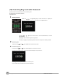
Basic Procedures Used in Settings
The following are basic operation procedures for settings.
1
Press the [MENU] key to open each menu.
2
Use the
key to move the cursor to the items you want to
set.
3
Press the [ENTER] key to display a list of setting values.
4
Use the
5
Press the [ENTER] key to confirm the value.
key to select a setting value.
3
SETTINGS AND MEASUREMENT
The above operation is the basic procedure that may be used for each setting.
However, precise procedure may vary between setting items. Please follow the procedure indicated by each
menu.
ZR-RX70 User’s Manual
Key Operation
53
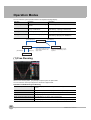
Operation Modes
You can check the system operation status in the simplified message display.
Operation
Operation
Operation
Free Running
Start up status or data is not being
captured
Free Running
Capturing
Data is being captured in the main
memory or USB device.
Capturing to Internal RAM, Capturing to Internal
Flash Memory, Capturing to USB memory
Capturing and Replaying Data being captured is being replayed Capturing and Replaying
Replaying
Captured data is being replayed
Replaying from Internal RAM, Replaying from Internal
Flash Memory, Replaying from USB Memory
Operation status transition
[START/STOP] key
Capturing
[REVIEW] key
[QUIT] key
Free Running
[REVIEW] key
[START/STOP] key
When capture ends, the screen
automatically switches to the
replay screen.
Replaying
* Data cannot be replayed just after
power-on or no data has yet been
captured.
Capturing and Replaying
(1) Free Running
When in Free Running status, you primarily set up the system to capture data.
You can check the current input signal as a waveform or digital values.
Operations available during Free Running
Measurement parameters settings
The [MENU] key is used to change various setting items in configuration
menus.
SPAN/TRACE/POSITION
The [SPAN/TRACE/POSITION] key is used to change settings.
Display mode
The [DISPLAY] key is used to change the display mode.
File operations
The [FILE] key is used to perform file-related operations.
Replay of last data (captured last time) The [REVIEW] key is used to replay captured data.
Data replay
54
Operation Modes
The [FILE] key is used to select data that you want to replay and replay it.
ZR-RX70 User’s Manual
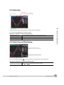
(2) Capturing
Time of Capturing
Capture time
Note: “+++++:++:++” is displayed
when the capture time is long.
3
Capture file name
SETTINGS AND MEASUREMENT
During data capture, data is captured into the Internal memory or USB device.
You cannot use the [MENU] key to change the setting.
Operations available for change during capturing
SPAN/TRACE/POSITION
The [SPAN/TRACE/POSITION] key is used to change settings.
Display mode
The [DISPLAY] key is used to change the display mode.
Capturing and Replayling
The [REVIEW] key is used to replay captured data at the same time.
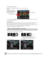
(3) Capturing and Replaying
This area displays voltages, etc. of points
indicated by Cursor A or B or the selected cursor.
This area displays measuring time, etc. of points
indicated by Cursor A or B or the selected cursor.
You can replay data during capture.
You can use the Direction keys (
) to move the cursor to captured data to check digital values.
Operations available during Capturing and Replaying
Moving cursor
ZR-RX70 User’s Manual
The [CURSOR] key is used to switch between cursors A and B.
The
or
keys are used to move the cursors.
Operation Modes
55
(4) Replaying
This area displays voltages, etc. of points
indicated by Cursor A or B or the selected cursor.
This area displays measuring time, etc. of points
indicated by Cursor A or B or the selected cursor.
When the sampling interval is External, the start
time of one data capture process and the number
of sample points are displayed.
Displays captured data.
Available operation during replaying
56
SPAN/TRACE/POSITION
The [SPAN/TRACE/POSITION] key is used to change settings.
Menu operations during data
replay
The [MENU] key is used to move the cursor, search data and replay set calculation.
Moving cursors
The [CURSOR] key is used to switch between cursors A and B.
The
or
keys are used to move the cursors.
File operations
The [FILE] key is used to save data in the internal RAM to the internal flash memory and USB memory.
Operation Modes
ZR-RX70 User’s Manual
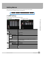
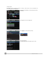
Setting Menus
When you press the [MENU] key during Free Running, the following menu screens appear.
The menu screens are classified by the tab for each setting item.
AMP
DATA
TRIG
OPT
OTHR
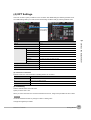
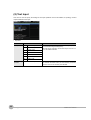
(1) AMP Settings
This menu is used to specify input signal-related settings.
<Analog Settings>
<Logic and Pulse Settings>
3
Selections available
Input
Off, Voltage, Temperature, Humidity
Range
[Voltage]
20, 50, 100, 200, 500 mV; 1, 2, 5, 10, 2
[Temperature]
TC-K, TC-J, TC-T, TC-R, TC-E, TC-B, TC-S
Filter
Line, A5, 50, 500Hz
EU
Function
(Scaling
settings) Measured Upper limit value
value
Lower limit value
Off, On
Misc.
SETTINGS AND MEASUREMENT
Setting
Numeric value input
Numeric value input
EU output Upper limit value
value
Lower limit value
Numeric value input
Decimal point
Select the display digit for decimal point (0 to 4).
Unit selection
Current, length, area, volume, speed, acceleration, frequency, weight, power,
pressure, flow, temperature
Numeric value input
Unit
(Selections vary depending on the selected units listed in the above.)
User-defined unit
Text input
Span
setting
Upper limit value
Numeric value input
Lower limit value
Numeric value input
Annotation setting
Text input (31 characters max.)
Waveform color setting
Red/Green/Blue (RGB) 0 to 31 available for each color
Perform Auto Zero ADJ.
Execute
Reset Auto Zero ADJ.
Execute
ZR-RX70 User’s Manual
Setting Menus
57
Setting
Selections available
Logic and Pulse
Off, Logic, Pulse
[Logic]
[Pulse]
Off, On
Input
Off, Revolution counts, Counts, Inst.
Filter
Off, On
↑ H, ↓ L
Slope
EU
Function
Off, On
Measured value Numeric value input
EU output value Numeric value input
Unit selection
Current, length, area, volume, speed, acceleration, frequency, weight, power,
pressure, flow, temperature
Unit
(Selections vary depending on the selected units listed in the above.)
User-defined unit Text input
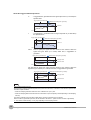
Switching displays
Analog and Logic/Pulse can be switched as shown below.
• Display Logic/Pulse Data
• Display Analog Data
A screen switches
with ENTER key.
Analog settings
This screen allows you to set conditions for analog signals.
Note
When selecting CH ALL at the Input and the Filter, all channels are set to the same setting. For the Range, the channels which are set to same setting of the Input are set to same range setting.
For the all channels Span setting, the channels which are set to same range setting are set to same span setting.
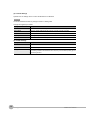
(1)-1 Input
Selects input conditions.
Selection
58
Description
Off
Disables the measurement of input signals and the waveform and digital display.
Voltage
Used for measuring direct-current voltages.
Temperature
Used for measuring temperatures.
Humidity
Used for measuring humidity with humidity sensor ZR-XRH1.
This selection sets the voltage range to 1V and disables EU settings.
Setting Menus
ZR-RX70 User’s Manual
(1)-2 Range
Specifies the range of signal input to be measured.
Input setting
Selection
Voltage
20, 50, 100, 200, 500mV; 1, 2, 5, 10, 20, 50, 100, 200, 500V; 1-5V
Temperature
TC-K, TC-J, TC-T, TC-R, TC-E, TC-B, TC-S, TC-N, TC-W
Humidity
No selection
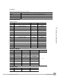
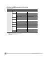
Available SPAN Settings
<Voltage Ranges>
Range
Maximum SPAN (measurement range)
Minimum SPAN
Minimum Resolution
0.200mV
0.001mV
50mV
–55.00 to +55.00mV
0.50mV
0.01mV
100mV
–110.00 to +110.00mV
1.00mV
0.01mV
200mV
–220.00 to +220.00mV
2.00mV
0.01mV
500mV
–550.0 to +550.0mV
5.0mV
0.1mV
1V
–1.1000 to +1.1000V
0.0100V
0.0001V
2V
–2.2000 to +2.2000V
0.0200V
0.0001V
5V
–5.500 to +5.500V
0.050V
0.001V
10V
–11.000 to +11.000V
0.100V
0.001V
20V
–22.000 to +22.000V
0.200V
0.001V
50V
–55.00 to +55.00V
0.50V
0.01V
100V
–110.00 to +110.00V
1.00V
0.01V
200V
–220.00 to +220.00V
2.00V
0.01V
500V
–550.0 to +550.0V
5.00V
0.1V
1-5V
–5.500 to +5.500V
0.050V
0.001V
SETTINGS AND MEASUREMENT
–22.000 to +22.000mV
3
20mV
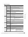
<Temperature Ranges>
Range
Maximum SPAN
Minimum SPAN (p-p) Measurement Range Minimum Resolution
K
–270 to +2000°C
50°C
–200 to +1370°C
J
–270 to +2000°C
50°C
–200 to +1100°C
T
–270 to +2000°C
50°C
–200 to +400°C
R
–270 to +2000°C
50°C
0 to +1600°C
E
–270 to +2000°C
50°C
–200 to +800°C
B
–270 to +2000°C
50°C
+600 to +1820°C
S
–270 to +2000°C
50°C
0 to +1760°C
N
–270 to +2000°C
50°C
0 to +1300°C
W
–270 to +2000°C
50°C
0 to +2000°C
0.1°C
<Humidity Range>
Range
Maximum SPAN
0 to +110%
ZR-RX70 User’s Manual
Minimum SPAN (p-p) Minimum Resolution
1.0%
0.1%
Setting Menus
59
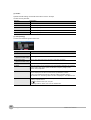
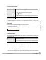
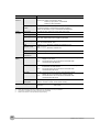
(1)-3 Filter
Specifies the filter setting. Use the filter when there is noise in the input.
The filter is a low-pass filter.
Selection
Description
Off
The filter is disabled.
Line
The cutoff frequency is 1.5 Hz.
5Hz
The cutoff frequency is 5 Hz.
50Hz
The cutoff frequency is 50 Hz.
500Hz
The cutoff frequency is 500 Hz.
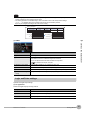
(1)-4 EU (Scaling)
Converts the measured signals to other units.
Setting
Description
(1) Function
Sets the function to ON or OFF.
(2) Meas. Value
Sets the upper and lower limits of the numeric value to be converted.
(Upper and Lower Limits)
(3) EU Output Value
Sets the upper and lower limits of the output value after conversion.
(Upper and Lower Limits)
(4) Dec pt
Specifies the decimal point position of the EU output value(s).
(5) Select
Selects the specific type of engineering units (The following selections are available).
Current, length, area, volume, speed, acceleration, frequency, weight, power,
pressure, flow, temperature
(6) Unit
Selects the converted unit.
The units displayed in this item are those of the type selected in “Select.”
To set a unit not displayed in this item, define an arbitrary character string in
“User-Defined Unit.” The setting made in this item is displayed in “User-Defined Unit”.
(7) User-Defined Unit
Selects the converted unit, which can be specified as a user-defined character string
consisting of alphanumerics.
For details on text input, see p.88.
The settings made in “Select” and “Unit” are reflected here.
60
Setting Menus
ZR-RX70 User’s Manual
Note
• If a message appears, follow the instructions by reducing the number of digits to be output by one, or leaving the
number of digits as is and changing the EU value.
• The Scaling operation is calculated using a ratio of the Meas. Value or EU Output Value settings.
“++++/- - - -” is displayed when the converted value cannot be processed by MT100.
Span may be changed according to the value set for Scaling.
Setting Example
Upper Value
Lower Value
Meas. Value
+5.000
–5.000
EU Value
+20.00
–20.00
+5V
+20.00 rpm
CH.1 10V
CH.1 Scaling 1
–5V
–20.00 rpm
Dec pt
Unit
+xx.xx
rpm
3
(1)-5 Misc.
Description
(1) Span
Sets the upper and lower limits of the span in which waveforms should be displayed.
(2) Annotation
Sets an annotation (comment) to be displayed for each channel.
The annotation can be 31 characters long at the maximum.
You can use alphanumeric and kana characters and symbols.
SETTINGS AND MEASUREMENT
Setting
For details on text input, see p.88.
(3) Waveform color setting
Red/Green/Blue (RGB) 0 to 31 available for each color
(4) Perform Auto Zero ADJ
Performs calculation using the current input voltage as the zero position voltage value.
(5) Reset Auto Zero ADJ
Cancels the zero position voltage value and displays the input voltage.
(6) [Zero Position Voltage
Value]
Displays the zero position voltage value (display only).
Logic and Pulse settings
Specifies the digital input settings.
(1)-6 Logic/Pulse
Selects the digital input processing method.
Setting
Description
Off
Disables the measurement of digital input.
Logic
Digital input is processed as logic signals.
Pulse
Digital input is processed as pulse signals.
ZR-RX70 User’s Manual
Setting Menus
61
Chap3.fm
Page 62
Friday, December 20, 2013
3:47 PM
(1)-7 Input
Sets the pulse measurement mode. This item can be set only when Pulse is selected in (1)-6.
Setting
Description
Off
Disables the pulse input.
Revol.
Counts the number of pulses per second and multiplies it by 60 to capture an rpm
value.
Counts
Captures the cumulative number of pulses for each sampling interval from the start of
measurement.
Inst.
Captures the number of pulses for each sampling interval.
(1)-8 Filter
Sets the filter for digital input.
Setting
Description
Off
Disables the filter.
On
Enables the filter. The filter is effective in an environment where there is lots of noise.
Filter is approximately 30 Hz (–3dB).
(1)-9 Slope
Sets the slope (direction) to count the number of pulses. This item can be set only when Pulse is selected in
(1)-6.
Setting
Description
↑H
Counts the rising edges of pulses.
↓L
Counts the falling edges of pulses.
(1)-10 EU (Scaling)
Converts the measured signals to other units.
➀
➁
➃
➂
➅
➄
Setting
Description
(1) Function
Sets On/Off of the Scaling function.
(2) Meas. Value
Sets the numeric value to be converted.
(3) EU Output Value
Sets the upper and lower limits of the output value after conversion.
(4) Select
Selects the specific type of engineering units (The following selections are available).
Current, length, area, volume, speed, acceleration, frequency, weight, power, pressure, flow, temperature
(5) Unit
Selects the converted unit.
The units displayed in this item are those of the type selected in “Select.”
To set a unit not displayed in this item, define an arbitrary character string in
“User-Defined Unit.” The setting made in this item is displayed in “User-Defined Unit”
(6) User-Defined Unit
Selects the converted unit, which can be specified as a user-defined character string
consisting of alphanumerics.
For details on text input, see p.88.
The settings made in “Select” and “Unit” are reflected here.
62
Setting Menus
ZR-RX70 User’s Manual
Note
• If a message appears, follow the instructions by reducing the number of digits to be output by one, or leaving the
number of digits as is and changing the EU value.
• The Scaling operation is calculated using a ratio of the Meas. Value or EU Output Value settings.
“++++/- - - -” is displayed when the converted value cannot be processed by MT100.
Span may be changed according to the value set for Scaling.
(2) DATA Settings
This menu is used to specify setting items related to capture and calculations.
<Capturing data to the internal RAM>
<Capturing data to the internal flash memory or USB memory>
3
Selection
Sampling Interval
10, 20, 50, 100, 200, 500us; 1, 2, 5, 10, 20, 50, 100, 200,
500ms; 1, 2, 5, 10, 20, 30s; 1min, External
Data capture destination
Internal RAM, Internal Flash Memory, USB Memory
[Internal RAM]
SETTINGS AND MEASUREMENT
Setting
Number of capture points 10 to 1000000
Auto Save
[On]
Off, On
File Name
[Internal Flash Memory] File Name
or
[USB Memory]
* See the following section on the data capture
* See the following section on the data capture
Function 1
Off, Average, Max, Min, Peak, RMS
Function 2
Off, Average, Max, Min, Peak, RMS
Data capture file name
Setting
Selection
Folder (File)
Destination : MEM, USB1
Folder
: Text input (if it is automatically named)
File
: Text input (if it is user-defined)
Name Type
Auto or User
File Format
Binary (GBD), Text (CSV)
ZR-RX70 User’s Manual
Setting Menus
63
Chap3.fm
Page 64
Friday, December 20, 2013
3:45 PM
(2)-1 Sampling Interval
Specifies intervals used to capture data.
Capture destination
Selections available
Internal RAM
10, 20, 50, 100, 200, 500us; 1, 2, 5, 10, 20, 50, 100, 200, 500ms; 1, 2, 5, 10, 20, 30s; 1min,
External
Internal flash memory 1, 2, 5, 10, 20, 50, 100, 200, 500ms; 1, 2, 5, 10, 20, 30s; 1min
USB memory
1, 2, 5, 10, 20, 50, 100, 200, 500ms; 1, 2, 5, 10, 20, 30s; 1min
Important
When the External Sampling is set, data is captured at 10µs as internal processing. Then, the input of an external
pulse allows the next internal processing data to be written into the memory.
Therefore, both capturing interval and input error become up to 10µs.
You can use the external sampling function to the extent that the input error can be ignored.
Input signal
External sampling
pulse
Internal processing
data capturing
interval
Data captured to
memory
10s
This data
This data
Note
• When the data capture destination is the internal flash memory or USB memory and the capture file format is Text
(CSV), sampling intervals from 1 to 5ms cannot be selected.
• When External is selected in the sampling interval, you cannot select External Input in the trigger setting. When
the External Input is already set, the trigger is changed to Off.
64
Setting Menus
ZR-RX70 User’s Manual
(2)-2 Data Capture Destination
Specifies the data capture destination for captured data.
Selection
Description
Internal RAM
Captures the measured data to the internal RAM. The data will be lost when the power is
turned off. The data will be overwritten when next data is captured.
Check the waveform and, if it is OK, press the [File] key to save the data.
See p.80.
If Auto Save is set to On, data will be automatically saved.
See “(2)-4 Auto Save” p. 66.
This selection can be used for any sampling interval. Specify this selection if you
want to capture data at higher rates than 500 us.
This selection comes in handy for saving the memory space if you check the waveform of
captured data first and save only necessary data.
Note
USB memory
Sampling intervals from 1 to 5ms cannot be selected when the capture file format
is Text (CSV).
SETTINGS AND MEASUREMENT
Note
3
Internal flash memory Captures the measured data to the internal flash memory. The data once captured is retained
even after the power is turned off. This selection cannot be specified if the sampling interval is
from 10 to 500us. Select a sampling interval lower than 1ms..
Captures the measured data to the USB memory. The data once captured is retained even
after the power is turned off. This selection cannot be specified if the sampling interval is from
10 to 500 us. Select a sampling interval lower than 1 ms.
Note
• Sampling intervals from 1 to 5ms cannot be selected when the capture file format is Text
(CSV).
• Large-capacity USB memory can also be used. The use of USB memory comes in
handy when you want to capture data many times or the capacity of internal flash memory is not sufficient for long measurement (Data up to 2GB can be captured per data
capture).You cannot use USB memory with a security function such as fingerprint
authentication or with no shell (metallic part) in the connector area.
Data lost after power-off
Measured data
Internal RAM
Data retained after power-off
Saving data
or
Auto Save
Internal flash memory
or USB memory
(2)-3 Number of Capture Points
Specifies the number of data points to be captured to the internal RAM. This item can be set only when Internal
RAM is selected in (2)-2.
Before setting this item, check the time available for data capture ((A) in the figure).
ZR-RX70 User’s Manual
Setting Menus
65
(2)-4 Auto Save
Specifies whether to automatically save data captured to the internal RAM. This item can be set only when
Internal RAM is selected in (2)-2.
Selection
Description
Off
Disables auto save of data. Data captured to the internal RAM is lost when the power is
turned off or next data is captured.
If you want to keep data, press the [FILE] key to save the data.
On
Enables auto save of data. Data captured to the internal RAM is saved either to the internal
flash memory or USB memory.
When you set a faster sampling interval or increase the number of captured
data, the auto save process may not be completed by the time a data capture to
the internal RAM ends. In such a case, you cannot start the next capture with the [Start/
STOP] key until the current auto save is completed.
If you want to stop the auto save process in progress, press the [FILE] key to open the
menu screen and select Stop Auto Save on the screen.
The data already saved is retained even if you stop the auto save process in progress.
Note
(2)-5 File Name
Specifies the name of a file or folder to which you want to capture data or auto-save data.
<If the Name Type is Auto>
<If the Name Type is User>
Setting
Description
(1) Folder
Specifies a folder to which you want to capture (or save) data.
For details, see the file box on p.85.
(2) File
Specifies a file to which you want to capture (or save) data.
For details, see the file box on p.85.
(3) Name Type
66
Setting Menus
Sets how a data file is named.
Auto
: Automatically gives a name to a file.
Example: 20050101-123456_UG.GBD
Number part.........Date and time at which a file was created
* In this example, the date is January 1, 2005 and the
time is 12:34:56.
UG .......................User number for data capture
UG (Guest)
U1 (User 1)
U2 (User 2)
GBD.....................Data format
GBD (Binary format)
CSV (Text format)
When the Repeated capturing is On, the text of “rep” showing repeat and a
number showing the number of times of repeating are added as shown by
20050101-123456_UG_rep001.GBD.
User
: Captures data to a file with a user-defined name.
ZR-RX70 User’s Manual
Setting
Description
(4) File Format
Sets the file format in which you want to save data.
GBD
: Creates a data file in Omron proprietary binary format.
* Prevents tampering of data.
CSV
: Creates a data file in a text format.
* Cannot be replayed on the ZR-RX70.
When the data capture destination is the internal flash memory or USB
memory and the sampling interval is from 1 to 5 ms, you cannot select CSV.
Select a sampling interval lower than 10ms.
Important
• If you perform data capture with Name Type set to Auto, data will be saved in folders automatically created with the
date and time as their respective names (The time folder is created below the date folder).
• If you perform data capture repeatedly with Name Type set to Auto, after certain number of files are captured, a new
time folder is created and data is captured to the folder.
3
• When you save files, create a folder and then save the files in the folder.
Regardless of the remaining capacity, if you try to save files in the root directory, due to file restrictions you may not
SETTINGS AND MEASUREMENT
be able to save files.
• The displayed Capture Time may vary according to the sampling interval or number of capture channels.
Note
Changing the sampling interval, capture destination, or number of capture
points will change the screen display of the time available for data capture,
capacity available for data capture, and possible number of times of repeating. If you find that the measuring time exceeds the capacity available for
data capture, either change the sampling interval or capture destination (to
large-capacity USB memory).
Time available for data capture .................... Indicates how long data can be
captured.
Capacity available for data capture .............. Indicates the capacity available
for data capture with the memory size if the data capture destination is the internal flash memory or
USB memory. The figure shown in brackets is the percentage of free
memory space to the total memory size.
Possible number of times of repeating......... Indicates how many times data captured to the internal RAM can be
saved to the save destination device if Auto Save is set to On. Beware
of using this setting particularly when Repeated Capturing is set to On
for the trigger.
For details, see “(3) TRIG Settings” p. 69
The time available for data capture is calculated for data up to 2GB. If the capacity of free USB memory is 2GB or
more, "over" is displayed.
When the time available for data capture (for 2GB) is exceeded, after the data of 2GB is captured, the capture of
remaining data is automatically resumed to another file.
The data between the stop and resumption of the capture process is not captured when the sampling interval is too
fast.
ZR-RX70 User’s Manual
Setting Menus
67
(2)-6 Statistical Calculation Settings
The ZR-RX70 can perform two statistical calculations.
This section describes specifying the statistical calculation settings.
Selection
Description
Off
Calculation is not performed.
Average
Displays the simple average value of data being captured.
Max
Displays the maximum value of data being captured.
Min
Displays the minimum value of data being captured.
Peak
Displays the peak value of data being captured.
RMS
Displays the effective value of data being captured.
The calculation formula is as shown below.
D: data
n: number of data
Note
• The calculation results are displayed in the Digital + Statistical Calculation Display screen. Switch to the Full
Channels + Statistical Calculation Display using the and keys.
For details, see “(6) Direction keys” p. 47
• Calculation will start upon power ON. Pressing the [START] key to begin measurement will clear the calculation.
• The sampling speed for calculation corresponds to the speed set in the DATA menu. However, when the sampling
speed is higher than 5ms, it is set to 5ms.
68
Setting Menus
ZR-RX70 User’s Manual
(3) TRIG Settings
This menu is used to specify trigger conditions and alarm settings.
Selections available
Timer mode
Off, Date and Time, Every Day Cycle, Every Hour Cycle
3
Setting
SETTINGS AND MEASUREMENT
[Date and Time] Start side source setting Date January 1, 2005 to December 31, 2035
Time 00:00 to 23:59 (Hour:Minute)
Stop side source setting Date January 1, 2005 to December 31, 2035
Time 00:00 to 23:59 (Hour:Minute)
[Every Day
Cycle]
Start side source setting Time 00:00 to 23:59 (Hour:Minute)
[Every Hour
Cycle]
Start side source setting Time 00:00 to 59:59 (Minute:Second)
Stop side source setting Time 00:00 to 23:59 (Hour:Minute)
Stop side source setting Time 00:00 to 59:59 (Minute:Second)
Start side source setting
[Level]
Off, Level, External Input, Time
Combination
Level OR, Level AND, Edge OR, Edge AND
Mode
Analog : Off, ↑ H, ↓ L, Win In, Win Out
Logic : Off, ↑ H, ↓ L
Pulse : Off, ↑ H, ↓ L, Win In, Win Out
Level
Numeric value setting
[Time]
0000:00:01 to 9999:59:59 (Hour:Minute:Second)
Stop side source setting
[Level]
[Time]
Off. Level, External Input, Time
Combination
Level OR, Level AND, Edge OR, Edge AND
Mode
Analog : Off, ↑ H, ↓ L, Win In, Win
Logic : Off, ↑ H, ↓ L
Pulse : Off, ↑ H, ↓ L
Level
Numeric value setting
0000:00:01 to 9999:59:59 (Hour:Minute:Second)
Pre-trigger
0, 10, 20, 30, 40, 50, 60, 70, 80, 90, 100%
Repeated capturing
Off, On
Repeat interval
0000:00:00 to 9999:59:59 (Hour:Minute:Second)
Timer trigger information
Alarm
level
settings
Display Information
Alarm Hold
Off, On
Mode
Analog : Off, ↑ H, ↓ L, Win In, Win
Logic : Off, ↑ H, ↓ L
Pulse : Off, ↑ H, ↓ L
Level
Numeric value setting
Output
1, 2, 3, 4
ZR-RX70 User’s Manual
Setting Menus
69
(3)-1 Timer Mode
Sets the timer function.
When the timer function is used (set to a selection other than OFF), data capture is enabled only during the
time for which the timer is set.
Selection
Description
Off
The timer function is not used. Data capture starts according to triggers.
Date and Time
Data capture starts when a trigger is generated only during certain (specified) date and
time.
⇒ When Date and Time is selected, set the date and time both on the start and stop
sides.
Every Day Cycle
Data capture starts when a trigger is generated only during the same (specified) time
every day.
⇒ When Every Day Cycle is selected, set the time (hour and minute) both on the
start and stop sides.
Every hour cycle
Data capture starts when a trigger is generated only during the same (specified) time
every hour.
⇒ Set the time (minute and second) both on the start and stop sides.
The actual timing conditions for data capture are related to triggers.
See also Sections “(3)-2 Start Side Source Settings” p. 70, “(3)-3 Stop Side Source Settings” p. 71,
and “(3)-7 Timer Trigger Information” p. 72.
(3)-2 Start Side Source Settings
Specifies trigger conditions to start data capture.
Selection
Description
Off
Starts capturing data unconditionally (when the [START/STOP] key is pressed or the
time specified for the timer function arrives).
Level
Starts capturing data when a specified level condition is met.
⇒ When Level is selected, set the condition for each channel.
See p.72.
External Input
Starts capturing data when an input signal is received from an external trigger terminal.
* A trigger is generated when the voltage changes from 5V (open) to 0V (short circuit
to GND).
Time
Data capture starts after a specified length of time elapses after the [START/STOP] key
is pressed or the time specified for the timer function is reached.
⇒ When Time is selected, set the time to start capturing data.
The actual timing conditions for data capture are related to the timer.
See also Sections “(3)-1 Timer Mode” p. 70, “(3)-3 Stop Side Source Settings” p. 71, and “(3)-7 Timer
Trigger Information” p. 72.
70
Setting Menus
ZR-RX70 User’s Manual
(3)-3 Stop Side Source Settings
Specifies trigger conditions to stop data capture.
Selection
Description
Off
Stops capturing data unconditionally (when the [START/STOP] key is pressed or the
time specified for the timer function arrives).
Level
Stops capturing data when a specified level condition is met.
⇒ When Level is selected, set the condition for each channel.
See p.72.
External Input
Stops capturing data when an input signal is received from an external trigger terminal.
* A trigger is generated when the voltage changes from 5V (open) to 0V (short circuit
to GND).
Time
Stops capturing data after a specified length of time elapses after starting data capture.
⇒ When Time is selected, set the time after which you want to stop capturing data.
The actual timing conditions for data capture are related to the timer.
3
SETTINGS AND MEASUREMENT
See also Sections “(3)-1 Timer Mode” p. 70, “(3)-2 Start Side Source Settings” p. 70, and “(3)-7 Timer
Trigger Information” p. 72.
(3)-4 Pre-trigger
Specifies the percentage of data to be captured before a trigger is generated.
* Pre-trigger can be selected only when the data capture destination is the internal RAM and the start side
source setting is other than OFF.
If the pre-trigger is 30%
Time available for data capture
30%
Start side trigger
(3)-5 Repeated Capturing
Sets the repeat function for repeated capturing.
This selection can be specified when the data capture destination is the internal RAM or the stop side source
setting is other than Off.
Selection
Description
Off
The repeat function is not used.
On
The repeat function is used.
After one data capture process ends, the next data capture process starts (or a trigger
is waited for if the start side source setting is other than Off).
(3)-6 Repeat Interval
Specifies the interval from the start of one data capture process to the start of another data capture process if
the repeat function is used.
This selection can be specified when the following three conditions are all met:
• the Repeated capturing is On,
• the start side source setting is Off or Time, and
• the stop side source setting is set to Time, or the stop side source setting is set to Off and the data capture
destination is set to Internal RAM.
ZR-RX70 User’s Manual
Setting Menus
71
(3)-7 Timer Trigger Information
Displays the timer and trigger information in an easy-to-understand manner.
Example
Timer Mode: Every Day Cycle
Start Side Source Setting: Level
Stop Side Source Setting: Time
Repeated Capturing: On
A trigger generated in this interval
will not start data capture.
Data capture is enabled only in this interval.
Data is actually captured in this interval.
* This is only a conceptual illustration in which the graph length, number of times of repetition, and other items
do not agree with the actual time.
(3)-8 Alarm Setting
Specifies alarm generation conditions and output destinations. When the conditions specified here are met, an
alarm is output from the alarm output terminal (specify the output destination number for each channel).
With “Hold Generated Alarm” set to “Hold”, the alarm status is maintained after the conditions are met once
even if they do not continue to be met (Press the [CURSOR] key to clear the alarm).
See “Trigger Level Settings/Alarm Level Settings” p. 72.
Trigger Level Settings/Alarm Level Settings
If the start side source setting or stop side source setting is “Level”, specify detailed conditions for each channel.
The overall structure of level triggers are as shown below.
CH n
Mode
Level
Pulse n
Mode
Level
Logic n
Mode
Pattern
Comparison
Combination
* Pulse and Logic are toggled back and forth.
* The Logics 1 to 4 are fixed to pattern comparison.
<Trigger Level Settings>
72
Setting Menus
Trigger
CH n
Mode
Level
Pulse n
Mode
Level
Logic n
Mode
Level
Or
Alarm output n
* Pulse and Logic are toggled back and forth.
* Specify an alarm output destination for Pulse and Logic for each channel.
The conditions are ORed for each alarm output destination.
Example) Suppose CH1 and CH2 are set to Output 1 and CH3 and CH4 to Output 2.
If either CH1 or CH2 meets the conditions, Alarm Output 1 occurs.
If either CH3 or CH4 meets the conditions, Alarm Output 2 occurs.
<Alarm Settings>
ZR-RX70 User’s Manual
(1) Combination
Sets the combination of trigger conditions set for each channel.
Level OR : Starts (stops) capturing data when at least one trigger condition is met.
Each condition is a level operation.
Level AND : Starts (stops) capturing data when all trigger conditions are met. Each
condition is a level operation.
Edge OR : Starts (stops) capturing data when at least one trigger condition is met.
Each condition is an edge operation.
Edge AND : Starts (stops) capturing data when all trigger conditions are met. Each
condition is an edge operation.
(2) Mode
Specifies the mode for trigger comparison for each channel.
Off
: Disables triggers for the set channel.
↑ H (Rising): Generates a trigger when an input signal is above the specified level.
↓ L (Falling): Generates a trigger when an input signal is below the specified level.
Win In
: Generates a trigger when an input signal is (has come) between the
upper and lower limit levels set for each channel.
* There is no setting for a logic channel.
Win Out
: Generates a trigger when an input signal is not (has moved out from)
between the upper and lower limit levels set for each channel.
* There is no setting for a logic channel.
(3) Level
Specifies the level for trigger comparison.
Set one level for comparison if the mode is set to ↑ H (Rising) or ↓ L (Falling).
Set two levels for comparison if the mode is set to Win In or Win Out.
(4) Hold Generated Alarm
Specifies the operation that occurs when the alarm conditions are met once and then
are no longer met.
Hold
: Maintains the alarm status when the alarm conditions are met once and
then are no longer met. (Press the [CURSOR] key to clear the alarm).
Do Not Hold: Clears the alarm status when the alarm conditions are met once and then
are no longer met.
SETTINGS AND MEASUREMENT
Description
3
Setting
About Level and Edge Operations
In the level operation, the trigger conditions are assumed to be met only if they are met when the [START] key
is pressed (after the timer reaches the set time).
In the edge operation, the trigger conditions are assumed NOT to be met even if they are met when the
[START] key is pressed (after the timer reaches the set time).
The trigger conditions are assumed to be met only if they are no longer met and then are met again.
Example) If the mode is Rising
Trigger generation area
The START key is pressed here.
An edge that
exceeds the
setting level
is needed.
Measurement immediately
starts in the level operation.
Setting level
Measurement starts here
in the edge operation.
Important
There is an error of ±1% at the maximum to the range between the trigger setting level and the level at which
the trigger is actually generated (trigger generation level), e.g. ±0.01V in the 1V range. Approx. 1.3% of trigger
hysteresis is provided to the trigger generation level. Approx. 0.5% of alarm hysteresis is provided.
ZR-RX70 User’s Manual
Setting Menus
73
About the Trigger and Alarm Operations
H
: A trigger/alarm is generated when the signal input rises to (or exceeds) the
specified level.
Trigger (alarm) generated area
Measurement starts (alarm generated)
Set level
CH.1
L
: A trigger/alarm is generated when the signal input falls to (or falls below)
the specified level.
Trigger (alarm) generated area
Measurement starts (alarm generated)
Set level
CH.1
Win In : Used to specify the upper and lower limits for each channel. When the
signal level goes within (or is within) either limit, a trigger/alarm is
generated.
Trigger (alarm) generated area
Measurement starts (alarm generated)
Set upper level
Set lower level
CH.1
Win Out:Used to specify the upper and lower limits for each channel. When the
signal level goes outside (or is outside) either limit, a trigger/alarm is generated.
Trigger (alarm) generated area
Measurement starts (alarm generated)
Set upper level
Set lower level
CH.1
Note
Alarm judgment interval is 5ms.
Since the alarm judgment and data capture are asynchronous each other, a deviation occurs between captured data
and alarm output as follows:
• When the sampling interval is slower than 5ms: a deviation of up to 1 point
• When the sampling interval is faster than 5ms: a deviation of up to 500 points (it varies depending on the sampling
interval)
The alarm is cleared once at the start of data capture, and then compared at 5-ms intervals.
When an alarm is generated upon start, the first few data*1 becomes “L” (status in which no alarm is generated).
*1: The number of data showing “L” may vary depending on the sampling interval.
74
Setting Menus
ZR-RX70 User’s Manual
(4) OPT Settings
This menu is used to specify conditions for PC connection and USER settings for switching between users.
The USER settings allow you to read out the stored setting conditions easily by switching between users.
A screen switches
with ENTER key.
3
Selections available
USB ID
0 to 9
IP Address
0 to 255. 0 to 255. 0 to 255. 0 to 255
Detailed Settings
New Line Code
SETTINGS AND MEASUREMENT
Setting
CR+LF, LF, CR
USB ID
0 to 9
IP Address
0 to 255. 0 to 255. 0 to 255. 0 to 255
Subnet Mask
0 to 255. 0 to 255. 0 to 255. 0 to 255
Port Number
1024 to 65535
Gateway
0 to 255. 0 to 255. 0 to 255. 0 to 255
DNS Address
0 to 255. 0 to 255. 0 to 255. 0 to 255
Setting Condition Switching
Guest, User 1, User 2
User
Text input (when User is set)
Department Name
Text input (when User is set)
(4)-1 End-of-Line Character
Specifies a New Line code used when controlling with the I/F command.
Selection
Description
CR+LF
Starts a new line with CR+LF codes.
LF
Starts a new line with LF code.
CR
Starts a new line with CR code.
(4)-2 USB Setting
Sets the USB ID number of the ZR-RX70.
Specify a number from 0 to 9.
When you control more than one unit of the ZR-RX70 with one PC, assign a unique USB ID to each of them.
Important
You must restart MT100 after any change is made to a setting value.
Changes are applied upon restart.
ZR-RX70 User’s Manual
Setting Menus
75
(4)-3 TCP-IP Settings
Specifies TCP-IP settings used to connect the ZR-RX70 to an Ethernet.
Important
You must restart MT100 after any change is made to a setting value.
Changes are applied upon restart.
Setting items
Description
IP Address
Sets the IP address of MT100 (0 to 255. 0 to 255. 0 to 255. 0 to 255).
Subnet Mask
Sets the IP subnet mask of MT100 (0 to 255. 0 to 255. 0 to 255. 0 to 255).
Port Number
Sets the port number of MT100 (1024 to 65535).
Gateway
Sets the gateway of MT100 (0 to 255. 0 to 255. 0 to 255. 0 to 255).
DNS Address
Sets the DNS address of MT100 (0 to 255. 0 to 255. 0 to 255. 0 to 255).
(4)-4 USER Settings
76
Setting items
Description
User
Specifies the user name. You cannot set this item when Guest is selected.
Department name
Specifies the department name. You cannot set this item when Guest is selected.
Change Conds
Switches between Guest, User 1, and User 2.
Since setting conditions are stored for each user, they can be called up easily by simply switching the user.
Setting Menus
ZR-RX70 User’s Manual
(5) OTHR Settings
Other miscellaneous settings are made here.
Selections available
LCD Brightness
Light, Medium, Dark
Off; 10, 30 (sec.); 1, 2, 5, 10, 30, 60 (min.)
Power On Start
Disable, Enable
Room Temp.
Internal, External
Temp. Unit
°C, °F
Background color
Black, White
Start/Stop Confirmation Message
On, Off
Date/Time Date/Time
Date
January 1, 2005 to December 31, 2035
Time
00:00:00 to 23:59:59 (Hour:Minute:Second)
Network Time
SETTINGS AND MEASUREMENT
Screen Saver
3
Setting
Off, On
Time Server
Text Input
Time Zone
–12:00 to +13:00 (one-hour steps)
Synchronized Time
00:00 to 23:59 (Hour:Minute)
Synchronization Mode Immediately, Gradually
Connection Test
Language
Return to Default Settings
Execute
Japanese, English (US), English (UK), French, German, Chinese,
Korean
Execute
Demo Waveform Mode
Off, On
Game
Memory test game, Number order game, Reversi, Blackjack,
Speed...
Information
Show Information
(5)-1 LCD Brightness
Sets the brightness of the LCD backlight.
(5)-2 Screen Saver
Automatically turns off the display if the ZR-RX70 is not operated within a specified interval.
Turning off the display frequently using the screen Saver function allows longer lifetime of the LCD screen.
ZR-RX70 User’s Manual
Setting Menus
77
(5)-3 Power On Start
Sets the feature that automatically starts measurement when the ZR-RX70 is powered on.
Selection
Description
Disable
Disables the Power On Start function.
Enable
Enables the Power On Start function.
(5)-4 Room Temp. Compensation
Specifies the room temperature compensation in temperature measurement using a thermocouple.
Selection
Description
Internal
The ZR-RX70’s room temperature compensation settings are used.
(Usually you use this parameter.)
External
Set this parameter to use the room temperature compensation settings in external
devices.
(5)-5 Temp. Unit
Toggles the temperature unit between °C (Celsius) and °F (Fahrenheit). (Selecting °F forcibly enables the
scaling function.)
When °F (Fahrenheit) is selected, the calculation formula is as shown below.
°F (Fahrenheit) = °C (Celsius) x 1.8+32
Accuracy is calculated using the formula; Accuracy at Celsius x 1.8.
(5)-6 Background Color
Sets the background color of the waveform and digital display areas.
(5)-7 Start/Stop Confirmation Message
Specifies the setting of the confirmation message displayed when data capture is started and stopped.
Selection
Description
On
Enables the confirmation message. Pressing the [START/STOP] key brings up the message, confirming whether you want to start (or stop) data capture. Pressing the Enter key
starts (or stops) data capture.
Off
Disables the confirmation message. Pressing the [START/STOP] key immediately
starts (or stops) data capture without displaying the message.
(5)-8 Date/Time
Sets the clock of the ZR-RX70.
Sets the built-in clock (Date/Time) of the ZR-RX70. If Network Time is set, the clock of the ZR-RX70 is
automatically adjusted via the network. For details, see “Network Time Settings” p. 79.
(5)-9 Language
Sets the ZR-RX70’s display language.
(5)-10 Demo Waveform Mode
Displays demo waveforms without analog signal input.
Selection
Description
Off
Do not display demo waveforms.
On
Display demo waveforms.
(5)-11 Return to Default Settings
Initializes the settings. After initialization, the settings are reset to the factory defaults.
78
Setting Menus
ZR-RX70 User’s Manual
(5)-12 Game
Games are available. The score is stored for each user.
(5)-13 Information
Displays system information for the ZR-RX70.
Network Time Settings
The ZR-RX70 synchronizes the time of the built-in clock with that of a time server via an Ethernet.
Description
Network Time
Enables or disables this feature.
Off: Disables this feature. The time adjustment is not performed.
On: Enables this feature. The time adjustment is performed.
Time Server
Specifies the domain name of the time server to be used.
Time Zone
Sets the time zone of the area in which the ZR-RX70 is to be used (Japan: +09:00).
Synchronized Time
Sets the time at which the ZR-RX70 clock is to be synchronized with the time server.
When the setting time comes, the synchronization operation in the local country is performed with a method specified in Synchronization Mode.
Synchronization Mode
Immediately, Gradually
Sets a method in which the clock is to be synchronized with the time server.
Immediately: Immediately synchronizes the clock with the time server when the time for
synchronization comes.
Gradually : Does not immediately synchronize the clock when the time for synchronization comes.
Gradually synchronizes the clock with the time server.
The adjusted length of time is about 43 seconds per day (approximately
equal to 10 ms per 20 seconds).
Connection Test
Performs a connection test by connecting to the time server.
After the connection test is performed, a message is displayed.
If connection fails, check the settings and conduct the connection test again.
If the connection test is a success, the following message is displayed.
3
Setting
SETTINGS AND MEASUREMENT
Important
The synchronization is not performed if the error with the time server is 500 ms or more.
The synchronization accuracy with the time server is approx. 10ms. (It may exceed 10ms in some network environments.)
ZR-RX70 User’s Manual
Setting Menus
79
(6) FILE Menu
Performs file-related operations. The items displayed vary depending on the operation mode.
File replay is explained in detail on p.54.
When the data in the internal RAM is being replayed, “Next File” and “Previous File” are not displayed.
<Free Running>
<Replaying>
<Capturing/Capturingand Replaying>
<Auto Saving>
<X-Y Display Screen>
(6)-1 File Replay and Operation
Replay data or operate files in the internal flash memory or USB memory.
File replay is explained in detail on p.85.
80
Setting Menus
ZR-RX70 User’s Manual
(6)-2 Data Save
Save data remaining in the internal RAM to the internal flash memory or USB memory.
<If the Name Type is Auto>
<If the Name Type is User>
(1) File Format
Sets the file format in which you want to save data.
GBD
: Creates a data file in Omron proprietary binary format.
* Prevents tampering of data.
CSV
: Creates a data file in a text format.
* Cannot be replayed on the ZR-RX70.
(2) Name Type
Sets how a data file is named.
Auto
: Automatically gives a name to a file.
Example: 20050101-123456_UG.GBD
Number part.........Date and time at which a file was created
* In this example, the date is January 1, 2005 and the
time is 12:34:56.
UG .......................User number for data capture
UG (Guest)
U1 (User 1)
U2 (User 2)
GBD.....................Data format
GBD (Binary format)
CSV (Text format)
User
: Captures data to a file with a user-defined name.
(3) Folder
Specifies a folder to which you want to save data.
SETTINGS AND MEASUREMENT
Description
3
Setting
For details, see the file box on p.85.
(4) File
Specifies a file to which you want to save data.
For details, see the file box on p.85.
ZR-RX70 User’s Manual
Setting Menus
81
(6)-3 Bitmap Save
The ZR-RX70 can save a screen copy of waveforms, etc. to a bitmap file. This menu is used to specify the
save destination, file name, etc. of a bitmap file.
<If the Name Type is Auto>
<If the Name Type is User>
Setting
Description
(1) Folder
Specifies a folder to which you want to save data.
For details, see the file box on p.85.
(2) File
Specifies a file to which you want to save data.
For details, see the file box on p.85.
(3) Name Type
Sets how a data file is named.
Auto
: Automatically gives a name to a file.
Example: 20050101-123456_UG.GBD
Number part.........Date and time at which a file was created
* In this example, the date is January 1, 2005 and the
time is 12:34:56.
UG .......................User number for data capture
UG (Guest)
U1 (User 1)
U2 (User 2)
BMP.....................Data format (Bitmap file)
User
: Captures data to a file with a user-defined name.
(4) Screen Type
Selects the type of the screen to be saved.
Full screen: Saves the entire screen currently displayed. This type cannot be used for
X-Y overlay.
Waveform screen: Saves the waveform display area only (the digital display area is
not displayed). To use X-Y overlay in the X-Y Display screen,
select this screen type.
(6)-4 Execute
Save a screen copy to a bitmap file.
For information on specifying the save destination, see “(6)-3 Bitmap Save” p. 82.
82
Setting Menus
ZR-RX70 User’s Manual
(6)-5 Save
Save the settings of the ZR-RX70.
<If the Name Type is Auto>
<If the Name Type is User>
Setting
Description
(1) Folder
Specifies a folder to which you want to save data.
For details, see the file box on p.85.
(2) File
Specifies a file to which you want to save data.
For details, see the file box on p.85.
(3) Name Type
3
Sets how a data file is named.
Auto
: Automatically gives a name to a file.
Example: 20050101-123456_UG.GBD
Number part.........Date and time at which a file was created
* In this example, the date is January 1, 2005 and the
time is 12:34:56.
UG .......................User number for data capture
UG (Guest)
U1 (User 1)
U2 (User 2)
CND.....................Data format (Settings file format of the ZR-RX70)
User
: Captures data to a file with a user-defined name.
SETTINGS AND MEASUREMENT
(6)-6 Load
Loads the settings of the ZR-RX70 from a file.
Setting
Description
(1) Folder
Specifies a folder to which you want to save data.
For details, see the file box on p.85.
ZR-RX70 User’s Manual
Setting Menus
83
Chap3.fm
Page 84
Friday, December 20, 2013
3:47 PM
(6)-7 Next File, Previous File
Replays the previous or next file of the file being currently replayed.
The file order corresponds to the file display order set in the File Replay and Operation ("ascending order of
name," "descending order of name," "ascending order of created date and time," or "descending order of
created date and time" can be specified).
This function allows search one folder above.
<File Tree Structure (image)>
MEM
Folder1
Folder3
File1
File2
File3
Folder4
File4
This file can be
replayed sequentially.
File5
File6
Folder2
Folder5
File7
(6)-8 Stop Auto Save
Stops the auto save process being currently performed. The file to which any data has been already written
until stop will be retained.
(6)-9 X-Y Overwrite
Overwrite the X-Y image on a thumbnail-size image of the captured data in the X-Y Display screen as a
background. This overwrite function enables waveform comparison.
Note
A thumbnail-size image is automatically generated when the data capture destination is the internal flush memory or
USB memory and saved in the same folder as the captured data (the file format is BMP file).
Also, the waveform screen saved to a bitmap file during replay can be used for overwrite.
Setting
Description
(1)Image Selection
Selects the image to overwrite. The method for selecting an image file is the same as
for selecting data to replay.
Important
You cannot use the bitmap file saved by specifying Full screen for overwrite.
(2) Overwrite Clearing
Clear the overwrited image. When you do this operation during Free Running, all
images will be cleared. When you do this operation during replay, the image of the data
currently being replayed is retained.
Important
Irregularity may occur on the X-Y screen depending on setting conditions such as high sampling interval. Even in that
case, the captured data itself will not be affected.
You can save the image replayed from the captured data in a bitmap file as the waveform image and use it as source
image for comparison.
84
Setting Menus
ZR-RX70 User’s Manual
(7) File Box
Use the file box to specify a data save destination from the DATA menu or to replay and operate data from the
FILE menu.
<File box for Data Replay and Operation>
3
Description
SETTINGS AND MEASUREMENT
Key
Change the operation of the file box.
Show properties ............................. Displays details of a file or folder.
Select file/folder ............................. Selects files or folders to write data.
Create new folder .......................... Creates a new folder.
Create new file ............................... Creates a new file.
Rename ......................................... Changes the file or folder name.
Copy file/folder ............................... Copies files or folders.
Select file to copy/delete ................ Selects the file to copy or delete.
Select copy destination and copy .. Selects the copy destination and copies.
Delete file/folder ............................. Deletes files or folders.
File sort order................................... Changes the order in which files are displayed.
View setting.................................... Changes displaying information for files.
Format disk .................................... Formats the disk.
* Details of allowed operation will depend on the operation target.
Moves between folders.
: Move up one folder.
: Move down one folder.
ENTER
Finalizes the operation.
QUIT
Closes the file box.
ZR-RX70 User’s Manual
Setting Menus
85
<Setting example>
The following shows an operation example for creating a “TEST” folder as the save destination and
automatically saving captured data into it.
In the [Data Save Destination], choose [Folder] and press the
[ENTER] key.
Use the
Use the
key to move to the target folder.
key to select [Create new folder].
Press the [ENTER] key.
In the [New folder name] box that appears, type in “TEST”.
86
Setting Menus
ZR-RX70 User’s Manual
Use the
key to choose [Select file/folder].
Use the
key to move the cursor to the created “TEST”
folder, and press the [ENTER] key.
3
SETTINGS AND MEASUREMENT
Select [OK] to close the screen.
ZR-RX70 User’s Manual
Setting Menus
87
(8) Text Input
This menu is used to specify the settings of text input operations such as annotation, EU (scaling) unit and
captured data file name input.
• Operation
Operation mode Description
Text input
A
0
Upper case alphabet mode When the cursor key is moved to the uppermost part, operation
can be selected using the left/right key.
Lower case alphabet mode
After selecting an operation, use the down key to move the cursor to the desired character.
Numeric mode
+
Symbol mode
←
Delete mode
↓
Insert mode
OK
Finalize mode
a
When selecting
operation
88
Setting Menus
Operation method
Text used for each operation
When you bring the cursor to a character and press ENTER,
the character is entered. After you finish entering characters,
move the cursor to OK and then press ENTER.
ZR-RX70 User’s Manual
(9) Data Replay Menu
When you press the [MENU] key during replay, the Data Replay Menu is displayed.
Setting
Move to First Data
Execute
Execute
Move to Center
Execute
Move to Trigger Position
Execute
Move to Method Position
Time
[Position] Move to From 0 to Last Data
For example, the position is up to 9999 ms if the sampling
interval is 1 ms, the data capture destination is the internal
RAM, and the number of capture points is 10000.
[Time]
Data Search
Date
From the date of First Data to the date of Last Data
Time
From the time of First Data to the time of Last Data
Cursor Sync
Off, On
Level Combination
Edge OR, Edge AND
Settings
Mode
Analog: Off, ↑ H, ↓ L, Win In, Win
Logic: Off, ↑ H, ↓ L
Pulse: Off, ↑ H, ↓ L, Win In, Win Out
Level
Numeric value setting
Alarm CH
Off, Output 1, Output 2, Output 3, Output 4
Alarm CH mode
↑ Rising, ↓ Falling
Next Search
Execute
Prev. Search
Execute
Statistical CalculaExecute
tion between Cursors
X-Y Display Settings
Execute
X-ch
CH1 to CH8
Y-ch
CH1 to CH8
Trace
Off, On
Execute X-Y for All Data
Execute
Execute X-Y between Cursors
Execute
ZR-RX70 User’s Manual
SETTINGS AND MEASUREMENT
Move to Last Data
Selected
Position
3
Cursor Position
Selections available
Setting Menus
89
(9)-1 Move to First Data
Moves the currently selected cursor (A or B) to the start of the data.
(9)-2 Move to Last Data
Moves the currently selected cursor (A or B) to the end of the data.
(9)-3 Move to Center
Moves the currently selected cursor (A or B) to the center of the data.
(9)-4 Move to Trigger Position
Moves the currently selected cursor (A or B) to the trigger position.
(9)-5 Move to Selected Position
Moves the currently selected cursor (A or B) to a selected position (relative position in time) or a specific point
in time.
<If the Method is Position>
<If the Method is Time>
Setting
Selections available
(1) Method
Sets the method for specifying the moving destination. Either Position or Time can be
selected.
(2) Position
Sets the moving destination as a relative position. Specify how much later the cursor
should be moved from the capture start assumed as 0.
Only a point up to the end of data can be specified. Check the setting range in the (A)
part.
* In the example in this figure, the sampling interval is 1 ms, the data capture destination is the internal RAM, and the number of capture points is 20000.
Since the first point of data is 0 ms, only a position up to 19999 ms can be set.
(3) Time
Sets the moving destination as a date and time.
Only a point between the start and the end can be set. Check the setting range in the
(B) part.
(9)-6 Cursor Sync
Sets a function that moves the two cursors simultaneously when you move them.
90
Selection
Description
Off
The two cursors are not synchronized. Only the specified cursor moves.
On
The two cursors move in synchronization. Cursor A is always the fulcrum.
Setting Menus
ZR-RX70 User’s Manual
(9)-7 Level Settings
The Level Settings are the same as the Trigger Level Settings except that the Combinations include only edge
operations (and no level operation) and the Alarm Output can be set to Rising (from Cleared to Generated) and
Falling (from Generated to Cleared).
See the “Trigger Level Settings/Alarm Level Settings” p. 72. This section describes only how to specify
the Alarm Output.
3
Selections available
(1) Alarm CH
Sets the alarm output to be used for search.
Off: No alarm output is used for search.
Output 1 to Output 4: The specified output is used for search.
(2) Mode
Sets the search mode.
↑ Rising : Finds an edge at which the alarm output changes from Cleared to Generated.
↓ Falling : Finds an edge at which the alarm output changes from Generated to Cleared.
SETTINGS AND MEASUREMENT
Setting
(9)-8 Next Search
Moves the cursor to a position after the current cursor position where the search conditions are met (Set the
search conditions in Section (9)-7 Level Settings).
(9)-9 Prev. Search
Moves the cursor to a position before the current cursor position where the search conditions are met (Set the
search conditions in Section (9)-7 Level Settings).
ZR-RX70 User’s Manual
Setting Menus
91
(9)-10 (Calculation) Execute
Performs calculation between cursors. Opens a window and displays calculation results when Execute is
selected.
For calculation results, see the table below. Press the [FILE] key to open the window to save the statistical
calculation results. Specify a save destination and select the OK key to save the statistical calculation results in
text format (CSV).
The method for specifying the save destination and file name is the same as for specifying the captured data
file.
For details, see p.85.
Selection
Description
Off
Calculation is not performed.
Average
Displays the simple average value of data being captured.
Max
Displays the maximum value of data being captured.
Min
Displays the minimum value of data being captured.
Peak
Displays the peak value of data being captured.
RMS
Displays the effective value of data being captured.
The calculation formula is as shown below.
* D: data
n: number of data
(9)-11 X-Y Display Settings
The ZR-RX70 can convert waveform data to X-Y display. This menu is used to assign channels and make
other settings to convert the data to X-Y display.
92
Setting
Selections available
X-ch
Sets a channel to be assigned to the X-axis in each zone.
Y-ch
Sets a channel to be assigned to the Y-axis in each zone.
Trace
Turns on or off the display in each zone.
On: Turns on the display of waveforms.
Off: Turns off the display of waveforms in this zone.
Setting Menus
ZR-RX70 User’s Manual
(9)-12 Execute X-Y for All Data
Converts all the replay data to X-Y display when executed.
(9)-13 Execute X-Y between Cursors
Converts only the data between Cursors A and B to X-Y display when executed.
(10) NAVI Menu
The NAVI menu can be displayed in three modes, Free Running, Recording, and Replay.
3
Description
Open
Press the [NAVI] key to open the NAVI menu.
Close
Press the [NAVI] key to close the NAVI menu.
Browse explanation
Explanation is displayed when an enabled key is pressed.
SETTINGS AND MEASUREMENT
Operation
(11) Quick Settings
Screen
Operation mode
Content
Waveform
Free Running
SAMPLE
key can be used to change the sampling interval.
ZONE
key can be used to change the zone division.
Recording
ZONE
key can be used to change the zone division.
Capturing and Replaying
ZONE
key can be used to change the zone division.
Replaying
SERCH
X-Y
Free Running
key can be used to perform search.
: Searches the past side.
: Searches the future side.
ZONE
key can be used to change the zone division.
SAMPLE
key can be used to change the sampling interval.
CLEAR
ZR-RX70 User’s Manual
Explanation
Press the
or
key to clear the waveforms on the screen.
Setting Menus
93
(12) Canceling Key Lock with Password
A password can be set to ZR-RX70 to cancel the key lock.
(No password is set at factory default.)
<Operation flow>
1
Set the password.
Press the
,
, and [ENTER] keys at the same time to display the
password setting screen shown below. Specify a 4 digit password.
Use the
,
,
the password.
,
, keys to select numbers. Press the [ENTER] key to confirm
Specifying 0000 will disable password operation.
In case you forgot your password, please contact us to acquire the master password.
2
Set the key lock.
Hold down the
3
and
keys together for at least two seconds.
Cancel the key lock.
Hold down the
and
keys together again for at least two seconds.
The password setting screen shown below will be displayed. Set a password.
Entering an incorrect password will not cancel key lock.
Key lock state will be retained when power is turned off.
94
Setting Menus
ZR-RX70 User’s Manual
X-Y Measurement Example
Example 1:
Measure the CH1 for X-axis and the CH2 for Y-axis.
Measurement examples when specifying CH1 for X-axis and CH2 for Y-axis are described below.
Only the X-Y channel 1 is displayed with orange line.
Press the [DISPLAY] key three times to open the X-Y Display screen.
2
Press the [TIME/DIV] key (
3
1
SETTINGS AND MEASUREMENT
) several times to make the line color of X-Y channel 1 to orange.
Note
You can set the colors of the waveforms (colors of X-Y channels) displayed on the X-Y Display screen, but not
change those on the Y-T screen.
3
Press the [SPAN/TRACE/POSITION] key three times to select the TRACE.
ZR-RX70 User’s Manual
X-Y Measurement Example
95
4
Press the [CH SELECT] key to move the cursor to the X-Y channel 2.
5
Press the key to change the TRACE to OFF.
6
Repeat steps
4 and 5 in the same manner to change the TRACE for X-Y channels 3 and 4 to
OFF.
7
Clear the screen just in case. Press the [CH SELECT] key to move the cursor to the [CLEAR] and
then press the [ENTER] key.
Note
The CLEAR serves a similarly function to paper change for the X-Y recorder (dedicated machine). The paperless
ZR-RX70 adopts a means of clearing the waveform on the screen instead of changing recording paper.
8
Press the [QUIT] key to return to the previous display. Capturing is not yet started. Since the pen
has been moved up, yellow dots are moving but the path doesn’t remain on the screen.
96
X-Y Measurement Example
ZR-RX70 User’s Manual
9
Press the [START/STOP] key to start capturing and move down the pen. The dotted path is displayed.
3
SETTINGS AND MEASUREMENT
ZR-RX70 User’s Manual
X-Y Measurement Example
97
Example 2:
Overlay the data on the previously captured data to
compare their waveforms.
The following is the method to compare waveforms by overlaying data on the previously captured one. This is
useful when you want to judge pass/fail by waveform comparison.
Note
This is not the function of pass/fail judgment automatically performed by the ZR-RX70.
98
1
Press the [DISPLAY] key three times to display the X-Y Display screen.
2
Call up the past waveform image. Press the [FILE] key.
3
Press the
4
Press the [ENTER] key while placing the cursor on the Image Selection key.
key to move the cursor over the X-Y overlay image, then press the [ENTER] key.
X-Y Measurement Example
ZR-RX70 User’s Manual
5
Move the cursor to the image you want to call up using the
6
Press the [ENTER] key to display the image.
and
keys.
3
SETTINGS AND MEASUREMENT
Note
You can call up an image (background), not data. Even if you try to change some settings such as SPAN after an
image is called up, they are not changed.
7
Press the [START/STOP] key to start capturing. The current image of waveforms is overlaid on
the past one.
Note
At this time, only the current data is in fact captured.
ZR-RX70 User’s Manual
X-Y Measurement Example
99
WEB Server Function
This function allows operating and monitoring ZR-RX70 via a Web browser.
Supported Web browsers
• Microsoft Internet Explorer 6.0 or later
• Netscape 6.2 or later
• Firefox 1.5 or later
• Opera 9.0 or later
Available functions using a Web browser
• Operating ZR-RX70
• Monitoring ZR-RX70 display screen
• Enlarging ZR-RX70 display screen
• Linking to FTP
• Linking to our Web site
Setting the URL
The URL (Uniform Resource Locator) must be correctly set according to your network environment.
Follow the procedure below to access the ZR-RX70.
http://IP address/Index.html
• http .................... Protocol to access the server.
HTTP (Hyper Text Transfer Protocol)
• IP address......... Type in the IP address of the ZR-RX70 to monitor.
• Index.html ......... File name. This is fixed to Index.html.
Note
The port number can be omitted. Set 80 to the port number if necessary.
http://IP address:80/index.html
100
WEB Server Function
ZR-RX70 User’s Manual
Procedure
Open the Web browser.
2
Type in the URL (http://IP address/Index.html) in the address input field.
3
The following pages are displayed.
3
1
SETTINGS AND MEASUREMENT
OMRON ZR-RX70
http://192.168.0.1/index.html
Remote key operation............ Allows ZR-RX70 operation.
Zoom...................................... Enlarges only the LCD screen of ZR-RX70.
Digital ..................................... Displays the ZR-RX70 measured value digitally.
Download of device file .......... Allows data captured with ZR-RX70 to be downloaded to your PC via
FTP.
OMRON Web site .................. Accesses to our Web site.
ZR-RX70 User’s Manual
WEB Server Function
101
Remote key operation
To operate ZR-RX70 from a remote location, click the corresponding ZR-RX70 panel keys on the screen.
OMRON ZR-RX70
http://192.168.0.1/index.html
KEY LOCK ............................. Sets and cancels key lock.
PASSWORD .......................... Sets and cancels the password.
102
WEB Server Function
ZR-RX70 User’s Manual
Zoom
OMRON ZR-RX70
http://192.168.0.1/index.html
3
SETTINGS AND MEASUREMENT
CH SELECT........................... Press this switch to move the active channel in the Waveform + Digital or
X-Y screen.
DISPLAY ................................ Switches the display mode.
Press this key to switch among Waveform + Digital, Expanded
Waveform, Digital screens, and X-Y display.
SPAN/TRACE/POSTION ....... Switches the display in the digital display area.
Press this key to switch among MONITOR, SPAN, POSITION, and
TRACE.
.......................... Cursor keys
Screen update speed............. Specifies the speed in which the screen is updated.
Available update speeds are 2, 5, and 10 seconds.
ZR-RX70 User’s Manual
WEB Server Function
103
Digital
OMRON ZR-RX70
http://192.168.0.1/index.html
Screen update speed............. Specifies the speed in which the screen is updated.
Available update speeds are 2, 5, and 10 seconds.
Download of device file
Allows memory data from ZR-RX70 and data in USB memory to be downloaded to your PC.
104
WEB Server Function
ZR-RX70 User’s Manual
<About the FTP server function>
When an Internet Explorer FTP connection is used, login is automatically performed using an anonymous
account and the files become read-only files.
The following operations cannot be performed for read-only files:
• Upload file
• Delete file/folder
• Create file/folder
• Change file name/folder name
To enable data to be written to the ZR-RX70, the login account name must be changed. Please use the
following table as a guide.
Password
Restrictions
RX70
None
None
rx70
None
None
Anonymous
Any
Read-only
3
Account name
SETTINGS AND MEASUREMENT
The following procedure is used to change the Internet Explorer login account.
Go to the [File] menu and select [Login As...] to open the [login As] dialog box.
RX70
Enter the account name in the User Name box. leave the Password box blank.
Finally, click the “Login” button.
ZR-RX70 User’s Manual
WEB Server Function
105
MEMO
106
WEB Server Function
ZR-RX70 User’s Manual
SPECIFICATIONS
This chapter describes the basic specifications for the ZR-RX70.
Standard Specifications
108
115
SPECIFICATIONS
113
External Dimensions
4
Accessory/Option Specifications
Standard Specifications
Standard Specifications
Item
Analog
input
section
ZR-RX70A
Input method
All channels isolated input, Imbalanced input, Simultaneous sampling of
all channels
Input terminal shape*1
BNC terminal: For volate measurement
M3 screw type terminal: For voltage/temperature (termocouples) measurement
Number of input channels
8 CH
Maximum sampling speeds
10 µs
A/D resolution
16 bit
Measurement Voltage
20, 50, 100, 200, 500 mV, 1, 2, 5, 10, 20, 50, 100, 200, 500 V, 1-5 V F.S.
ranges
Temperature
K, J, E, T, R, S, B, N, W (WRe5-26)
(Thermocouples)
Humidity*2
Maximum
input voltage
0 to 100% (Voltage 0 to 1 V scaling conversion)
between +/–
20 mV to 1 V: ±30 VDC
input terminals 2 V to 500 V: ±500 VDC
between input
channel - terminals
60 Vp-p
between input
channel - terminal/GND
60 Vp-p
Reference contact
compensation accuracy*3
±1.0°C
Input impedance
1 MΩ ± 5%
Allowable signal source
resistance
1 kΩ or less
Common mode rejection ratio At least 90 dB (50/60 Hz: signal source 300 Ω or less)
S/N (Noise)
20mV range: At least –40 dB
Other range: At least –50 dB
Input filter
OFF, Line, 5 Hz, 50 Hz, 500 Hz
(Attenuation) –3 dB/6 dB oct
Withstand
voltage
Insulation
resistance
108
between input
channel - terminals
1000 Vp-p (1 minute)
between input
channel - terminal/GND
1000 Vp-p (1 minute)
between input
terminal/GND
At least 50 MΩ (at DC500 V)
Standard Specifications
ZR-RX70 User’s Manual
Item
ZR-RX70A
External
input/
output
sections
Number of
channels*4
Input
Logic input 4 CH or Pulse input 4 CH Selection method
Output
Input
Input voltage
specifications range
Alarm
output*4
Trigger input (1 ch) or External sampling input (1 ch)
Alarm output 4 CH
0 to +24 V (single-ended ground input)
Threashold
voltage
Apporx. +2.5 V
Hysteresis
range
Apporx. 0.5 V (+2.5 V to +3 V)
Output format
Open collector output (5 V, 10 kΩ pull-up resistance)
Contact capacity 5 V to 24 V, 100 mA or below
Output
conditions
Level judgement, window judgement, logic pattern judgement, pulse
judgement
Judgement
interval
5 ms
Clock accuracy*5
Network Time Setting Off:
0 to 40°C, 5 to 85 %R.H. (15 to 35°C when the battery is used)
Power supply*6
AC adapter: AC100 to 240 V/50 to 60 Hz
DC input: DC8.5 V to 24 V
Battery pack: DC7.4 V (2200 mAh)
Power consumption
(current consumption)
When the AC When the LCD is ON 30 VA (42 VA during battery recharge)
adapter is used
When the screensaver is operating 25 VA (37 VA during battery
recharge)
At DC24 V
input
When the LCD is ON 0.7 A (1.0 A during battery recharge)
When the screensaver is operating 0.5 A (0.9 A during battery recharge)
Vibration resistance
Equivalent to automobile part Type 1 Category A classification
External dimensions
232 × 150 × 80 mm
Weight
Apporx. 1.1 kg (Excluding AC adapter and batteries)
Accessories
User’s Manual (this document),
Utility Disk (CD-R), AC adapter/AC cable
*1
*2
*3
*4
*5
*6
SPECIFICATIONS
Operating environment
4
Network Time Setting On:
±0.002% (accurate within about 50 seconds per month)
±0.01% (accurate within about 8.6 seconds per day) (maximum error after synchronization)
BNC terminal and M3 screw type terminal of the same channel cannnot be used simoultaneously.
when ZR-XRH1 is used (Refer to Options table)
23°C ± 5°C
At least 30 minutes after the power supply is turned on
Folter Line
GND connection + B54:B84
A logic alarm cable ZR-XRL1 (optional) is necessary.
23°C environment
2 battery packs should be mounted when using battery pack.
ZR-RX70 User’s Manual
Standard Specifications
109
Analog Input Measurement Accuracy
Common to ZR-RX70A
Item
Description
Voltage
±0.25% of F.S.
Temperature *1
Thermocouple
Measurement Temperature Range (°C) Measurement accuracy
R/S
0 ≤ TS ≤ 100
± 7.0°C
100 < TS ≤ 300
± 5.0°C
R: 300 < TS ≤ 1600
± (0.05% of rdg + 3.0°C)
S: 300 < TS ≤ 1760
± (0.05% of rdg + 3.0°C)
400 ≤ TS ≤ 600
± 5.5°C
600 < TS ≤ 1820
± (0.05% of rdg + 3.0°C)
–200 ≤ TS ≤ –100
± (0.05% of rdg + 3.0°C)
–100 < TS ≤ 1370
± (0.05% of rdg + 2.0°C)
–200 ≤ TS ≤ –100
± (0.05% of rdg + 3.0°C)
–100 < TS ≤ 800
± (0.05% of rdg + 2.0°C)
–200 ≤ TS ≤ –100
± (0.1% of rdg + 2.5°C)
–100 < TS ≤ 400
± (0.1% of rdg + 1.5°C)
–200 ≤ TS ≤ –100
± 3.7°C
–100 < TS ≤ 100
± 2.7°C
100 < TS ≤ 1100
± (0.05% of rdg + 2.0°C)
N
0 ≤ TS ≤ 1300
± (0.1% of rdg + 2.0°C)
W
0 ≤ TS ≤ 2315
± (0.1% of rdg + 2.5°C)
B
K
E
T
J
*1
110
Operating environment 23°C ± 5°C
• Left for at least 30 minutes after the power supply is turned on
• Filter Line
• GND connection
• Thermocouple used is T:0.32 φ, other:0.65 φ
Standard Specifications
ZR-RX70 User’s Manual
Main Functions
Item
ZR-RX70A
Data record Sampling speeds *1
10, 20, 50, 100, 200, 500 µs
1, 2, 5, 10, 20, 50, 100, 200, 500 ms, 1, 2, 5, 10, 20, 30, 60 s, External
Memory capacity
Internal RAM: Approx. 64 MB SDRAM
Internal flash memory: Approx. 256 MB Flash Memory
USB memory: No limit (except each file must be within 2GB)
Memory contents
Setup conditions
Measured data
Screen copy
Save destination
specification*2
Internal RAM, internal memory or External USB memory
Setting of memory
Set the number of data capture points.
used for data capture Setting range: 10 to 1000000 points
Setting unit: In steps of one point
Pre-trigger
0 to 100% (Set in steps of 10%)
Monitor
Interface types
Ethernet (10BASE-T/100BASE-TX)
USB (USB 2.0 HIGH-SPEED)
Ethernet functions
Web server function: Displays ZR-RX70 screen image on Web browser and
operates ZR-RX70 from the Web brouser.
FTP server function: Transfers and deletes files from internal memory and USB
memory.
NTP client function: Corrects the time of internal clock.
USB functions
A connector: Connection to USB memory
B connector: Connection to PC ( Select if controlled by the PC software or USB
drive mode.)
Realtime data
transfer speed
1 ms to 60 s
Display
5.7 inch TFT color LCD (QVGA: 320 × 240 dots)
Display settings
Waveform screen + Digital screen
Waveform screen
Digital screen + Calculation Display screen
X-Y display
Display languages
Japanese, English, Chinese, Korean, German, French
Backlight life
50,000 hrs (when brightness is down to 50%), depends on operation environment
SPECIFICATIONS
PC
Interface
4
Auto save function*3 ON or OFF setting
ON: Automatically saves the data in the internal RAM to the internal flash
memory or USB memory.
OFF: Only temporarily retains data in the internal RAM (The data is lost at power-off).
Screensaver function OFF, ON (10, 30 sec, 1, 2, 5, 10, 30, 60 min)
Calculation
functions
EU (scaling function) Voltage value can be changed to any value (unit)
4 points can be set for each channel.
Statistical calculation Types of statistical calculation : Average, Max, Min, Peak, RMS
functions*4s
Number of operations :
Maximum of 2 can be set simultaneously
(during data recording), Maximum of 5 can be
set simultaneously (during data replay)
Method :
Data between cursors specified (during data
replay)
ZR-RX70 User’s Manual
Standard Specifications
111
Item
ZR-RX70A
Other
functions
Trigger
Functions
Pulse input
setting
Search functions
Function:
Search the captured data for the required number of points
Search type: Search of channels by levels
Search by logic pulses + combinations
Search by alarm generation
Annotation input
function
Function: A comment can be input for each channel.
Supported characters: Alphanumeric and kana characters
Number of characters: 31 (Up to 8 characters are displayed)
Timer mode
Off, Date and Time, Every Day Cycle, Every Hour Cycle
Repeat trigger
Off, On
Trigger types
Start: Data capture starts when a trigger is generated.
Stop: Data capture stops when a trigger is generated.
Trigger settings
Start: Off, Level, External, Time
Stop: Off, Level, External, Time
Level
judgment modes
Analog: ↑ H, ↓ L, Window IN, Window Out (Tolerance ±1%)
Logic: ↑ H, ↓ L
Pulse: ↑ H, ↓ L, Window IN, Window Out
Trigger accuracy
± 1% of the range
Channel
combinations
Level OR, Level AND, Edge OR, Edge AND
Revolutions mode
Function: Counts the number of pulses per second and multiplies it by 60 to
display an rpm value.
Span:
50 100 200 500 1k 2k 5k 10k 20k 50k 100k 200k 500k
1M 2M 5M 10M 20M RPM/F.S.
Counts mode
Function: Displays a count of the number of pulses for each sampling interval
from the start of measurement.
Span:
50 100 200 500 1k 2k 5k 10k 20k 50k 100k 200k 500k
1M 2M 5M 10M 20M C/F.S.
Inst.mode
Function: Counts the number of pulses for each sampling interval.
Resets the count value after each sampling interval.
Span:
50 100 200 500 1k 2k 5k 10k 20k 50k 100k 200k 500k
1M 2M 5M 10M 20M C/F.S.
Maximum number of Maximum input frequency: 50 kHz
pulse inputs
Maximum number of counts: 15 MC (24-bit counter)
External sampling input
*1
*2
*3
*4
112
Maximum input frequency : 100kHz
Time error :
10µs or less
A unit in µs and External cannot be selected if the save destination is the internal flush memory or USB memory.
Neither the internal flush memory nor USB memory can be selected if a unit in µs is selected.
This function is available only if data is captured to the internal RAM.
Realtime and between cursors specified (during data replay)
Standard Specifications
ZR-RX70 User’s Manual
Accessory/Option Specifications
PC Software
Item
Special PC software ZR-SX10
Wave Inspire RX (Since Ver 2.3)
(Option Specifications)
Standard PC software
Smart Viewer RX70 (Since Ver 2.02)
(Standard accessories)
Compatible operating system Windows Vista/XP/2000
CPU
Intel compatible processor 1 GHz or faster Pentium 4: 2.0GHz or higher
recommended
Memory
• Windows 2000/XP:
512MB or more
512 MB or more (recommended: 1 GB or recommended)
more)
• Windows Vista:
1 GB or more (recommended: 2 GB or
more)
Display
• 1024 x 768 resolution, or higher
• 16-bit color or higher screen display functions (recommended: 24-bit color or more)
(1GB
or
more
4
USB, LAN
Realtime display
Up to 1 ms
Standard functions
Review saved data, realtime capture of PC data, main unit setup, CSV file conversion
Waveform operation
Drag & Move waveform directly
Batch change of CH scale
Intuitive operation by mousewheel
Waveform display
Displays multi-windows
Split display in the single window
Displays
all
the
CH
multi-scales X-Y display
simultaneously
Meter display selection
X-Y display
Scrolling for all directions (up, down, right,
left)
Configuration function
Smart Listview setup function
Smart Grouping function
Setup in the tab format
Extarnal control of sampling
Not available
Available (can set and display)
Captured data
Binary file (original format) : Captured data and the information of graph window are
saved.
CSV file : Captured data is saved in Comma separated value format.
Binary files can be converted to CSV files all at once.
Sampling period
Binary format:10 µs to 60 s
CSV format: Sampling interval 10 ms to 60 s
Others
Cursor function, Comment input function, FFT display, Excel transfer function
*1
*2
SPECIFICATIONS
Compatible interface
Change CH scales individually by
icons
When you capture the data by WaveInspire, please finish all the other application software and save captured data to hard disk.Even using
the PC which fills enough specification, the capture error occurs at times because the PC is bad condition. (For example, the other application software works, or recording medium has no free area.)
Don't start up the other application software, as WaveInspire works. And don't work other several operation. (For example, screen saver,
virus scan program, copying or moving files, searching file etc.)
ZR-RX70 User’s Manual
Accessory/Option Specifications
113
Battery Pack
ZR-XRB1 (Option Specifications)
Item
Description
Capacity
7.4 V/2200 mAh
Running time*
When using the LCD display
Approx. 2 hours
When using the screensaver
Approx. 2.5 hours
Battery type
Lithium secondary battery
Charging method
Mount in the main unit (ZR-RX70)
Time required for charging
When one battery pack is charged: Approx. 4 hours
When two battery packs are charged: Approx. 8 hours
Switchover in the case of a power
failure
By using the battery together with the AC adapter, the power supply will be
switched automatically to the battery in the event of a power failure.
Operation environment
15 to 35°C
Other functions
When the battery is running low, measured data is saved and the file is
closed automatically.
* When two battery packs are mounted on ZR-RX70. (One sufficient for battery charging)
When capturing to internal memory at a sampling speed of 1 sec, using new battery packs at +25°C environment.
The running time depends on the operating environment.
Humidity Sensor
ZR-XRH1 (Option Specifications)
Item
Description
Allowable temperature range
–25 to +80°C
Allowable humidity range
0 to 100% RH
Relative humidity measurement accuracy ± 3% RH (5 to 98% RH at 25°C)
Relative humidity measurement accuracy Measurement environment
(5 to 98%)
0 to 10°C
114
Measurement accuracy
±5% RH
10 to 20°C
±4% RH
20 to 30°C
±3% RH
30 to 40°C
±4% RH
40 to 50°C
±5% RH
50 to 60°C
±6% RH
60 to 70°C
±7% RH
70 to 80°C
±8% RH
Response time
15 sec (90% response when membrane filter is installed)
Sensor output
0 to 1 V
Power consumption
Approx. 4 mA
External dimensions
φ14 mm × 80 mm (excluding cable)
Cable length
3m
Sensor power source
5 to 16 VDC
Accessory/Option Specifications
ZR-RX70 User’s Manual
External Dimensions
ZR-RX70 mounting screw holes
Two, M4, depth6
23.5
(Unit: mm)
69
185
4
SPECIFICATIONS
232
24.6
ZR-RX70 User’s Manual
122
3.5
75
5
External Dimensions
115
MEMO
116
External Dimensions
ZR-RX70 User’s Manual
APPENDIX
Error Messages and Countermeasures
118
Index
121
Revision History
122
5
APPENDIX
Error Messages and Countermeasures
List of Error Messages
This section outlines the error messages that are displayed and the countermeasures for those messages.
Display
Details Cause
Countermeasure
Can't adjust zero voltage.
When the input voltage is over 0 Please adjust the input voltage
point adjustable range,it is displayed. within 10% of ± of a set range.
Data was not captured.
When the logging file that is not Please start the data logging.
recorded by as much as one point is
replayed, it is displayed.
The error occurs before detecting the
trigger by the file that stops logging.
The replay file name has not been spec- When the replay is executed without Please select the logging file.
ified.
selecting the file, it is displayed.
The replay file name is the same as the When the logging file and the saved Please change the file name.
save file name.p
file are selected by the same name
when it preserves between cursors,it
is displayed.
EU function had set ON can't change When the range is changed with scal- Please turn off the scaling function,
range.
ing on, it is displayed.
and change the range.
The recovery could not be done.
When the power supply is turned off
while data is being written in a built-in
memory, the recovery processing is
done.
However when failing in the recovery
processing, it is displayed.
Upper < Lower setting
When the upper and the lower are Please change to upper < lower.
opposite in the span setting, it is displayed.
Too narrow span setting
When the span setting width of volt- Please change the span setting
age CH is set by less than 1% of full- value to 1% or more of full-scale.
scale, it is displayed.
Too narrow span setting
When the span setting width of tem- Please change the span setting
perature CH is less than 50Åé,it is value to 50°C or more.
displayed.
The recording data cannot be
replayed.
Please do not turn off power while
logging data.
The load file name has not been speci- When the setting file is loaded when Please select the setting file.
fied.
it unselects the file, it is displayed.
Out of input range.
When input value is over range,it is Please change within the range of
displayed.
can the displayed setting.
Invalid trigger start settings.
When logging is started with the trig- Please set the start trigger correctly.
Press [Enter] key and change the set- ger setting not normally set,it is distings.
played.(START)
Invalid trigger stop settings.
When logging is started with the trig- Please set the stop trigger correctly.
Press [Enter] key and change the set- ger setting not normally set,it is distings.
played.(STOP)
Unable to establish a connection.
118
In connected test in the network time Please check the network setting
setting,when not connected with the and the synchronous server setting
network server,it is displayed.
of ZR-RX.
Error Messages and Countermeasures
ZR-RX70 User’s Manual
List of File Error Messages
This section outlines the file error messages that are displayed and the countermeasures for those messages.
Display
Details Cause
Countermeasure
Disk I/O Error.(2)
File or directory is not found.
Set a correct file or directory.
Disk I/O Error.(9)
Invalid file format.
Filesystemn is invalid, and format it
again, please.
If the error is not canceled even if it
formats it, might the media failure.
Repair ZR-RX when a built-in memory is failure.
Please use another USB memory
when the USB memory is failure.
Disk I/O Error.(13)
It is displayed by either of following •
cause.
• Not formatted.
• Write-protected.
• Memory failure.
•
Please confirm whether writeprotection is turning on. (For the
USB memory with the write-protection function. )
Please format it.
If the error is not canceled even if it
formats it, might the media failure.
Repair ZR-RX when a built-in memory is failure.
Please use another USB memory
when the USB memory is failure.
It is displayed by either of following "Disk is full" is usually displayed.
cause.
Please increase the capacity of the
• Disk is full.
disk as it erases an unnecessary
• Neither the file nor the directory file.
are created any further.
Error Messages and Countermeasures
APPENDIX
ZR-RX70 User’s Manual
5
Disk I/O Error.(28)
119
MEMO
120
Error Messages and Countermeasures
ZR-RX70 User’s Manual
Index
A
F
AC Power Supply, Connecting
Alarm
Hold Generated Alarm
Operations
Setting
ALARM CLEAR
AMP settings
Analog Input
Measurement Accuracy
Annotation
21
110
61
Battery
Charging the Battery
Mounting the Battery Pack
Battery Pack
Bitmap Save
33
32
114
82
FAST FORWARD key
Features
File Box
File Format
FILE key
FILE Menu
Filter
Free Running
73
74
72
51
57
G
Game
Ground
Connecting
B
Humidity Sensor
38
50
E
Edge Operations
ENTER key
EU (Scaling)
ZR-RX70 User’s Manual
Information
Input
Internal flash memory
Internal RAM
Interval
Repeat Interval
Sampling Interval
79
58, 62
65
65
KEY LOCK
Canceling Key Lock
with Password
48
94
LAN Connection
Language
LCD Brightness
Level Operations
Logic
31
78
77
73
61
APPENDIX
89
81
63
78
37
23
78
78
76
47
114
I
71
64
K
D
Data Replay Menu
Data Save
DATA Settings
Date/Time
Setting the Date and Time
DC Power Supply, Connecting
Default Settings
Demo Waveform Mode
Department name
Direction key
Display
Language
DISPLAY key
21
5
55
65
63
71
44
78
18
51
79
H
C
Capturing
Capturing
Data Capture Destination
Data capture file name
Repeated Capturing
CH SELECT key
Changing the Display Language
Configuration When in Use
CURSOR key
48
17
85
67, 81
52
80
60, 62
54
L
M
Main Functions
MENU key
Misc.
Mode
Monitor
111
46
57
54, 73
45
73
48
60, 62
Index
121
N
T
Name Type
66, 81, 82
NAVI key
52
NAVI Menu
93
Network Time Settings
79
Noise Countermeasures
36
TCP-IP Settings
Temp Unit
Terminal Configuration
Text Input
TIME/DIV key
Timer Mode
TRACE
TRIG Settings
Trigger
Trigger Level Settings
Trigger Operations
O
Operating Environment
OPT Settings
OTHR Settings
Overview
18
75
77
16
P
76
78
24
88
46
70
45
69
72
74
U
Part Names and Functions
20
PC Software
113
POSITION
45
Power On Start
78
Precautions to Observe
When Performing Measurement 35
Pulse
61
Unit
60, 62
Select
60, 62
USB Cable
Connection Using a USB Cable 30
USB Drive Mode
49
USB memory
65
USB Setting
75
USER Settings
76
Q
Quick settings
QUIT key
93
47
R
W
Warming-up
Window names and functions
18
40
Range
59
Rechargeable Battery
How to Recharge the Rechargeable
Battery
37
Replaying
56
REVIEW key
49
Room Temp Compensation
78
S
Screen Saver
77
Setting conditions
Change Conds
76
Load setting
83
Save setting
83
Signal Types
24
SPAN
45
Span setting
45, 61
SPAN/TRACE/POSITION key
45
Standad Specifications
108, 118, 119
Start Side Source Settings
70
Start/Stop Confirmation Message 78
START/STOP key
48
Statistical Calculation Settings
68
Stop Side Source Setting
71
122
Index
ZR-RX70 User’s Manual
MEMO
5
APPENDIX
ZR-RX70 User’s Manual
Index
123
Revision History
A manual revision code appears as a suffix to the catalog number at the bottom of the front and back covers of
this manual.
Cat. No. Z283-E1-03
Revision code
124
Revision code
Date
01
February 2009
02
October 2009
03
December 2013
Revision History
Revised contents
Original production
Function addition according to software upgrade (Ver 2.03)
Page 2 and 3: Replaced “Warranty and Application Considerations” with
“Terms and Conditions Agreement.”
Page 24: Added information to Terminal Configuration and Signal Types.
ZR-RX70 User’s Manual
OMRON Corporation
Industrial Automation Company
Authorized Distributor:
Tokyo, JAPAN
Contact: www.ia.omron.com
Regional Headquarters
OMRON EUROPE B.V.
Sensor Business Unit
Carl-Benz-Str. 4, D-71154 Nufringen, Germany
Tel: (49) 7032-811-0/Fax: (49) 7032-811-199
OMRON ELECTRONICS LLC
One Commerce Drive Schaumburg,
IL 60173-5302 U.S.A.
Tel: (1) 847-843-7900/Fax: (1) 847-843-7787
OMRON ASIA PACIFIC PTE. LTD.
No. 438A Alexandra Road # 05-05/08 (Lobby 2),
Alexandra Technopark,
Singapore 119967
Tel: (65) 6835-3011/Fax: (65) 6835-2711
OMRON (CHINA) CO., LTD.
Room 2211, Bank of China Tower,
200 Yin Cheng Zhong Road,
PuDong New Area, Shanghai, 200120, China
Tel: (86) 21-5037-2222/Fax: (86) 21-5037-2200
© OMRON Corporation 2009 All Rights Reserved.
In the interest of product improvement,
specifications are subject to change without notice.
Cat. No. Z283-E1-03
1213