1
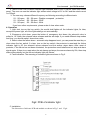
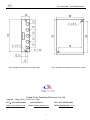
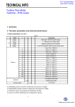
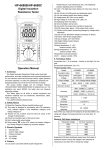
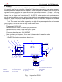
User’s manual for EPC20 module
1. Summary
With advanced flush bonding MPU for the protection module EPC20 for diesel generator set,
it is specially used for the protection of the failure of diesel generating set, in case cause damage to
diesel engine due to misoperation from operator, and so strengthen the reliability and security of the
operation of diesel generator set .When the over low oil pressure of motoroil(<0.1Mpa), over high
oil temperature ( >95℃ ) , over high water temperature and over low water level in water tank
happen, the set alarms and stop running. For the EPC20, adopt epoxide resin module structure
with the whole solidifying structure, and so it is provided with many advantages, such as shockproof,
dampproof, simple connection, reliable performance and so on. At present, our products have been
widely used in mute and ordinary set.
Note: The shared input port is engaged by the high oil temperature protection and low water
level protection, and so the user can only choose one of them.
2. Specification
Power supply: DC 8V~35V
Maximum output current in indicator light port: 300mA
Maximum output current in stop control port: 300mA
Maximum output current in alarm output port: 3A
Frequency detecting signal: 80V~300V AC
Note: the alarm port is optional, if you need it, please make it clear when order.
3. Connection
1. The EPC20 electric connection is shown in fig 1.
5
4
2
3
1
Frequency Signal
(80-300V)
L
L
6
EPC20
K
S0
OT
S2
OP
BR
RB
SR-
9
1
11
SR+
L+
L1
L2
L3
L4
12
K
L5
2
1
2
3
4
5
6
8
S1
WT
SB
7
N
N
+
1
2
3
4
5
6
10
1. EPC20 Module
2- Key Switch
3- Water Temperature Alarm Sensor
4- Oil Temperature Alarm Sensor
5- Battery
6- Stop Solenoid Valve
7- Oil Pressure Alarm Sensor
8- Reset Button
9- Stop Button
10- Pilot Lamp
11- Stop Relay
12- Alarm
Fig 1 Diagram for EPC20
-1-
User’s manual for EPC20 module
2. There is one PCB of failure indicator light attached with EPC20, it can be fixed onto control
panel. The user can use the indicator light whose rated voltage is12V or 24V and the rated current
is <300mA.
3. The user may choose different frequency as following according to different sets
S1、S0 open, S2、S0 open : Disable overspeed protection
S1、S0 short, S2、S0 open : 55HZ
S1、S0 open, S2、S0 short : 66Hz
If you have other requirements, please make it clear when order.
4. Operation
1. Light test: turn-on the key switch, the mould shall lighten all the indicator lights, 2s later,
except the power light, all of the lights shall go out automatically.
2. Emergency shut down: press the button of emergency shut down, the solenoid valve is
pulled in, 10 s later, the solenoid valve releases and the set stops. If you need different stop modes
and time, you should make it clear when order.
3. Reset: when the failure alarm、automatic stop happens to set, you can press the reset key or
close down the key switch, 2 s later, turn on the key switch, the protector is reset and the failure
indicator light is off, the solenoid valves releases and the warner stops alarm. After reset of
protector, if the failure has not been eliminated, the protection mould shall send out stop and alarm
signal again. If there is no reset when the set alarms and stops, the warner alarms by 25s, then stop
alarm automatically, but the failure indicator light still flickers.
4. Fault indication: The meaning of indicator lights are shown in Fig 2.
Fig2. PCB of indicator light
5. Installation
The dimension of indicator PCB and module are shown in Fig 3. and
-2-
Fig 4.
User’s manual for EPC20 module
Fig3. Outside measurement of indicator light
Fig4. Outside measurement of protection mould
Fujian Fu'an Deepblue Electronic Co.,Ltd.
Address:Jiang Jia Du, Fu’an City, Fujian
TEL:0593-6563990-801
http://www.smartcon.cn
(0)13515066128
FAX: 0593-6563990-808
Email: [email protected]
-3-
MSN:[email protected]