1
User Manual
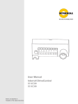
Interroll DriveControl
DC-EC100
Manufacturer
Interroll Engineering GmbH
Höferhof 16
D-42929 Wermelskirchen
Tel. +49 2193 230
Fax. +49 2193 2022
www.interroll.com
Copyright
The copyright of this manual remains with Interroll Corporation. This manual
includes regulations and technical drawings which may not be copied or
duplicated either in whole or in part. Unauthorized use, publication, or application
of this document is prohibited.
Version 1.2 (02/2009) en
Original language
DriveControl DC-EC100
Table of contents
Introduction
Table of contents
Handling of the user manual . . . . . . . . . . . . . . . . . . . . . . . . . . . . . . . . . . . . 2
Warnings in this manual . . . . . . . . . . . . . . . . . . . . . . . . . . . . . . . . . . . . . . . 2
Further symbols . . . . . . . . . . . . . . . . . . . . . . . . . . . . . . . . . . . . . . . . . . . . . 3
Safety
General safety instructions
Intended use . . . . . . . . . . .
Unintended use . . . . . . . . .
Qualified persons . . . . . . .
Risks . . . . . . . . . . . . . . . . .
Interfaces . . . . . . . . . . . . .
.
.
.
.
.
.
.
.
.
.
.
.
.
.
.
.
.
.
.
.
.
.
.
.
.
.
.
.
.
.
.
.
.
.
.
.
.
.
.
.
.
.
.
.
.
.
.
.
.
.
.
.
.
.
.
.
.
.
.
.
.
.
.
.
.
.
.
.
.
.
.
.
.
.
.
.
.
.
.
.
.
.
.
.
.
.
.
.
.
.
.
.
.
.
.
.
.
.
.
.
.
.
.
.
.
.
.
.
.
.
.
.
.
.
.
.
.
.
.
.
.
.
.
.
.
.
.
.
.
.
.
.
.
.
.
.
.
.
.
.
.
.
.
.
.
.
.
.
.
.
.
.
.
.
.
.
.
.
.
.
.
.
.
.
.
.
.
.
.
.
.
.
.
.
.
.
.
.
.
.
.
.
.
.
.
.
.
.
.
.
.
.
.
.
.
.
.
.
.
.
.
.
.
.
.
.
.
.
.
.
.
.
.
.
.
.
.
.
.
.
.
.
4
4
4
5
5
5
Components . . . . . . . . . . . . . . .
Dimensions . . . . . . . . . . . . . . . .
Product description . . . . . . . . . .
Incline and decline applications.
Inputs and outputs . . . . . . . . . .
DIP switches . . . . . . . . . . . . . . .
Meaning of the LEDs. . . . . . . . .
DriveControl label . . . . . . . . . . .
Technical data. . . . . . . . . . . . . .
Speed settings . . . . . . . . . . . . .
Wiring diagrams . . . . . . . . . . . .
.
.
.
.
.
.
.
.
.
.
.
.
.
.
.
.
.
.
.
.
.
.
.
.
.
.
.
.
.
.
.
.
.
.
.
.
.
.
.
.
.
.
.
.
.
.
.
.
.
.
.
.
.
.
.
.
.
.
.
.
.
.
.
.
.
.
.
.
.
.
.
.
.
.
.
.
.
.
.
.
.
.
.
.
.
.
.
.
.
.
.
.
.
.
.
.
.
.
.
.
.
.
.
.
.
.
.
.
.
.
.
.
.
.
.
.
.
.
.
.
.
.
.
.
.
.
.
.
.
.
.
.
.
.
.
.
.
.
.
.
.
.
.
.
.
.
.
.
.
.
.
.
.
.
.
.
.
.
.
.
.
.
.
.
.
.
.
.
.
.
.
.
.
.
.
.
.
.
.
.
.
.
.
.
.
.
.
.
.
.
.
.
.
.
.
.
.
.
.
.
.
.
.
.
.
.
.
.
.
.
.
.
.
.
.
.
.
.
.
.
.
.
.
.
.
.
.
.
.
.
.
.
.
.
.
.
.
.
.
.
.
.
.
.
.
.
.
.
.
.
.
.
.
.
.
.
.
.
.
.
.
.
.
.
.
.
.
.
.
.
.
.
.
.
.
.
.
.
.
.
.
.
.
.
.
.
.
.
.
.
.
.
.
.
.
.
.
.
.
.
.
.
.
.
.
.
.
.
.
.
.
.
.
.
.
.
.
.
.
.
.
.
.
.
.
.
.
.
.
.
.
.
.
.
.
.
.
.
.
.
.
.
.
.
.
.
.
.
.
.
.
.
. 6
. 7
. 8
. 8
. 9
10
11
12
12
13
15
Product information
Transport and storage
Transport . . . . . . . . . . . . . . . . . . . . . . . . . . . . . . . . . . . . . . . . . . . . . . . . . 16
Storage . . . . . . . . . . . . . . . . . . . . . . . . . . . . . . . . . . . . . . . . . . . . . . . . . . . 16
Assembly
Warning notices concerning assembly . . . . . . . . . . .
Warning notices concerning the electrical installation
Installing the DC-EC100 in a conveyor system . . . . .
Electrically installation . . . . . . . . . . . . . . . . . . . . . . . .
.
.
.
.
.
.
.
.
...
...
...
...
....
....
....
....
...
...
...
...
....
....
....
....
17
17
18
18
Initial startup and operation
Initial startup . . . . . . . . . . . . . . . . . . . . . . . . . . . . . . . . . . . . . . . . . . . . . . . 19
Operation . . . . . . . . . . . . . . . . . . . . . . . . . . . . . . . . . . . . . . . . . . . . . . . . . 19
Maintenance and cleaning
Warnings concerning maintenance and cleaning. . . . . . . . . . . . . . . . . . . . 20
Maintenance . . . . . . . . . . . . . . . . . . . . . . . . . . . . . . . . . . . . . . . . . . . . . . . 20
Cleaning . . . . . . . . . . . . . . . . . . . . . . . . . . . . . . . . . . . . . . . . . . . . . . . . . . 20
Troubleshooting
Error search . . . . . . . . . . . . . . . . . . . . . . . . . . . . . . . . . . . . . . . . . . . . . . . 21
Abandonment and disposal
Abandonment . . . . . . . . . . . . . . . . . . . . . . . . . . . . . . . . . . . . . . . . . . . . . . 22
Disposal . . . . . . . . . . . . . . . . . . . . . . . . . . . . . . . . . . . . . . . . . . . . . . . . . . 22
Appendix
Accessories . . . . . . . . . . . . . . . . . . . . . . . . . . . . . . . . . . . . . . . . . . . . . . . 23
Glossary . . . . . . . . . . . . . . . . . . . . . . . . . . . . . . . . . . . . . . . . . . . . . . . . . . 24
Manufacturer's declaration . . . . . . . . . . . . . . . . . . . . . . . . . . . . . . . . . . . . 25
Version 1.2 (02/2009) en
Original language
1
DriveControl DC-EC100
Introduction
Handling of the user manual
Introduction
Content of the manual
This manual contains important advice, notes, and information about the
DC-EC100 in all phases of its lifecycle:
• Transport, assembly, and commissioning
• Safe operation, maintenance, troubleshooting, and disposal
• Accessories
Validity of the manual
The manual describes the DC-EC100 as it is delivered by Interroll.
Special application designs require validation from Interroll and additional
technical instructions.
This manual is part of the
product
For trouble-free, safe operation and warranty claims, read this manual and
follow the instructions before handling the DC-EC100.
Keep this manual near to the DC-EC100.
Pass this manual on to any subsequent operator or occupant of the
DC-EC100.
Interroll does not accept any liability for malfunctions or defects due to nonobservance of this manual.
If you have any questions after reading this user manual, feel free to contact
our customer service. See the last page for contact information.
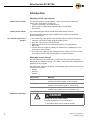
Warnings in this manual
The warnings in this document refer to risks which may arise while using the
DC-EC100. For relevant warnings, see "Safety", page 4 and the warnings at the
beginning of each chapter.
There are three categories of danger. The following signal words are used in the
document as required:
• Danger
• Warning
• Caution
Signal word
Meaning
Danger
Indicates a hazardous situation which, if not
avoided, will result in death or serious injury.
Warning
Indicates a hazardous situation which, if not
avoided, could result in death or serious injury.
Caution
Indicates a hazardous situation which, if not
avoided, may result in minor or moderate injury.
Structure of warnings
DANGER
Nature and source of the hazard
Possible consequence of non-observance
Information about how to avoid the hazard.
2
Version 1.2 (02/2009) en
Original language
DriveControl DC-EC100
Introduction
Further symbols
This symbol identifies possible material damage.
Information about how to avoid damage.
Important
This symbol displays safety instructions.
Hint
This symbol marks useful and important information.
This symbol marks the steps that have to be carried out.
Version 1.2 (02/2009) en
Original language
3
DriveControl DC-EC100
Safety
General safety instructions
Safety
The DC-EC100 is designed according to the technical state of the art and is
reliable in operation, once distributed. However, risks may still arise.
• Risks of physical injury to the user or bystanders.
• Adverse effects of the DriveControl and other material.
Important
Disregarding the warnings in this manual may lead to serious injury.
Always read the entire operating and safety instructions before starting to
work with the DriveControl and follow the information contained herein in full.
Only instructed and qualified persons may work with the DriveControl.
Always keep this user manual at hand when working on the DriveControl so
that you can consult it quickly if required.
Always comply with relevant national safety regulations.
If you have any questions after reading this user manual, feel free to contact
our customer service. See the last page for contact information.
Intended use
The DC-EC100 may only be used for industrial applications and in an industrial
environment to control a RollerDrive EC100. It must be integrated in a conveyor
module or a conveying system. Any other use is considered inappropriate.
Use of the DC-EC100 is only allowed in the areas described under product
information.
Any changes that affect the safety of the product are not allowed.
The DC-EC100 may only be used within the given operation limits.
Unintended use
Applications not according to the intended use of the DC-EC100 require approval
from Interroll.
4
Version 1.2 (02/2009) en
Original language
DriveControl DC-EC100
Safety
Qualified persons
Qualified persons are persons who read and understand the manual and, taking
national regulations into account, can competently execute incidental work.
Only instructed and qualified persons may work with the DriveControl, taking the
following into account:
• the relevant manuals and diagrams,
• the warning and safety instructions in this manual,
• the system specific regulations and requirements,
• national or local regulations and requirements for safety and accident
prevention.
Risks
Important
The following list informs you about the various types of danger or damage that
may occur while working with the DC-EC100.
Persons
Electricity
Working environment
Avoiding malfunctions in
operation
Maintenance
Maintenance or repair work must only be executed by authorized and qualified
persons in accordance with the applicable regulations.
Before using the DriveControl, ensure that no unauthorized persons are near
the conveyor.
Only perform installation and maintenance work after you have switched off
the power. Ensure that the power cannot be turned on accidentally.
Do not use the DriveControl in explosive atmospheres.
Remove equipment or material which is not required from the workspace.
Regularly check the DriveControl for visible damage.
In case of fumes, turn off the power at once and ensure that it cannot be
turned on accidentally.
Contact qualified personnel immediately to find the source the malfunction.
As the product is maintenance free, you only need to check regularly for
visible damage and that all leads and screws are still tightened.
Interfaces
By assembling the DriveControl in a conveyor module, potential hazards may
occur. These are not described in this manual and have to be analyzed during the
design, installation, and startup of the conveyor module.
After assembling the DriveControl in a conveyor module, check the whole
system for any new potential dangerous condition prior to turning on the
conveyor.
Version 1.2 (02/2009) en
Original language
5
DriveControl DC-EC100
Product information
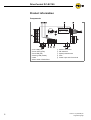
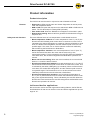
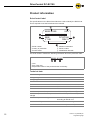
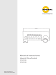
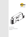
Components
Product information
05052 01925
8996
V 1.00
1
2
3
4
5
6
6
Fuse LED (red)
Power LED (green)
Fault LED (red)
Warning LED (amber)
Label
Motor cable of RollerDrive
7
8
9
bl
bm
USA
DC-EC100
REV: 0
Sensor connection
DIP switches
Speed potentiometer
Fuse
Power input and I/O terminal
Version 1.2 (02/2009) en
Original language
DriveControl DC-EC100
Product information
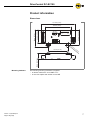
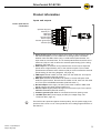
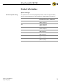
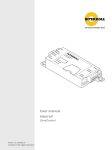
Dimensions
137 mm (5.4 in)
102 mm (4.0 in)
8996
V 1.00
USA
62 mm (2.44 in)
54 mm (2.0 in)
69 mm (2.7 in)
05052 01925
DC-EC100
REV: 0
ø
5.
6
m
m
(0
.2
2
in)
22 mm (0.87 in)
79 mm (3.1 in)
Mounting hardware
Version 1.2 (02/2009) en
Original language
The following mounting hardware is supplied:
• 2x button head screw 10-32 UNF x 0.5"
• 2x nut with captive star washer 10-32 UNF
7
DriveControl DC-EC100
Product information
Product description
The DC-EC100 must be used in conjunction with a RollerDrive EC100.
Features
•
•
•
•
Safety and stall functions
Diagnostics: LEDs provide motor and sensor diagnostics as well as power,
fuse, and temperature status.
NPN or PNP: All inputs and outputs can be switched for NPN or PNP with one
switch. The "No fault output" is always PNP (fail-safe).
Zero motion hold: When the RollerDrive is stopped, it will be held in place.
Regenerative braking: Motor acts like a generator and feeds back energy to
the power bus.
There are different levels of over-temperature or stall-related functions:
• Motor temperature foldback: At a motor temperature of 80 °C (176 °F) the
DriveControl will fold back peak current down to continuous current. This is
indicated by the amber LED lighting up constantly. When the RollerDrive cools
down, the amber LED extinguishes, and the maximum peak current is now
possible again. The motor can run at this reduced current limit indefinitely
without harming the DriveControl or RollerDrive.
• Motor temperature shutdown: At a motor temperature of 100 °C (212 °F)
the DC-EC100 will shut down the motor and the motor will go into
regenerative braking. This is indicated by the red LED. When the RollerDrive
cools back down, the red LED extinguishes and RollerDrive operation will
resume.
• Motor stall current limiting: When the motor is stalled, the current will fold
back to 1.4 A until the stall is cleared.
• DriveControl temperature foldback: At a card temperature of 70 °C (158 °F)
the DriveControl will fold back peak current down to continuous current. This
is indicated by the amber LED lighting up constantly. When the DriveControl
cools down, the amber LED extinguishes, and the maximum peak current is
now possible again. The DriveControl can run at this reduced current limit
indefinitely without harm to the DriveControl or RollerDrive.
• DriveControl temperature shutdown: At a DriveControl temperature of
90 °C (194 °F) the DriveControl will shut down the RollerDrive and the motor
will go into regenerative braking. This is indicated by the red LED. When the
DriveControl cools back down the red LED extinguishes and RollerDrive and
DriveControl operation will resume.
Incline and decline applications
Due to the zero motion hold and regenerative braking features, the DC-EC100
and RollerDrive EC100 can be used for incline and decline applications up to an
angle of 15°.
8
Version 1.2 (02/2009) en
Original language
DriveControl DC-EC100
Product information
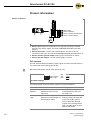
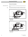
Inputs and outputs
Power input and I/O
connections
Speed analog input
External pot +
FWD input
REV input
No fault output
Sensor output
Common ground input
+24 VDC input
8
7
6
5
4
3
2
1
Speed analog input: External speed control down to approximately 23% of
the maximum speed, if a 0 to 5 VDC PLC or analog input is connected
between here and GND. When using a 10 kΩ external potentiometer, the
wiper must be connected here. The on-board potentiometer should be set to
maximum (CW) so it will not affect the external speed setting (for the wiring
diagrams, see page 15).
External pot+: An external 10 kΩ potentiometer can be used to adjust the
speed down to approximately 23% of the maximum speed. The on-board
potentiometer should be set to maximum (CW) so it will not affect the external
speed setting (for the wiring diagrams, see page 15).
FWD input: Normal rotation is CCW, seen from the cable end. This input is
PNP/NPN selectable (with DIP switch 1).
REV input: Causes the RollerDrive to operate in reverse transport mode
while the signal is active. Normal reverse rotation is CW, seen from the cable
end. This input is PNP/NPN selectable (with DIP switch 1).
No fault output: Active high (+24 VDC) when either in NPN or PNP mode.
Signal goes low only when system faults occur.
Sensor output: Signal passed through from the sensor input. This output is
PNP/NPN selectable (with DIP switch 1).
Common ground input: Must be connected to the main power ground.
+24 VDC input: Main power supply 24 VDC (for voltage range, see
"Technical data", page 12).
Hint
The DC-EC100 is protected against reverse polarity, but the power supply must
provide a short circuit or over current protection and a voltage ripple tolerance of
less than 5%.
Version 1.2 (02/2009) en
Original language
9
DriveControl DC-EC100
Product information
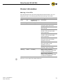
Sensor connection
Sensor input
Sensor fault input
Sensor common ground output
Sensor +24 VDC output
4
3
2
1
Sensor input: Signal from external source, typically a photoeye. Passed
through to the sensor output. This input is PNP/NPN selectable (with DIP
switch 1).
Sensor fault input: If sensor has a fault output for low gain, it can be
connected to this input. This input is PNP/NPN selectable (with DIP switch 1).
Sensor common ground output: Power ground connection for sensor.
Sensor +24 VDC output: +24 VDC power supply for sensor.
DIP switches
The DIP switches allow the selection of the logical convention and the direction.
The default DIP switch settings are all OFF.
Hint
ON
DIP switch settings are read at reset (power-up) only.
SW2: Rotation
SW1: Logic
ON
CW
PNP
OFF
CCW
NPN
DIP switch settings
The following table shows the switch position for different situations:
10
DIP switch
ON (left position)
OFF (right position)
SW2
Rotation
Clockwise (rotation of the
RollerDrive seen from the
cable end)
Counter clockwise (rotation
of the RollerDrive seen from
the cable end)
SW1
Logic
PNP: all external inputs,
photoeye input and output are
active high (24 VDC).
NPN: all external inputs,
photoeye input and output are
active low (0 VDC ground).
This excludes the "No fault
output" which is always active
high (+24 VDC) when in either
NPN or PNP mode.
Version 1.2 (02/2009) en
Original language
DriveControl DC-EC100
Product information
Meaning of the LEDs
The LEDs provide motor and sensor diagnostics as well as power, fuse, and
temperature status. The following table shows the meaning of the LEDs:
LED
Color
Status
Meaning
Fuse
red
on steady (all other
LEDs are off)
Fuse blown
Power
green
on steady
Power OK
Fault
red
on steady
Stalled motor
Low gain signal from sensor
Motor or motor cable
disconnected
Over-voltage detection
29 VDC ± 0.2 VDC (will cease
normal operation)
Under-voltage detection
19 VDC ± 0.2 VDC (will cease
normal operation)
DriveControl severe temperature
shut-down (will cease normal
operation until cool)
Motor severe temperature shutdown (will cease normal
operation until cool)
Low gain or bad sensor (sensor
with fault output connected)
Warning
amber
on steady
Motor current is limited to
maximum continuous current due
to motor over-temperature
Motor current is limited to
maximum continuous current due
to card over-temperature
Hint
There is no error output if the amber LED is on.
Version 1.2 (02/2009) en
Original language
11
DriveControl DC-EC100
Product information
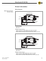
DriveControl label
The specifications on the DriveControl label are used to identify the DC-EC100.
This is required to use the DriveControl as intended.
USA
05052 01925
8996
V 1.00
1
2
3
DC-EC100
REV: 0
Serial number
Country of production
Product name
4
5
6
Revision information
Article number
Identification barcode
The serial number contains the following information about the production date:
05052 01925
1
2
3
Year
Day of the year
Sequential number of the produced units on that day
Technical data
12
Nominal voltage
24 VDC
Voltage range
18 to 28 VDC
Voltage ripple tolerance
< 5%, < 1% recommended
Continuous current
1.8 A
Peak current
4.1 A
Fuse
5 A slow blow Littlefuse 0452005
Protection classification
IP20
Ambient temperature for operation
0 °C to 40 °C (32 °F to 104 °F)
Ambient temperature for transport and
storage
-20 °C to 75 °C (-4 °F to 167 °F)
Ambient temperature changes
max. 1 °K/min; 3 h; two cycles
according to IEC 68-2-14
Ambient humidity
max. 90% not condensing
Installation altitude above sea level
max. 1000 m (max. 3300 ft)
Version 1.2 (02/2009) en
Original language
DriveControl DC-EC100
Product information
Speed settings
On board speed setting
Version 1.2 (02/2009) en
Original language
The speed can be continuously adjusted (between 100% and approximately
33%) by the potentiometer on the DriveControl. Default setting is maximum.
Gear ratio
Speed range
RollerDrive EC100 + DC-EC100
12:1
1.32 to 0.44 m/s
(260 to 87 fpm)
16:1
1.03 to 0.34 m/s
(202 to 67 fpm)
24:1
0.69 to 0.22 m/s
(135 to 45 fpm)
36:1
0.44 to 0.15 m/s
(88 to 29 fpm)
48:1
0.35 to 0.12 m/s
(68 to 22 fpm)
64:1
0.25 to 0.08 m/s
(50 to 17 fpm)
96:1
0.17 to 0.06 m/s
(34 to 11 fpm)
13
DriveControl DC-EC100
Product information
External speed setting
Apart from the potentiometer on the DriveControl, there are other ways to set the
speed.
Hint
When the DIP switch settings ON / OFF are stated, both settings are possible for
the wiring shown (for the meaning of the settings, see "DIP switches", page 10).
External speed set by potentiometer
Direction of travel
Motor cable
Ext. analog speed set
Ext. pot +
Sensor input (NPN/PNP)
Fault (Input)
DC Common (Output)
+24 VDC (Output)
GND (Input)
+24 VDC (Input)
+24 VDC
GND
to ext. analog speed set of
next DriveControl DC-EC100
Potentiometer
10 k Ω
Pot. at minimum equals 23% of rated speed
DIP switch settings:
• SW2: ON / OFF
• SW1: ON / OFF
External speed set by PLC
Direction of travel
Motor cable
Ext. analog speed set
Sensor input (NPN/PNP)
Fault (Input)
GND (input)
DC Common (Output)
+24 VDC (Output)
+24 VDC (input)
+24 VDC
to ext. analog speed set of
next DriveControl DC-EC100
GND
0 - 5 VDC
GND
PLC analog speed output (0 - 5 VDC)
0 V = 23 % of rated speed
5 V = 100 % of rated speed
DIP switch settings:
• SW2: ON / OFF
• SW1: ON / OFF
14
Version 1.2 (02/2009) en
Original language
DriveControl DC-EC100
Product information
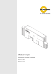
Wiring diagrams
Motor start and external
direction setting
Motor start and external direction setting in PNP mode
Direction of travel
Motor cable
FWD (Input)
REV (Input)
GND (Input)
+24 VDC (Input)
+24 VDC
GND
REV (Input)
FWD (Input)
DIP switch settings:
• SW2: ON / OFF
• SW1: ON
RollerDrive rotation direction:
• FWD connected to 24 VDC at PNP mode causes ccw rotation.
• REV connected to 24 VDC at PNP mode causes cw rotation.
• FWD and REV connected to 24 VDC at PNP mode causes coast mode.
Motor start and external direction setting in NPN mode
Direction of travel
Motor cable
FWD (Input)
REV (Input)
GND (Input)
+24 VDC (Input)
+24 VDC
GND
REV (Input)
FWD (Input)
DIP switch settings:
• SW2: ON / OFF
• SW1: OFF
RollerDrive rotation direction:
• FWD connected to GND at NPN mode causes ccw rotation.
• REV connected to GND at NPN mode causes cw rotation.
• FWD and REV connected to GND at NPN mode causes coast mode.
Version 1.2 (02/2009) en
Original language
15
DriveControl DC-EC100
Transport and storage
Transport
Transport and storage
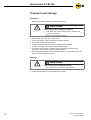
•
Each DriveControl is packed in its own carton case.
CAUTION
Risk of injury due to improper transport
Transport may only be carried out by qualified and
authorized persons.
Observe the following notices.
Do not stack more than four carton boxes.
Check the fixation of the DriveControls before transport.
Avoid hard shocks during transport.
Check each DriveControl visually for damage after transport.
In case of damage, take photos of the damaged parts.
To maintain the warranty, instantly report any damage caused during
transport to the transport company and to Interroll.
Do not transfer the DriveControls between warm and cold environments as
this may cause condensing water.
Storage
CAUTION
Risk of injury due to improper storage
Do not stack more than four carton boxes.
Check each DriveControl for damage after storage.
16
Version 1.2 (02/2009) en
Original language
DriveControl DC-EC100
Assembly
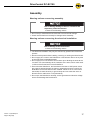
Warning notices concerning assembly
Assembly
Risk of damage leading to failure or shortened life
expectancy of the DriveControl
Observe the following notices.
Do not drop or mishandle the DriveControl to avoid internal damage.
Check each DriveControl visually for damage before assembly.
Warning notices concerning the electrical installation
Risk of damage to the DriveControl
Observe the following notices.
The electrical installation may only be executed by qualified and authorized
persons.
Disconnect the power before installing, removing or rewiring the DriveControl.
Do not apply AC current to the RollerDrive or DriveControl device at any time
as this will cause irreparable damage.
Do not apply too much stress to the connector pins. Bending the wires at the
connector can cause damage to the insulation of the wires, which could result
in failure of the DriveControl or the RollerDrive.
Ensure that the RollerDrive, the DriveControl and the 24 VDC power source
are properly earthed through the frame or supporting structure in which the
RollerDrive and the DriveControl are installed. Failure to do so could cause
the buildup of static electricity or ground loops and can cause the motor or
DriveControl to malfunction or fail prematurely.
Do not spin the RollerDrive manually, as this generates an induction voltage
which could damage the DriveControl.
Version 1.2 (02/2009) en
Original language
17
DriveControl DC-EC100
Assembly
Installing the DC-EC100 in a conveyor system
Use the DriveControl as a template and mark the center of the two mounting
holes. For the distance between the holes, see "Dimensions", page 7.
Drill two ø 5.6 - 6 mm (0.22 - 0.24 in) mounting holes at the marked spots.
Insert the button head screws in the holes on the opposite side the
DriveControl is to be mounted.
Install the DriveControl to the frame with the screws protruding through the
mounting holes.
Slip the nuts to the screws and tighten.
Ensure that there is a ground path between the DriveControl and the conveyor
frame it is mounted to.
Hint
The DriveControl and conveyor frame should be at the same potential referenced
to earth ground.
Electrically installation
The connector supplied with the RollerDrive EC100 mates up with the header on
the DC-EC100.
The connectors "Power input and I/O terminal" and "Sensor connection" are cage
clamp terminals.
To actuate the cage clamp, use the supplied tool or insert a small screwdriver.
Plug in the RollerDrive connector.
18
Version 1.2 (02/2009) en
Original language
DriveControl DC-EC100
Initial startup and operation
Initial startup
Initial startup and operation
Inspections before initial
startup
Ensure that all bolts are tightened according to the specifications.
Ensure that no additional dangerous areas arise due to interfaces with other
components.
Ensure that the wiring is in accordance with specifications and legal
guidelines.
Check all protection devices.
Ensure that no bystanders are in dangerous areas around the conveyor.
Operation
Damage to the DriveControl or the motor of the
RollerDrive due to induction
Do not push items along the roller conveyor by hand.
Do not spin the RollerDrive manually.
Inspections before every
startup
Changing settings
Version 1.2 (02/2009) en
Original language
Check the position of the DIP switches (see "DIP switches", page 10).
Check the speed settings at the speed potentiometer. It is recommended to
run the RollerDrive at maximum speed.
Check the DriveControl for visible damage.
Check all protection devices.
Ensure that no bystanders are in dangerous areas around the conveyor.
Clearly specify and monitor the way goods are placed on the conveyor.
To reduce the speed manually, turn the potentiometer counterclockwise with a
small screwdriver.
To increase the speed manually, turn the potentiometer clockwise with a small
screwdriver.
To set the DIP switches, carefully use a small screwdriver.
19
DriveControl DC-EC100
Maintenance and cleaning
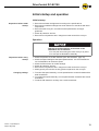
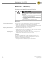
Warnings concerning maintenance and cleaning
Maintenance and cleaning
CAUTION
Risk of injury due to improper handling or accidental
motor starts
Maintenance work and cleaning may only be executed
by qualified and authorized persons.
Only perform maintenance work after switching off the
power. Ensure that the DriveControl cannot be turned
on accidentally.
Set up signs indicating maintenance work.
Maintenance
Checking the DriveControl
The DriveControl must be checked at regular intervals to avoid malfunctions.
Monthly check the DriveControl and its leads for visible damage.
Annually ensure that the screws of the DriveControl are still tight and that the
cables are still laid properly and connected to the terminals.
Replacing the DriveControl
If a DriveControl is damaged, it has to be replaced.
Install a new DriveControl (see "Abandonment", page 22 and see "Installing
the DC-EC100 in a conveyor system", page 18).
Replacing fuse
Carefully use tweezers to remove and insert the fuse. Ensure you do not
damage the fuse holder, the circuit board or its devices.
Cleaning
Dust and dirt in combination with humidity may bridge the electric circuit.
Therefore, in a dirty environment, periodic cleaning will help to avoid shortcircuits which could damage the DriveControl.
Regularly blow off dust and dirt by using low compressed air.
20
Version 1.2 (02/2009) en
Original language
DriveControl DC-EC100
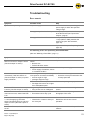
Troubleshooting
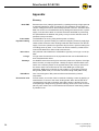
Error search
Troubleshooting
Symptom
Possible cause
Help
System is not operating
No power supply
Check whether the output voltage of the
power supply is within the specified
voltage range.
Wrong polarity of the bus line inputs
Verify the polarity of the bus line inputs
to the DC-EC100 (see "Inputs and
outputs", page 9).
Wrong position of the DIP switch 1
Verify that the position of the DIP switch
1 Logic (NPN or PNP) matches the
sensor type (see "DIP switches",
page 10).
Fuse is blown
Replace the fuse (see "Replacing fuse",
page 20).
The following errors are reported by illuminated LEDs:
(also see "Meaning of the LEDs", page 11)
Symptom
Possible cause
Help
Motor is in brake mode, red fault
LED is on and error output is active
("No fault output" is active).
Invalid state of motor hall effect
sensor
• Broken wire
• Failed hall effect sensor
Replace the RollerDrive.
Voltage over or under limits
• Power supply fluctuations, failure
or overload condition
Check the power supply.
Over voltage detection (caused by
over speed or excessive back EMF)
• decline angle too high
• package weight too high
•
•
Motor overrun, overset speed
• Package enters zone at a higher
than anticipated speed
Reduce the package entry speed.
Red fault LED is on and error output
is active ("No fault output" is active).
Low gain signal from sensor
• Dirty sensor lens or misaligned
Clean the sensor lens and align the
sensor.
Current folds back to maximum
continuous current, amber fault LED
is on.
Card or motor over temperature
• Excessive load or duty cycle
Reduce the load of packages or
throughput of the zone
Current folds back to approximately
1.5 A while applying consistent
torque. Red fault LED is on and error
output is active ("No fault output" is
active).
Motor stall condition
• Obstruction or load too heavy to
be conveyed
Once the stall condition is removed, the
RollerDrive will resume normal
operation.
Red fuse LED is on, all other LED's
are off .
Fuse is blown
Replace fuse and check for possible
reasons.
On a decline, motor is in brake mode
momentarily. Red fault LED is on
("No fault output" is active) or power
supply shutdown.
Version 1.2 (02/2009) en
Original language
Reduce decline angle
At decline conveyors use brake roller
to keep speed low
21
DriveControl DC-EC100
Abandonment and disposal
Abandonment
Abandonment and disposal
CAUTION
Risk of injury due to improper handling
Abandonment may only be executed by qualified and
authorized persons.
Only abandon the DriveControl after switching off the
power. Ensure that the DriveControl cannot be turned
on accidentally.
Disconnect all cables from the DriveControl.
Unscrew the screws attaching the DriveControl to the conveyor frame.
Extract the DriveControl from the conveyor frame.
Disposal
The operator is responsible for the proper disposal of the DriveControl. In doing
so, industry-specific and local provisions must be observed for the disposal of the
DriveControl and its packaging.
22
Version 1.2 (02/2009) en
Original language
DriveControl DC-EC100
Appendix
Accessories
Appendix
DriveControls
Plugs and cables
Part
Part #
Z-Card EC Easy
89Z2
Z-Card EC Full
89Z3
Part
Description
Power and I/O plug
•
•
Sensor plug
•
•
Motor plug
Version 1.2 (02/2009) en
Original language
8-pin cage clamp type connector, Wago part # 231308/026-004
Wire diameter:
– Minimum 0.08 mm2 (AGW 28)
– Maximum 2.5 mm2 (AGW 12)
4-pin cage clamp type connector, Wago part # 734104/000-004
Wire diameter:
– Minimum 0.08 mm2 (AGW 28)
– Maximum 1.5 mm2 (AGW 14)
•
The motor plug for the RollerDrive consists of a plug
and terminal pins
– Plug: AMP part # 175778-8
– Terminal pins: AMP part # 1-175102-1
•
Crimping tool AMP part # 9184381
23
DriveControl DC-EC100
Appendix
Glossary
Back EMF
Coast mode
Dynamic braking
Idler rollers
O-rings
Photoeye
RollerDrive
Zero motion hold
24
Electromotive force (voltage) generated by a package arriving at high speed at
a powered RollerDrive under no load prior to the package’s arrival. EMF is a
counter-voltage phenomenon that is always present in a motor. Excessive back
EMF can cause a current backlash that may damage the DriveControl or power
supply. Care should be taken to minimize excessive back EMF by minimizing
the speed differences between the gravity conveyor and/or different zones of
powered conveyor sections.
The RollerDrive is running freely without power or braking.
For DC motors, dynamic braking is a method of stopping a motor by applying a
resistive load across the motor winding leads after disconnection from the DC
supply. The motor operates as a generator. By its nature, dynamic braking has
no holding power by itself, i.e. the motor can still be rotated by outside forces.
Interroll has added zero motion hold to achieve this.
Non-powered rollers attached to a RollerDrive typically via O-rings or multi-rip
belts.
O-rings made of materials such as polyurethane that connect RollerDrives to
their associated idler rollers.
An ON/OFF sensor that uses light to sense the presence of objects. If the light
beam is broken, an object is present. Usually the light is reflected back to the
sensor via a reflector placed on the opposite side of the conveyor frame from
the sensor itself. The DC-EC100 can use either NPN type or PNP type
photoeyes. NPN sensors indicate an active state by a grounded connection
being made (NPN mode) or a 24 VDC connection being made (PNP mode).
One of several types of DC powered rollers manufactured by Interroll
Corporation.
For DC motors, zero motion hold is a method of holding a motor by applying a
small amount of current to the motor winding leads. When the DC-EC100 is
commanded to stop and accumulate, the braking action is twofold. First, the
motor/package is stopped using dynamic braking. Second, the motor is held in
place by zero motion hold. In this state the DC-EC100 will resist being rotated
by outside forces.
Version 1.2 (02/2009) en
Original language
DriveControl DC-EC100
Appendix
Manufacturer's declaration
in terms of the EC-Machine Directive 98/37/EC and its amendment 98/79/EC,
Annex II B
The manufacturer:
Interroll Engineering GmbH
Höferhof 16
D - 42929 Wermelskirchen
Germany
hereby declares with sole responsibility that the product range
•
DC-EC100
is not a ready-to-use assembly in terms of the EC-Machine Directive and
therefore does not fully comply with the requirements of this directive. It
must not be put into service until the machinery into which it is to be
incorporated has been declared to conform with the provisions of the
Machine Directive.
Applied EC Directives:
Machine Directive 98/37/EC and its amendment 98/79/EC
Low Voltage Directive 2006/95/EC
EMC Directive 2004/108/EC
RoHS Directive 2002/95/EC
Applied harmonized norms:
EN ISO 12100 Part1 and Part2
Wermelskirchen, November 7th 2007
Armin Lindholm
(Managing Director)
(This declaration can be obtained at www.interroll.com, if needed.)
Version 1.2 (02/2009) en
Original language
25
Europe/Nordic
Denmark
Interroll Nordic A/S
Hammerholmen 2-6
DK-2650 Hvidovre/Denmark
Tel. +45 36 88 33 33
Fax +45 36 88 33 72
[email protected]
Interroll Service
Islandsvej 5
DK-7900 Nykøbing M.
Tel. +45 97 71 15 55
Fax +45 97 71 16 55
[email protected]
Iceland
IBH ehf
Dugguvogur 10
104 Reykjavik
Iceland
Tel. +354 562 6858
Fax +354 562 6862
[email protected]
Finland
Tel. +358 9 54 94 94 00
Fax +358 9 54 94 94 16
Norway
Tel. +47 32 88 26 00
Fax +47 32 88 26 10
Sweden
Tel. +46 35 227077
Fax +46 35 227078
United Kingdom
Interroll Ltd.
Brunel Road
Earlstrees Industrial Estate
GB-Corby, Northants NN17 4UX
Tel. +44 1536 200 322
Fax +44 1536 748 515
[email protected]
Germany
Interroll Fördertechnik GmbH
Höferhof 16
D-42929 Wermelskirchen
Tel. +49 2193 23 0
Fax +49 2193 20 22
[email protected]
Austria
Tel. +49 2193 23 187
Fax +49 2193 23 164
Belgium
Tel. +49 2193 23 131
Fax +49 2193 23 164
Italy
Rulli Rulmeca S.p.A.
Via A. Toscanini, 1
I-24011 Almè (Bg)
Tel. +39 035 4300111
Fax +39 035 545523
[email protected]
Portugal
Rulmeca Interroll de Portugal Lda
Apartado 69, Centro Civico
P-6201-909 Covilhã
Tel. +351 275 330 780
Fax +351 275 990 789
[email protected]
Israel
Interroll (Suzhou) Co. Ltd.
Unit 10B, Modern Industrial Square
No. 333 Xing Pu Road
Suzhou Industrial Park
Suzhou, Jiangsu Province
People’s Republic of China
Postal Code: 215126
Tel. +86 512 6256 0383
Fax +86 512 6256 0385
[email protected]
ComTrans-Tech Ltd.
P.O.B. 17433
Tel-Aviv 61174
Israel
Tel. +972 54 4 27 27 47
Fax +972 3 7 44 08 64
[email protected]
Africa
South Africa
Interroll SA Pty. Ltd.
P.O. Box 327
Isando 1600
37 Director Road, Spartan Ext 2
1619
South Africa
Tel. +27 11 281 9900
Fax +27 11 252 9083
[email protected]
North & South America
Luxembourg
USA
Tel. +49 2193 23 190
Fax +49 2193 23 164
Interroll Corporation
3000 Corporate Drive
USA-Wilmington, NC 28405
Tel. +1 910 799 11 00
Fax +1 910 392 38 22
[email protected]
Netherlands
Tel. +49 2193 23 151
Fax +49 2193 23 164
Switzerland
Tel. +49 2193 23 190
Fax +49 2193 23 164
Eastern Europe
Interroll S.A.S.
ZI de Kerannou
B.P. 34
F-29250 Saint Pol de Léon
Tel. +33 298 24 41 00
Fax +33 298 24 41 02
[email protected]
Asia
Central Europe
Western/Southern Europe
France
Near East
Czech Republic
Interroll CZ, s.r.o.
Na Řádku 7/3172
CZ-69002 Břeclav
Tel. +420 519 330 210
Fax +420 519 330 211
[email protected]
Hungary
Tel. +36 23 337 891
Fax +36 23 337 892
Canada
Interroll Components Canada Ltd.
8900 Keele Street
Unit 2 & 3
Concord, Ontario L4K 2N2
Canada
Tel. +1 905 660 4426
Fax +1 905 660 4159
[email protected]
Interroll Canada Ltd.
Drives & Rollers Canada
1201 Gorham Street
Newmarket Ontario L3Y 8Y2
Canada
Tel. +1 905 727 3399
Fax +1 905 727 3299
[email protected]
Poland
Interroll Polska Sp. z o.o.
ul. Płochocińska 85
PL-03-044 Warszawa
Tel. +48 22 741 741 0
Fax +48 22 741 741 1
[email protected]
Slovakia
Tel. +421 2 4363 8102
Fax +421 2 4342 7294
Spain
Slovenia
Interroll España S.A.
Parc Teconològic del Vallès
C/Dels Argenters, 5
Edificio 1, módulos Bp y Cp
E-08290 Cerdanyola del Vallès
Tel. +34 90 211 0860
Fax +34 93 586 4895
[email protected]
Tel. +386 1 56 56 370
Fax +386 1 56 56 372
Turkey
Rol-er Makina San. Ve. Tic. Ltd. Sti.
Pembegul Sok., Dostlar Apt.
No. 12 D. 10 Suadiye
347 40 Istanbul
Turkiye
Tel. +90 216 386 37 75
Fax +90 216 386 38 22
[email protected]
Brasil
Interroll Logistica
Elementos para Sistemas
Transportadores Ltda.
Av. Alexandrina das Chagas
Moreira 945
Bairro Distrito Industrial
Pindamonhangaba-SP
Brasil
CEP 12412 - 800
Tel. +55 12 3648 8021
Fax +55 12 3648 8164
[email protected]
For other countries in
South America, please contact:
Interroll España S.A.
Parc Teconològic del Vallès
C/Dels Argenters, 5
Edificio 1, módulos Bp y Cp
E-08290 Cerdanyola del Vallès
Tel. +34 90 211 0860
Fax +34 93 586 4895
[email protected]
China
Japan
Interroll Japan Co. Ltd.
302-1 Shimokuzawa
Sagamihara-shi
Kanagawa 229-1134
Japan
Tel. +81 42 764 2677
Fax +81 42 764 2678
[email protected]
Korea
Interroll Korea Corporation
Room 301, Dongsan Bldg, 333-60
Shindang-Dong, Choong-ku
Seoul
Korea
Tel. +822 2 231 1900
Fax +822 2 254 36 83
[email protected]
Singapore
Interroll (Asia) Pte. Ltd.
386 Jalan Ibrahim
629156 Singapore
Republic of Singapore
Tel. +65 6266 6322
Fax +65 6266 6849
[email protected]
Thailand
Interroll (Thailand) Co. Ltd.
41/6 Moo 6, Bangchalong,
Bangplee
Samutprakarn 10540
Thailand
Tel. +66 2 337 0188 91
Fax +66 2 337 01 92
[email protected]
India
Interroll Drives and Rollers India Private Limited
SF 12, KSSIDC Building 3rd Stage
Peenya, Bangalore
Bangalore - 560058
Kamataka, India
Tel. +91 80 2359 5904
Fax +91 80 2349 5241
[email protected]
Australia & New Zealand
Australia
Conveyor Solutions Australia Pty. Ltd.
70 Keon Parade
Thomastown
VIC 3073
Australia
Tel. +61 3 9460 2155
Fax +61 3 9460 2029
[email protected]
New Zealand
Automation Equipment (NZ) Ltd.
45 Colombo Street
Frankton
Hamilton
New Zealand
Tel. +64 7847 2082
Fax +64 7847 7160
[email protected]
For other countries please
see contacts at
www.interroll.com
Version 1.2 (02/2009) en
Original language