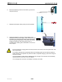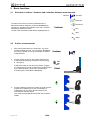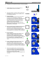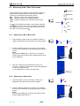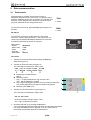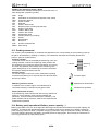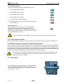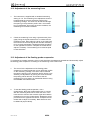
1
Dear customer, congratulations for your choice, a Trimos measuring instrument. Over more than 30 years,
our products have built up an excellent reputation in terms of quality, accuracy and longevity. In order to get
also an entire satisfaction of the present product, we recommend to read carefully this user’s manual.
Version 1.2 / 2002-08
User’s manual
TRIMOS SA
Av. de Longemalle 5
Tel ++ 41 21 633 01 01
Fax ++41 21 633 01 02
750 50 0001 03
1/28
CH 1020 Renens
[email protected]
Switzerland
www.trimos.ch
Contents
Safety regulations..............................................................................................................................3
1.1
Important information....................................................................................................................3
1.2
Symbols used ...............................................................................................................................3
1.3
General warnings..........................................................................................................................3
2 Instrument description ......................................................................................................................4
2.1
Instrument construction.................................................................................................................5
2.2
Handwheel for measuring carriage displacement and probing (manual version)............................5
2.3
Display unit ...................................................................................................................................5
2.4
Interfaces/connectors....................................................................................................................5
3 Getting started ...................................................................................................................................6
3.1
Packing list ...................................................................................................................................6
3.2
Setting up .....................................................................................................................................7
4 Getting started ...................................................................................................................................9
4.1
Setting into operation ....................................................................................................................9
5 Basic functions ................................................................................................................................10
5.1
Selection of surface / diameter and centerline distance measurements.......................................10
5.2
Surface measurements...............................................................................................................10
5.3
Diameter and centerline distance measurements........................................................................11
6 Secondary functions .......................................................................................................................12
6.1
References .................................................................................................................................12
6.2
Selection of the resolution...........................................................................................................12
6.3
Setting / memorizing of the probe constant .................................................................................12
6.4
Selection of the measuring unit: mm/inch ...................................................................................12
6.5
Measuring in Min / Max / Delta mode..........................................................................................13
6.6
Zero setting of the display ...........................................................................................................14
6.7
Checking of squareness deviation...............................................................................................14
6.8
Angle measurements ..................................................................................................................16
6.9
Difference between 2 measurements ..........................................................................................17
6.10
Tolerance limits mode .............................................................................................................17
6.11
Complete clearing of the buffer ...............................................................................................18
6.12
Clearing of the last displayed value in the buffer......................................................................18
7 Programmable function keys ..........................................................................................................19
8 Configuration (Set-up).....................................................................................................................19
9 Data communication........................................................................................................................21
9.1
Data transfer...............................................................................................................................21
10
Application and adjustments .......................................................................................................22
10.1
Application of the manual and the motorized handwheel .........................................................22
10.2
Display ....................................................................................................................................22
10.3
Probing movement ..................................................................................................................23
10.4
Battery pack (operational lifetime, power capacity…)...............................................................23
10.5
Test of luminous LED's............................................................................................................24
10.6
Measurement with / without air cushion displacement..............................................................24
10.7
Reset mode.............................................................................................................................24
10.8
Adjustment of the measuring force ..........................................................................................25
10.9
Adjustment of the floating probe suspension............................................................................25
10.10 Position of the measuring insert in the holder .........................................................................26
10.11 Replacing the battery pack ......................................................................................................26
10.12 Temperature variations............................................................................................................27
11
Maintenance ..................................................................................................................................27
11.1
Cleaning..................................................................................................................................27
12
Technical specifications...............................................................................................................27
13
After sales service.........................................................................................................................27
13.1
Complaints / repairs.................................................................................................................27
13.2
Agents.....................................................................................................................................27
14
Declaration of conformity.............................................................................................................28
1
750 50 0001 03
2/28
1 Safety regulations
1.1
Important information
In order to prevent any damages due to a wrong manipulation, please read carefully the following
instructions. TRIMOS will not assume any responsibility in case of damages caused by inadequate use
which is not in line with the present manual.
1.2
Symbols used
The following symbols are used in this manual :
General warning, utilization advices
Risk of electric shock
Electrostatic protection
1.3
General warnings
Protection against electrostatic interferences:
The static electricity can damage the electronic components of the instrument. In order to
prevent this type of damages, avoid any contact with the connector pins.
Switch on the power supply :
The instrument should be switched on only when the electrical connections have been
completed correctly.
In order to prevent any changes of the instrument performance or any accident, the instrument
should never be dismounted.
The electronic display unit incorporates high voltage components. If, for any reason, the
electronic unit needs to be opened, only authorized personnel is allowed to do it.
Do not expose the instrument, its components and accessories to rain or any projection of
fluids. Avoid penetration of foreign substances into the connectors and the instrument
openings.
In case of problems with the instrument or any of its parts (no display, overheating, anomalous
smell, ..), switch off the instrument immediately and disconnect the power supply. Please
contact your local TRIMOS agent.
This is a high accuracy instrument. Particular care should be taken during its entire operational
lifetime. Care mainly about the following specific points:
- Use the instrument on a stable, smooth and clean surface plate.
- Avoid any shock to prevent the characteristic features of the instrument from loosing its
performances.
- Use the instrument in a vibration free area.
- Avoid the exposure to direct sunlight and excessive humidity.
- Avoid the proximity of heating or air conditioning systems.
- Respect the indicated environmental conditions.
750 50 0001 03
3/28
2 Instrument description
37 36 35 34 33
1
2
32
31
2.4
29
30
28
3
4
27
5
26
6
25
7
2.3
24
8
23
18
19 20 21 22
17
16
2.2
14
13
15
2.1
9
750 50 0001 03
10
4/28
11
12
2.1
Instrument construction
1.
2.
3.
4.
5.
6.
7.
8.
9.
10.
11.
12.
13.
14.
2.2
Column
Upper measuring insert holder
Screw for the adjustment of the floating probe suspension
Transport safety screw for locking of the probe suspension (chromium plated)
Lever for fast displacement of the measuring carriage (only on manual version)
Screw for the measuring force adjustment
Lower measuring insert holder
Measuring insert
Base with air cushion system for instrument displacement
Operating handle for the displacement of the instrument
Press button to activate the air cushion
Programmable function keys
Handwheel for measuring carriage displacement and probing movement (motorized version)
Display unit (see details here-after)
Handwheel for measuring carriage displacement and probing (manual version)
15. Handwheel for measuring carriage displacement and probing movement (manual version)
16. Locking device to activate the fine adjustment
17. Fine adjustment screw
2.3
Display unit
18.
19.
20.
21.
22.
23.
24.
25.
26.
27.
28.
2.4
Selection of references / numeric display of 7 / alphanumeric display of a b c
Selection of resolution / numeric display of 8 / alphanumeric display of d e f
Storage of probe constant / numeric display of 9 / alphanumeric display of g h i
Selection of measuring unit (mm/inch) / numeric display of 4 / alphanumeric display of j k l
Min, max or delta mode/ numeric display of 5 / alphanumeric display of m n o
Zero setting of the display / numeric display of 6 / alphanumeric display of p q r
Squareness deviation checking / numeric display of 1 / alphanumeric display of s t u
Angle measurements / numeric display of 2 / alphanumeric display of v w x
Selection of the calculation mode / numeric display of 3 / alphanumeric display of y z
Selection of the tolerance limits mode / numeric display of 0
Complete clearing of the buffer / decimal point display
Clears the last value stored in the buffer / change of sign
Sets the display to the previously input preset value of the current reference
Print-out of data
Confirmation of selected or input data
Selection of main functions
Displacement of the cursor to the previous field
Displacement of the cursor to the following field
On/Off key (power ON / OFF)
Probe setting direction indicator
Green light : measurement in specified tolerances
Red light : measurement out of specified tolerances
Orange light: measurement out of specified tolerance, but the part can be retouched.
Menu of functions
Display (touch screen for models Vectra-Touch and Mestra-Touch)
Interfaces/connectors
29.
30.
31.
32.
33.
34.
35.
36.
37.
750 50 0001 03
X axis (electronic probe for checking of squareness deviation, horizontal)
Z axis(vertical)
"Instrument" connector
RS 232 male
RS 232 female
AC adaptor connection
USB A
USB B
Foot pedal connection
5/28
3 Getting started
3.1
Packing list
The standard supply of the instrument includes the following items:
1.
Instrument
2.
Display unit
3.
Ac adaptor
4.
Power supply cable
5.
Measuring insert, tungsten carbide ball, ∅ 4 mm
6.
Setting gauge
7.
Protection cover
8.
Allan key 2 mm
9.
Allen key 5 mm
10. 2 screws (to fix the display unit)
11. User’s manual
12. Electric connexion diagram
13. Test certificate
14. Certificate of guarantee
When unpacking, carry the instrument by the operating handle and the column. For future
transports, keep the original packaging.
If the instrument has been stored at a temperature below 5°C, wait a few hours before
unpacking to prevent the instrument parts from condensation. Condensation can affect
sensitive parts of the instrument.
750 50 0001 03
6/28
3.2
Setting up
After unpacking, prepare the instrument as follows :
1.
Clean the air cushion pads positioned underneath the
base using a clean fabric, slightly soaked with alcohol.
2.
Position the instrument with care on a clean measuring
plate.
3.
Mount the display unit using the 2 screws (allen key 6
mm).
Static electricity can damage the electronic components of the instrument. In order to prevent
this type of damages, avoid any contact with the connector pins.
4.
Connect the measuring system to the display unit.
5.
Connect the functional system to the display unit.
750 50 0001 03
7/28
6.
Slide the measuring insert into the holder (1) and lock it
using the knob (2).
7.
Release the transport safety screw (chromium-plated).
8.
Charge the batteries. Connect the AC adaptor to the
instrument and the power supply . After connection of the
AC adaptor, the instrument will switch ON automatically,
even if it has been switched off. The level of the battery
charge is indicated on the screen (see § 10.4). A
complete empty battery pack needs about 3 hours to be
fully charged.
Do not connect the charging before all other electrical connections have been performed. See
above explanation.
To be able to optimise the operational lifetime of the battery pack and to obtain an optimum
power capacity, it is imperative to perform at least 5 complete charging cycles when using the
instrument initially.
It is not necessary to wait until the batteries are fully charged. The instrument is immediately
operational after connection of the AC adaptor.
It is not dangerous to leave the AC adaptor constantly connected.
750 50 0001 03
8/28
4 Getting started
4.1
Setting into operation
The section § 10 will give you detailed information.
1.
To switch on the instrument, press the On/Off key.
To switch it off, press the same key (> 2 sec.).
2.
The display will ask for the reference. Move the
measuring carriage slowly until the small triangular
reference symbol has been passed. An acoustic signal
will confirm that the reference has been detected and the
display starts counting.
If the display does not start counting, repeat the
sequence.
3.
The instrument is now asking for the probe constant. This
function compensates the dimension and the deflexion of
the measuring insert when probing downwards and
upwards (reversed surfaces, diameters), Position the
measuring insert between the two surfaces of the setting
gauge. Do not move the instrument and the setting
gauge any more.
Note:
This procedure may be interrupted by pressing . The
last stored probe constant value will then be considered.
4.
Position the insert on the lower surface of the gauge
using the handwheel for the displacement, engage the
measuring force until confirmation of measurement by
the green direction arrow and a simultaneous acoustic
signal.
5.
Without moving any part (instrument and gauge), move
the measuring insert towards the top and perform the
same sequence on the upper surface of the setting
gauge.
6.
Repeat the sequences 4 and 5 one more time. This
allows to determine the measurement uncertainty based
on the type of the measuring insert used. The resolution
of the display will automatically be adapted to the
measurement uncertainty.
7.
The probe constant will be displayed on the screen and
stored into the buffer (CST).
The instrument is now ready for use.
2x
The probe constant needs to be checked and stored again after each measuring insert change,
after change of its position in the holder, after each adjustment of the measuring force or
adjustment of the floating probe suspension.
750 50 0001 03
9/28
5 Basic functions
5.1
Selection of surface / diameter and centerline distance measurements
Surfaces
Indicator
Diameter
To select the functions of surface measurements or
diameter/centreline distances, press the Functions key.
The pointer, situated at the left side of the menu symbols,
indicates the selected function.
The Min, Max and Delta modes will be explained later on.
Centerline
Min
Max
Delta
5.2
Surface measurements
1.
After having switched on the instrument, it is set to
surface measuring mode. If not, press the Functions
key until the pointer is next to the symbol for surface
measurements.
2.
Set the display at zero or at a preset value with the
measuring insert probing a reference surface (see §
6.1 and § 6.6).
Position the insert on the reference surface, engage
the measuring force until confirmation of measurement
by the green direction arrow and a simultaneous
acoustic signal. Press Zero or Preset key.
3.
Set the measuring insert on the lower or upper surface,
engage the measuring force until confirmation of
measurement by the green direction arrow and a
simultaneous acoustic signal.
The result will be displayed and stored into the buffer
(SUR).
750 50 0001 03
10/28
or
or
5.3
Diameter and centerline distance measurements
1.
Set the display at zero or at a preset value on a
reference surface (see § 6.1 and § 6.6).
2.
Select the diameter / centerline mode by pressing the
Functions key (the pointer must be situated next to
the corresponding symbol).
3a. Internal diameter:
Position the measuring insert into the bore and set it
off center on the lower profile (1). Engage the
measuring force until confirmation of the measurement
by the green direction arrow and a simultaneous
acoustic signal. Move the instrument (or the part)
laterally to determine the reversal point (2). The
reversal point is stored automatically.
Note: The probing indicator (at the left side of the
digital display) must always be in the green zone when
searching for the reversal point.
4a. Move the measuring insert straight up and set it on the
upper profile (3). Engage the measuring force until
confirmation of the measurement by the green
direction arrow and a simultaneous acoustic signal.
Move the instrument (or the part) laterally to determine
the reversal point (4). The diameter value is displayed.
3b. External diameter:
Set the measuring insert off center under the lower
profile (1). Engage the measuring force until
confirmation of the measurement by the green
direction arrow and a simultaneous acoustic signal.
Move the instrument (or the part) laterally to determine
the reversal point (2). It is automatically stored.
Remove the measuring insert slowly to the side, off
center.
4b. Set the measuring insert off center top of the upper
profile (3). Engage the measuring force until
confirmation of the measurement by the green
direction arrow and a simultaneous acoustic signal.
Move the instrument (or the part) laterally to determine
the reversal point (4). The diameter value is displayed.
5.
Remove the measuring insert. The function pointer
moves automatically to the centerline symbol and the
value of the centerline will be displayed. Both values,
diameter and centreline distance, are memorized and
displayed in the buffer (DIA and CEN).
A zero setting or a preset value can be assigned to the
centreline.
750 50 0001 03
11/28
or
6 Secondary functions
6.1
6.1.1
References
Selection of references
4 references are available on the display unit. The activated
reference is indicated above the probing indicator. To change
a reference, press the Ref key.
Each change of a reference is displayed in the buffer
(REF #).
6.1.2
Assignment of a preset value to a reference
By pressing the Preset key, a previously entered preset
value (or zero setting) will be assigned to the selected
reference (1 to 4).
A preset value can be entered on a surface or centerline
distance measurement.
A preset value can be assigned to each reference.
Select the required reference, press the Preset key longer
than 2 seconds. Enter the value and confirm by pressing the
Enter key.
6.2
Selection of the resolution
To modify the display resolution press the Resol key.
6.3
Setting / memorizing of the probe constant
To check and memorize the probe constant, press the
and follow the same sequence than for "Setting into
operation" (§ 4.1, points 3 to 7).
key
Note:
key, the current value of the probe
By pressing once the
constant will be displayed (or a new one can be entered). By
pressing the same key a second time, the probe constant
setting mode will be interrupted and the display will
automatically switch back to normal surface measuring mode.
6.4
Selection of the measuring unit: mm/inch
Measurements can be performed either in mm or in inch. To
change the unit, press the mm/in key. The active unit is
displayed below the probing indicator.
It is possible to lock in the required measuring unit (§ 8)
750 50 0001 03
12/28
> 2 sec.
6.5
Measuring in Min / Max / Delta mode
Surfaces
The measurements in mode Min, Max Delta have always to
be done with the probe being in contact with the surface.
It allows you to determine the following values:
Min: Minimum value of the measured surface
Max: Maximum value of the measured surface
Delta: Difference between the maximum and minimum
value
Diameter
Centerline
Min
Indicator
To select the measuring mode Min, Max or Delta, press the
. The pointer on the right of your display will indicate
key
which function is active. You can pass from one function to
.
the other by pressing the key
6.5.1
1.
Delta
Measuring in Min or Max mode
Select the Min or Max mode. An indication of "MIN" or
"MAX" is displayed at the right side of the shown graphic.
2.
Set the measuring insert on the surface to be checked
and move the instrument (or the part) along the required
section.
Note:
By pressing the Zero key, a minimum or a maximum
value will be reset and the actual carriage position value
will be displayed.
3.
After the measuring insert has been removed, the
minimum or maximum value will be stored and displayed
in the buffer (MIN or MAX).
A new measurement can than be performed.
6.5.2
Max
Measuring in Delta mode
1.
Select the Delta mode. An indication of "DELTA" is
displayed at the right side of the shown graphic.
2.
Set the measuring insert on the surface to be checked
and move the instrument (or the part) along the required
section.
Note:
By pressing the Zero key, the Delta mode will be reset
and the display will show zero.
750 50 0001 03
13/28
or
3.
After the measuring insert has been removed, the
flatness value (Delta = maximum - minimum) will be
stored and displayed in the buffer (DLT). A new
measurement can than be performed
As log as the measuring insert is in contact with the surface, the Min / Max or Delta mode can be
key. The corresponding values will be displayed.
selected by pressing the
6.6
Zero setting of the display
A zero setting of the display (for surface measurements or on
centerline distances) is made by pressing the Zero key.
6.7
Checking of squareness deviation
Z
—
The checking of the squareness deviation includes 4 values
as shown on the displayed schema:
z
⊥
∠
—
Distance
Squareness deviation
Inclination
Rectilinearity
z
∠
X
⊥
Squareness deviation checking is done as follows:
1.
Lock the floating probe movement (chromium-plated
screw).
2.
Insert the TRIMOS electronic probe with its support (1)
into the probe holder location bore and lock it using the
knob (2).
750 50 0001 03
14/28
3.
Connect the electronic probe to the display unit.
4.
Activate the corresponding mode by pressing the key.
The value of the X axis (probe) is displayed in large fat
digits and the value of the Z axis (vertical displacement)
in small digits below the X axis value.
Note:
If no probe is connected, "Error X" will be displayed.
X
5.
Position the part to be checked against the electronic
probe and make sure that a contact is guaranteed over
the entire measuring range. Move the measuring
carriage to its starting position.
6.
Set the display at zero by pressing the Zero key.
7.
Move the probe slowly along the surface to be checked.
During this motion, the Z axis values (vertical) and the
X axis values (horizontal) are displayed constantly in
direct.
8.
The checking completed, press the Enter key to
calculated the squareness deviation, the inclination
and the rectilinearity. All values are stored and
displayed in the buffer as follows:
z
⊥
∠
—
Distance
Squareness deviation
Inclination
Rectilinearity
Z
DST
PER
INC
REC
It is possible to perform more squareness deviation
measurements at once by repeating the procedure from
point 5 to 8.
As the squareness deviation of the instrument is electronically compensated, the mentioned
deviations must be checked using the Trimos electronic probe. It is not possible to check
squareness deviations using a test indicator or any other system. As an option (on request), we
propose instruments where the squareness deviation has been adjusted mechanically.
750 50 0001 03
15/28
6.8
Angle measurements
This function allows to measure an angle in relation to a reference surface (measuring plate). To perform
this measurement, a parallel bar and a gauge block are needed.
1.
Activate the corresponding mode by pressing the
key.
2.
Perform the first measurement using the parallel bar (1)
and the gauge block (2) as indicated on the screen.
H
2
3.
1
Perform the second measurement with the parallel bar
as indicated on the screen (remove the gauge block).
1
4.
Remove the parallel bar and take a measurement on the
reference plate.
5.
The last necessary value is the one of the gauge block
(2).
Note:
The height of the gauge block can be stored in the
parameter set-up of the instrument (see § 8). Than, the
measurement of step 5 is not necessary.
6. The value of the angle is displayed and stored in the
buffer (ANG). A new angle measurement can be than
performed.
Note:
The angle values can be displayed in three different unit
types:
1. Decimal degrees (x.x°)
2. Degrees, minutes, seconds (x° x' x")
3. Radians (rad)
The selected angle unit type is indicated above the
current measured value. To change the angle unit, refer
to § 8.
750 50 0001 03
16/28
H
2
6.9
Difference between 2 measurements
The Calc mode allows to calculate the distance between the last 2 surface or centerline distance
measurements. To be able to use this mode, perform at least 2 surface measurements or 2 centerline
distance measurements.
Difference between 2 surfaces
1. Perform the measurements of surfaces H1 and H2.
2. Press the Calc key.
3. The difference between H1 and H2 (D) will be displayed
and stored in the buffer.
Difference between 2 centerline distances
1. Perform the measurement of centerline distances E1 and
E2.
2. Press the Calc key
3. The difference between E1 and E2 (D) will be displayed
and stored in the buffer.
When calculating the difference, the instrument will take all available digits into consideration
(= maximum resolution). When the maximum resolution is not in use, the result can differ of
one digit in reference to the subtraction of the displayed values (rounding off error).
Example:
Max resolution = 0.0001:
Same calculation with resolution = 0.001:
10.0054 – 5.0045 => Calc displayed 5.0009
10.005 – 5.005 => Calc displayed 5.001!
6.10 Tolerance limits mode
The Tol mode allows to measure parts in series and to compare the measured surface, diameter and
centreline distance values to the previously entered tolerance limit values. The tolerance position is
indicated by luminous LED's.
6.10.1 Programming of tolerance limit values
1.
Activate the tolerance input mode by pressing the Tol
key longer than 2 seconds. The menu will be displayed.
> 2 sec.
Surfaces
2.
Use the cursor keys for selection of the required field to
activate the tolerance input mode (surface, diameter or
centerline distance).
Diameter
Centerline
750 50 0001 03
17/28
3.
To activate a tolerance input mode, press the Enter key.
The fields at the right side of the symbol will than be
activated.
To cancel the mode, press the Enter key again.
4.
Recall the active fields using the cursor keys. Enter the
nominal size and the corresponding tolerance limits
(numerical key pad).
5.
Once the values entered, press the Enter key longer
than 2 seconds to quit menu.
> 2 sec.
6.10.2 Application of the tolerance limits mode
1.
To activate the tolerance mode, press the Tol key. The
text "Tol" appears above the current measuring value.
To cancel this mode, press the Tol key again.
Note:
If no tolerance has been entered, it is impossible to
activate this mode.
2.
For each surface, diameter or centerline distance
measurement of which the tolerance limits mode has
been activated, luminous LED's will indicate the
tolerance position.
Red LED :
Out of tolerances,
rework of the part not possible
Green LED :
In tolerances
Orange LED :
Out of tolerances,
possibility to rework the part
Red
6.11 Complete clearing of the buffer
To clear the contents of the buffer completely, press the
Clear buffer key longer than 2 seconds.
> 2 sec.
6.12 Clearing of the last displayed value in the buffer
After each measurement, the value will be stored in the
buffer. To clear always the last value, press the Clear key.
750 50 0001 03
18/28
Green
Orange
7 Programmable function keys
The operating handle of the instrument includes one key to
activate the air cushion displacement of the instrument (Air)
and 2 programmable function keys, one yellow key (1) and
one blue key (2). The pre-programmed functions of this 2
keys are as follows :
1. Yellow key:
2. Blue key:
1
2
Preset
Functions
Other functions can be allocated to these keys, see § 8.
8 Configuration (Set-up)
Certain parameters of the instrument can be configured
according to the user requirements.
To open this Set-up menu, press the Functions key longer
than 2 seconds.
> 2 sec.
The cursor keys allow the selection of the different elements
in the menu. The yellow arrow indicates the cursor position.
The Enter key allows to activate / cancel the configuration
fields.
For selection of the next page, press the Functions key,
To quit the Set-up menu, press the Enter key longer than 2
seconds.
> 2 sec.
Page 1
1. Locking of the measuring unit (mm or inch):
By activating one or the other field, the mm/inch key will
be locked in for one or the other measuring unit. The
instrument display will than only work in the selected unit.
2. Height of the setting gauge :
If another setting gauge than the supplied one will be
used, it is possible to enter its height.
The checking and storage of the constant must always be
done between 2 inverted surface without moving the
instrument or the reference gauge.
3. Angle unit format:
x.x°:
Decimal degrees
x° x' x": Degrees, minutes, seconds
rad:
Radians
4. Height of the gauge block for measuring angles:
By activating the required field, the last 2 steps of the
angle measurement will be cancelled. The height of the
gauge block will be taken over.
750 50 0001 03
19/28
1
2
3
4
Page 2
5. Date:
y: year (4 numbers).
m: month
d: day
5
6
7
8
6. Time:
h: hours
min: minutes
s: seconds
9
10
7. Contrast / luminous power:
Move the indication cursor using the key 4 or 6 to change
the contrast / luminous power of the screen.
8. Adjustment of the air cushion (instrument displacement):
The pressure of the air cushion can be adjusted according
to the quality of the measuring plate. Move the indication
cursor using the keys 4 or 6.
9. Adjustment of operating standby mode:
Activation and setting of the period of time for the standby
mode.
If the instrument is not in use during the entered period of
time, it passes into standby mode (display unit turned off)
and the energy consumption is reduced to a minimum.
This status is confirmed by a red LED. The instrument will
start as soon as a movement is detected or a key is
touched. The memory of the buffer will be maintained. If
the entered value is equal to 0, the mode will be
cancelled.
10. Adjustment of the switch Off period:
Activation and setting of the period of time before
instrument switches Off completely. Enter the period of
time.
After switching completely Off and On again, the memory
of the buffer will be cleared but all parameter settings are
maintained. If the entered value is equal to 0, the mode
will be cancelled.
11
Page 3
Programming of the operating handle mode keys:
11. Functions of the yellow key:
Three possible functions: - Preset
- Zero
- Ref
12. Functions of the blue key:
Three possible functions: - Surfaces / Diameters
- Min / Max / Delta
- Surfaces / Min / Max
750 50 0001 03
20/28
12
9 Data communication
9.1
Data transfer
All parameters for the data communication with the
instrument are defined in the Print menu. To open this menu,
press the Print key longer than 2 seconds. The selection and
activation of the different menu elements is done the same
way than described for the configuration menu.
To cancel the Print menu, press the Enter key longer than 2
seconds.
> 2 sec.
> 2 sec.
RS 232 N°1
The interface connection for data transfer is the D-Sub
connector, 9 poles, male (RS 232 N° 1, see § 2 Nb 32). It is
conform to the OptoRS standards and allows the connection
to external instruments as printer or computer.
Data transfer:
- Speed:
- ASCII code:
- Parity:
- Stop bits:
- Handshake:
4800 baud
7 bits
even
2
without
Print menu
1. Transfer of the entire buffer after pressing the Print key
Data format (point 2)
2. Transfer of the actual value (see point 4)
The value will be transferred in ASCII code:
9 9 9 _ F F F F – 9 9 9 9 . 9 9 9 9 _ U U CR
A
B
C
D
A:
_:
B:
–:
Numbering of measurements
Space
Measuring mode
Sign –; no space between the sign and the value
The + sign is replaced by a space
C: At the right side aligned numerical value according to resolution
The missing digits at the left side are replaced by spaces.
D: Measuring unit (mm or in)
3. Transfer of numerical values only (see point 4)
1
2
3
4
The value will be transferred in ASCII code:
– 9 9 9 9 . 9 9 9 9 CR
- No space between the sign and the value
- The + sign is replaced by a space.
4. Automatic transfer or by pressing the Print key :
If the corresponding field has been activated, the values are transferred
only when the Print key will by pressed. If not, the values will be
transferred automatically after each measurement.
750 50 0001 03
21/28
10 Application and adjustments
10.1 Application of the manual and the motorized handwheel
3
2
1
Manual handwheel
The manual handwheel embodies 3 functions:
- Displacement of the measuring carriage (1).
- Locking device (2) for the fine adjustment movement and to
keep a connected probe in position.
- Fine adjustment screw (3) for a precise displacement of the
measuring carriage.
Motorized handwheel
The displacement of the measuring carriage is done by a
rotating movement of the handwheel (max. ±60°). The
measuring carriage speed is proportional to the rotation. 4
zones are available:
:
Neutral position
:
Measuring zone (slow movement with a slight stop)
and : Normal displacement speed
and : Progressive fast displacement speed
10.2 Display
Configuration of the "standard" screen:
9
1.
2.
3.
4.
5.
6.
7.
8.
9.
10.
11.
12.
13.
14.
15.
16.
17.
Mode menu
Cursor indicating a selected menu
Time
Date
Current measuring value
Tolerance limits mode
Min, Max or Delta mode
Indicator for battery charge
Indicator for AC Adaptor connection
Active reference
Probing indicator
Active measurement unit
Buffer
Numbering of measurements
Measurement mode
Measured value
Measurement unit for the
corresponding value
18. Interactive graphic help
750 50 0001 03
8
6
7
5
4
10
11
12
13
14 15
22/28
16
17
18
3
2
1
Symbols for measuring modes / Buffer
All measurements stored and displayed in the buffer have a 3
letter designation (measuring mode):
ANG
CAL
CEN
CST
DIA
DLT
DST
INC
MAX
MIN
PER
POS
PRE
REC
REF
SUR
ZERO
Angle
Calculation of the difference between 2 last values
Centerline distance
Probe constant
Diameter
Value in delta mode
Distance (when checking squareness)
Angle of inclination
Value in Max mode
Value in Min mode
Squareness value
Current position (no probing)
Preset
Rectilinearity
Reference
Surface measurement
Zero setting
10.3 Probing movement
The accuracy and repeatability of measurements depends on the contact quality of the measuring insert on
the part to be measured (⇒probing on surface). The instrument embodies all necessary elements to
perform optimum measurement :
Probing indicator:
Located at the left side of the displayed measuring value, the
probing indicator controls the measuring insert position with
Measuring
Indicator
set measuring force. During a probing movement, the moving
zone
line must stay between the 2 marks of the measuring zone
(green background). If the measuring zone will be exceeded,
the indicator background becomes red.
Acoustic signal
An acoustic signal confirms a correct measurement probing
movement (measuring force set) and that the value has been
stored in the buffer.
Measuring direction arrow
In addition to the acoustic signal, the measurement is
confirmed visually by a direction arrow (green LED)
Acoustic signal
Measurement downwards
Measurement upwards
Shock (motorized version)
If the measuring insert has been set with too high speed on a
profile or if the measuring zone has been passed (red
indication), a shock will be mentioned (text "Collision"). The
probe constant and the reference must be rechecked and the
measurement repeated.
10.4 Battery pack (operational lifetime, power capacity…)
Battery type: NiMH. They can be charged and discharged at least 500 times before their power capacity will
decrease. To optimise the operational lifetime of the battery pack and to allow them to obtain a maximum
power capacity, perform at least 5 complete charging cycles when using the instrument initially. Generally, it
is recommended to discharge the battery completely before charging again. Do not keep the instrument for
a too long period with an empty battery pack.
750 50 0001 03
23/28
Level of battery charge:
The level of the battery charge is indicated by a symbol:
1. 100% available power capacity
1.
2. 75% available power capacity
2.
3. 50% available power capacity
3.
4. 25% available power capacity
4.
5. The battery pack must be recharged
5.
6. Attention! Not more than 5 minutes autonomous working
time is available.
6.
Charging process:
After connection of the charging unit, the corresponding
symbol (plug) becomes active and the charge level is
animated. The charging process completed, the animation
stops and the symbol for the level of battery charge indicates
100% available power capacity.
Use only the charging unit supplied by Trimos to charge the battery pack of the instrument.
10.5 Test of luminous LED's
When switching ON the instrument, the LED's lights up for a short period of time. This is a functional test.
10.6 Measurement with / without air cushion displacement
The use of the air cushion facilitates the displacement of the instrument on the granite plate. The activation
of the air cushion lifts the instrument at about 2 µm. The air cushion is not only used for the displacement of
the instrument in general but also when performing measurements (e.g. diameters). The main application is
found particularly in industrial fields with large heavy parts. Small parts can be moved without activating the
air cushion. This allows to significantly increase the autonomy of the instrument.
When using the air cushion displacement for measurement procedures, all functions e.g. zero
or preset setting of the display should be done with air cushion to take into consideration the
lifting amount of the instrument.
10.7 Reset mode
If the instrument does not work properly, a reset is possible
using the Reset key located at the rear of the display unit.
This key can be reached through an opening by a pin of dia.
1 mm / length of 20 mm.
750 50 0001 03
24/28
10.8 Adjustment of the measuring force
1.
The instrument is supplied with a standard measuring
setting of 1 N. The measuring force adjustment screw is
located inside the column protection profile on the
measuring carriage. The screw can be reached through
the opening in the protection profile. Use a 2 mm allan
key for adjustment. By turning the screw clockwise, the
measuring force will be increased.
2.
Check the measuring force using a dynamometer (force
gage). Bring the dynamometer lever in contact with the
measuring insert. Move either the lever or the insert until
the sound of the acoustic signal and read the measuring
force on the dynamometer. Repeat the same procedure
for the opposite movement. Compare the results and readjust if necessary. The measuring force must be equal
in both directions.
10.9 Adjustment of the floating probe suspension
To guarantee a constant measuring force in both directions (measurement upwards and downwards), adjust
the floating probe suspension according to the measuring anvil/ holder used.
1.
The screw for the adjustment of the floating probe
suspension is located inside the column protection profile
on the measuring carriage. The screw can be reached
through the opening in the protection profile. Use a 2 mm
allan key for adjustment. By turning the screw clockwise,
the probing will be relieved. This means, that the
measuring force for probing in downwards direction using
the standard insert will be lower.
2.
To test the floating probe suspension, use a
dynamometer. Bring the dynamometer lever in contact
with the measuring insert. Move either the lever or the
insert until the sound of the acoustic signal and read the
measuring force on the dynamometer. Repeat the same
procedure for the opposite movement. Compare the two
results and re-adjust if necessary. Both directions must
be balanced (equal values).
750 50 0001 03
25/28
and
10.10 Position of the measuring insert in the holder
Be careful about the position of the measuring insert in the
holder. The orientation of the insert is extremely important
for a perfect contact of the ball insert on the measuring
surface for zero setting.
Right
Wrong
10.11 Replacing the battery pack
As soon as the autonomy of the instrument becomes unacceptable, change the battery pack:
1.
Purchase a new battery pack at your local TRIMOS
agent (supplied with the upper plastic protection cover).
2.
Switch the instrument off, disconnect the AC adaptor
and remove the upper plastic protection cover.
3.
Disconnect the used battery pack and replace it by the
new one. To keep the time and date in memory, the
instrument should not be disconnected longer than 2
minutes.
4.
Put the plastic protection cover back into position. Be
careful about the wires, do not squeeze them.
Use only battery packs, corresponding to the instrument type, supplied by TRIMOS.
Dispose of the used battery pack. Care about the environmental standard regulations.
750 50 0001 03
26/28
10.12 Temperature variations
Temperature variations can significantly influence the measuring results. To reduce this
influence, it is recommended to check and store the probe constant regularly.
11 Maintenance
11.1 Cleaning
The plastic parts, the display unit as well as the painted parts of the instrument should be cleaned using a
slightly wet (watered) fabric. Clean the air cushion pads using a clean fabric, slightly soaked with alcohol.
12 Technical specifications
Measuring range
Application range
Max. resolution
Max. permissible error
Repeatability
Max. manual displacement speed
Max. motorized displacement speed
Measuring force
Power supply
Autonomy
Overall squareness deviation using probe
Data output
Operational temperature
Storage temperature
Total height
Weight
mm
mm
mm
µm
µm
mm/s
mm/s
N
Mestra 300
305
567
Mestra 600
Mestra 1000
610
1016
872
1278
0.0001
1.4 + L(mm)/400
0.5 (diameters:1)
1000
150
0.5 .. 1.8
Incorporated battery pack, rechargeable
>8
4
6
10
2 x RS232 C et 2 x USB (A et B)
+10 .. +40
-10 .. +40
645
950
1357
16
19
23
h
µm
°C
°C
mm
kg
The values of max. permissible error and repeatability are valid only when using the standard probe (measuring insert with tungsten carbide
ball, ∅ 4 mm, L = 90 mm) at temperature of 20 ± 0.5 °C and relative humidity of 50 ±5%.
13 After sales service
13.1 Complaints / repairs
In case of problems, please contact your local TRIMOS agent.
For any transport, use the original packing or an adequate one.
The warranty is only valid when it has been checked and signed by the TRIMOS agent.
13.2 Agents
You can find the official TRIMOS agents list on the Internet site : www.trimos.ch
750 50 0001 03
27/28
14 Declaration of conformity
DECLARATION DE CONFORMITE
KONFORMITÄTSERKLÄRUNG
DECLARATION OF CONFORMITY
TRIMOS déclare que les instruments de mesure de hauteur
TRIMOS erklärt, dass die Höhenmessgeräte
TRIMOS declares that the height measuring instruments
Vectra-Touch
Mestra
Mestra-Touch
sont conformes aux directives suivantes :
mit folgenden Richtlinien übereinstimmen :
conforms with the following directives :
CEM / EMV / EMC :
Directive 89/336/EEC
- EN 61000-3-2
- EN 61000-3-3
- EN 61326-1, Class A
FCC Part 15, Subpart B, Class B
Sécurité / Sicherheit / Safety :
Directive 73/23/EEC
- IEC 61010-1
750 50 0001 03
28/28