1
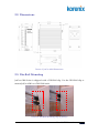
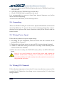
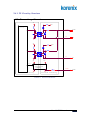
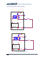
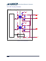
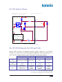
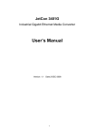
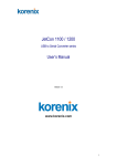
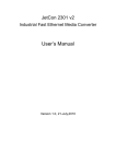
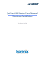
JetCon 6300 Series User Manual
Hardware Installation
First Edition, July 2008
www.korenix.com
Copyright Notice
Copyright© 2008 Korenix Technology Co., Ltd.
All rights reserved.
Reproduction without permission is prohibited.
Information provided in this manual is intended to be accurate and reliable.
However, the original manufacturer assumes no responsibility for its use, or
for any infringements upon the rights of third parties that may result from its
use.
The material in this document is for product information only and is subject
to change without notice. While reasonable efforts have been made in the
preparation of this document to assure its accuracy, Korenix assumes no
liabilities resulting from errors or omissions in this document, or from the use
of the information contained herein.
Korenix reserves the right to make changes in the product design without
notice to its users.
Acknowledgments
Korenix is a registered trademark of Korenix Technology Co., Ltd.
All other trademarks or registered marks in the manual belong to their
respective manufacturers.
[email protected]
1
Industrial Smart Ethernet I/O Converter
Table of Contents
1.
OVERVIEW ..................................................................................................................................3
1.1.
PACKAGE CHECKLIST .............................................................................................................3
1.2.
ABOUT THIS MANUAL ............................................................................................................3
2.
HARDWARE INSTALLATION..................................................................................................4
2.1.
APPEARANCE .........................................................................................................................4
2.2.
DIMENSIONS ...........................................................................................................................5
2.3.
DIN-RAIL MOUNTING .............................................................................................................5
2.4.
GROUNDING ...........................................................................................................................6
2.5.
WIRING POWER INPUT ...........................................................................................................6
2.6.
WIRING I/O CHANNELS ..........................................................................................................6
2.6.1.
DI Circuitry Structure .......................................................................................................7
2.6.2.
DI Interface Dry Contact Wiring ......................................................................................8
2.6.3.
DI Interface Wet Contact Wiring.......................................................................................9
2.6.4.
DO Circuitry Structure ...................................................................................................10
2.6.5.
DO Interface Wiring ....................................................................................................... 11
2.6.6.
DI / DO Wiring and On / Off Logic Table....................................................................... 11
2.7.
3.
WIRING FAST ETHERNET PORT .............................................................................................12
TECHNOLOGY DATA ..............................................................................................................13
3.1.
JETCON 6330 .......................................................................................................................13
3.2.
JETCON 6350 .......................................................................................................................15
4.
FURTHER SUPPORT................................................................................................................17
2
www.koreix.com
1. Overview
The Korenix JetCon 6300 series is a smart Ethernet I/O converter with
multiple digital input and output channels. JetCon 6300 converts the signal of
each I/O channel into Ethernet messages. The input channels support either
digital-input mode or event-counter mode, while the output channels provide
digital-output mode or pulse-output mode. User can monitor the real-time
status or control all the channels remotely through the built-in Ethernet
connectivity.
In addition to remote data acquisition and channel control, JetCon 6300 is
programmable with smart I/O rules. An event of logic rule can be defined to
modify the status of digital output channel either on the same device or to
multiple JetCon 6300 series devices. With the user defined logic rules,
multiple JetCon 6300 devices can execute the programmed control logic
without further step in by user or other controls.
JetCon 6300 is constructed by aluminum case with IP31 protection for
industrial environment and the Din-Rail mounting is easy to install in control
box with limited spaces. The configuration is user friendly and the
management interfaces include JetCon 6300 Commander, Web, as well as
Modbus/TCP protocol.
1.1. Package Checklist
JetCon 6300 is shipped with the following items. If any of these items is
missing or damaged, please contact your customer service representative for
assistance.
y
JetCon 6300 unit with attached mounting clip
y
Terminal blocks for power connecter and I/O channels
y
Documentation and Software CD-ROM
y
Quick Installation Guide
1.2. About This Manual
This manual provides detailed information for both hardware installation and
software configuration. The software configuration is composed of JetCon
6300 Series Utility, Web configuration and Modbus/TCP configuration.
[email protected]
3
Industrial Smart Ethernet I/O Converter
2. Hardware Installation
2.1. Appearance
Picture 1 JetCon 6330 Appearance
Picture 2 JetCon 6350 Appreance
4
www.koreix.com
2.2. Dimensions
Picture 3 JetCon 6300 Dimensions
2.3. Din-Rail Mounting
JetCon 6300 Series is shipped with a DIN-Rail clip. Use the DIN-Rail clip to
mount JetCon 6300 on a DIN-Rail track.
Picture 4 Din-Rail Mounting step (a) and (b)
[email protected]
5
Industrial Smart Ethernet I/O Converter
a. Insert the upper end of DIN-Rail clip into the back of DIN-Rail track from
its upper side.
b. Push the bottom of DIN-Rail clip into the track.
c. Check if DIN-Rail clip is attached on the track.
It is recommended to reserve at least 5mm interval between two JetCon
devices for heat dispersing.
To remove from the track, reverse the steps above.
2.4. Grounding
There is an Earth Ground pin on the Power Input terminal block at the bottom
of JetCon 6300 Series. To prevent the system from being damaged by noise or
electrical shock, please make exact connection with JetCon devices with the
Earth Ground.
2.5. Wiring Power Input
Follow the steps below for power input wiring:
1. According the pin assignment, insert the wires into the contacts on the
terminal block connector.
2. Tighten the wire-clamp screws to prevent DC wires from being loosened.
3. Connect to and turn on the power source. The range of the suitable power
source is from 12 to 24 AWG.
4. When the unit is ready, the PWR LED turns yellow, the RDY LED turns
green.
Note: It is a good practice to turn off the power and unplug the
terminal block before making wire connections. Otherwise, your
screwdriver blade can inadvertently short the terminal connections to
the grounded enclosure.
2.6. Wiring I/O Channels
Follow the pin assignment to insert the I/O wires into the front contacts of the
terminal block. Tighten the wire-clamp screws to prevent the I/O wires from
being loosened.
6
www.koreix.com
2.6.1. DI Circuitry Structure
DI Circuitry Structure
+5V
Viso
Controller
DI.COM
4
1
3
2
DI.0
DI.PWR
DI.0
+5V
Viso
4
1
3
2
DI.1
Viso
+5V
nPWR_EN
DI.1
Power 5V
Isolation
(3KVdc)
DI.GND
DI.GND
iso
Internal Circuitry
Isolated Circuitry
Picture 5 DI Circuit Structure
[email protected]
7
Industrial Smart Ethernet I/O Converter
2.6.2. DI Interface Dry Contact Wiring
Digital Input
OFF State (Readback as 0)
Dry Contact
SW = Open
Viso
DI.COM
4
1
3
2
SW
DI.x
1
2
Viso
+5V
Power 5V
Isolation
(3KVdc)
DI.GND
iso
Digital Input
ON State (Readback as 1)
Dry Contact
SW = Close to GND
Viso
DI.COM
4
1
3
2
SW
DI.x
1
+5V
Viso
Power 5V
Isolation
(3KVdc)
DI.GND
iso
Picture 6 DI Dry Contact Wiring
8
www.koreix.com
2
2.6.3. DI Interface Wet Contact Wiring
Digital Input
Wet Contact
OFF State (Readback as 0)
SW = Open or Vt < 3 Vdc
Viso
4
1
3
2
1
DI.COM
Vt
SW
1
2
2
DI.x
Viso
+5V
Power 5V
Isolation
(3KVdc)
DI.GND
iso
Digital Input
ON State (Readback as 1)
Wet Contact
SW = Close and Vt = 3.5 ~ 30Vdc
Viso
4
1
3
2
1
DI.COM
Vt
1
+5V
2
2
SW
DI.x
Viso
Power 5V
Isolation
(3KVdc)
DI.GND
iso
Picture 7 DI Wet Contact Wiring
[email protected]
9
Industrial Smart Ethernet I/O Converter
2.6.4. DO Circuitry Structure
DO Circuitry Structure
+5V
Viso
DO.PWR
Controller
1
4
2
3
DO.0
3
DO.0
DO.PWR
2
1
+5V
Viso
1
4
2
3
DO.1
3
DO.1
2
1
Viso
+5V
nPWR_EN
Power 5V
Isolation
(3KVdc)
DO.GND
iso
Internal Circuitry
Isolated Circuitry
Picture 8 DO Circuit Structure
10
www.koreix.com
DO.GND
2.6.5. DO Interface Wiring
Digital Output
(Sink Type)
ON State (Readback as 1)
OFF State (Readback as 0)
Short to GND
Vt
Viso
1
DO.PWR
1
Vt
4
Load
2
DO.y
3
3
2
200mA
2
1
+5V
Viso
Power 5V
Isolation
(3KVdc)
DO.GND
2000mA
iso
Picture 9 DO Channel Wiring
2.6.6. DI / DO Wiring and On / Off Logic Table
JetCon 6300 provides an internal isolated voltage, called Viso, for DI/DO
contacts. Viso can be turn on/off through management. The relationship of Viso
state, DI/DO wiring and the result of channel is summarized below:
Viso = ON
ON State
OFF State
Viso = OFF
ON State
OFF State
DI
Dry Contact
SW=Close to GND
SW=Open
N/A
N/A
DI
Wet Contact
Vt= 3.5 ~ 30Vdc
and
SW=Close
DO
Load with Vt,
200mA max
SW=Open
or
Vt< 3Vdc
Load
without
current
Vt=3.5 ~ 30Vdc
and
SW=Close
Load with Vt
(Vt>=4Vdc),
200mA
SW=Open
or
Vt< 3Vdc
Load
without
current
Viso: an isolated power supply
Vt: The power voltage from an external device
[email protected]
11
Industrial Smart Ethernet I/O Converter
Table 1
DI/DO Wiring and On/Off Logic Table
2.7. Wiring Fast Ethernet Port
The fast Ethernet port of JetCon 6300 series supports either 10Base-T or
100Base-TX, full or half duplex modes. The port detects the signal from the
peer device to negotiate the link speed and duplex mode automatically. The
port is also capable of Auto MDI/MDIX which allows connect another switch,
hub or workstation by either a straight through or a crossover cable.
Plug one end of an Ethernet cable into the fast Ethernet port and connect the
other end to the attached switch or host. The link LED lights up if the cable is
correctly connected. Always make sure that the cable length is less than 100
meters (328 feet).
LED Indication of LAN:
Link Active: Green On & Blinking
Link Speed:
Yellow off for 10Base-T
Yellow on for 100Base-TX
The wiring cable types are as below.
10Base-T: 2-pair UTP/STP Cat. 3, 4, 5 cable, EIA/TIA-568 100-ohm (100m)
100 Base-TX: 2-pair UTP/STP Cat. 5 cable, EIA/TIA-568 100-ohm (100m)
1000 Base-TX: 4-pair UTP/STP Cat. 5 cable, EIA/TIA-568 100-ohm (100m)
12
www.koreix.com
3. Technology Data
3.1. JetCon 6330
System
Isolated Power supply
CPU: 100MHZ, RISC-Based
Power supply: 5V/200mA, power on/off with
SDRAM: 32K bytes
Configuration
Flash ROM: 512K bytes
Isolation Voltage: 3KVdc
EEPROM: 2K bytes
Watchdog: embedded watchdog to auto reset system
Features
when system failure
Network Protocols: IP, TCP, UDP, HTTP, BOOTP,
LED:
DHCP, Modbus/TCP
PWR: Power Input plugged and On (Green)
Configuration: Windows Utility, Web browser,
RDY: System startup ready (Yellow)
Firmware update
STS: System fail (Red)
Windows Utility: JetCon 6300 Commander
Logic Rules: Conditions of the DI/Counter values,
Network Interface
Actions include DO/Pulse, Counter, Peer to Peer
Ethernet: IEEE 802.3 10Base-T, IEEE 802.3u
Peer to Peer: One to one, multiple to one or one to
100Base-TX
multiple peers
Connector: 1 * RJ-45, Auto MDI/MDI-X
Protection: Built-in 1.5 KV magnetic isolation
Power Requirements
protection
System Power: external unregulated +24V (10-30V)
LED:
Power Consumption: Max. 2W
LAN Activity: Green On & Blinking
Network Speed: 10M (Yellow Off) /100M (Yellow ON)
Mechanical
Dimensions: 120 (H) x 55 (W) x 99 (D) mm
Digital Input
Mounting: Din-Rail
Input Channels: 16 Channels
Material: Aluminum
Input Type: source type
Input Mode: DI or event counting
Environmental
DC Input: 30V max
Regulatory Approvals: EMI: FCC Class B;
Threshold Voltage: 3.8V
CE/EN55022:2003, Class B;
Responding Time to Host PC Request: <2ms
CE/EN61000-3-2:2000 Harmonic test;
Isolation Voltage: 3.75KVrms
CE/EN61000-3-3:1995 Flicker test
EMS:
EN61000-4-2:2001, ESD test, Level 3(Contact +/- 6KV,
[email protected]
13
Industrial Smart Ethernet I/O Converter
Air +/- 8KV)
Free Fall: IEC60068-2-32
EN61000-4-3:2002, RS test, Level 3 (10V/m)
Operating Temperature: -25 ~ 70°C
EN61000-4-4:2004, EFT test, Level 3 (Power supply +/-
Operating Humidity: 20 ~ 90% non-condensing
2KV/5KHz, I/O 1KV/5KHz)
Storage Temperature: -40 ~ 85°C
EN61000-4-5:2001, Surge test, Level 3 (L-N: +/- 2KV)
Warranty: 3 years
EN61000-4-6:2003, CS test, Level 3
Vibration: IEC60068-2-6
Ordering Information
Shock: IEC60068-2-27
JetCon 6330 16-CH DI Smart Ethernet I/O Converter
14
www.koreix.com
3.2. JetCon 6350
System
Working Range: 5-30VDC
CPU: 16 bits/100MHZ, RISC-Based
Driving Capacity: 200mA @23°C
SDRAM: 32K bytes
Responding Time to Host PC Request: <2ms
Flash ROM: 512K bytes
Output Initial State: Programmable
EEPROM: 2K bytes
Isolation Voltage: 3.75KVrms
Watchdog: embedded watchdog to auto reset system
Protection: over-current 400mA/channel trip @23°C
when system failure
LED:
Isolated Power supply
PWR: Power Input plugged and On (Green)
Power supply: 5V/200mA, power on/off with
RDY: System startup ready (Yellow)
Configuration
STS: System failure (Red)
Isolation Voltage: 3KVdc
Network Interface
Features
Ethernet: IEEE 802.3 10Base-T, IEEE 802.3u
Network Protocols: IP, TCP, UDP, HTTP, BOOTP,
100Base-TX
DHCP, Modbus/TCP
Connector: 1 * RJ45, Auto MDI/MDI-X
Configuration: Network, I/O setting, Watchdog,
Protection: Built-in 1.5 KV magnetic isolation
Firmware update
protection
Windows Utility: JetCon 6300 Commander
LED:
Logic Rules: Conditions of the DI/Counter values,
LAN Activity: Green On & Blinking
Actions include DO/Pulse and Counter, Peer to peer
Network Speed: 10M (Green Off) / 100M(Green ON)
Power Requirements
Digital Input
System Power: external unregulated +24V (10-30V)
Input Channels: 12 Channels
Power Consumption: Max. 2W
Input Type: source type
Input Mode: D/I or event counting
Mechanical
DC Input: 30V max
Dimensions: 120 (H) x 55 (W) x 99 (D) mm
Threshold Voltage: 3.8V
Mounting: Din-Rail
Responding Time to Host PC Request: <2ms
Material: Aluminum
Isolation Voltage: 3.75KVrms
Environmental
Digital Output
Regulatory Approvals:
Output Channels: 4 Channels
EMI:
Output Type: FET output, sink type
FCC Class B;
Output Mode: Level or pulse output with
CE/EN55022:2003, Class B;
programmable pulse width
CE/EN61000-3-2:2000 Harmonic test;
[email protected]
15
Industrial Smart Ethernet I/O Converter
CE/EN61000-3-3:1995 Flicker test
with criterion performance A
EMS:
EN61000-4-6:2003, CS test, Level 3 with criterion
EN61000-4-2:2001, ESD test, Level 3 (Contact +/- 6KV,
performance A
Air +/- 8KV) with criterion performance A
Vibration: IEC60068-2-6
EN61000-4-3:2002, RS test, Level 3 (10V/m) with
Shock: IEC60068-2-27
criterion performance A
Free Fall: IEC60068-2-32
EN61000-4-4:2004, EFT test, Level 3 (Power supply +/-
Operating Temperature: -25 ~ 70°C
2KV/5KHz, I/O 1KV/5KHz) with criterion performance A
Operating Humidity: 20 ~ 90% non-condensing
EN61000-4-5:2001, Surge test, Level 3 (L-N: +/- 2KV)
Storage Temperature: -40 ~ 85°C
16
www.koreix.com
4. Further Support
Korenix Technologies Co., Ltd.
9F, No. 100-1, Ming-Chuan Rd., Shing Tien City, Taipei, Taiwan
Tel: +886-2-82193000
Fax: +886-2-82193300
Business service: [email protected]
Customer service: [email protected]
[email protected]
17