1
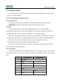
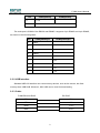
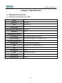
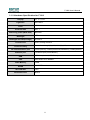
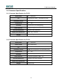
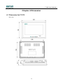
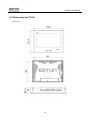
F1000 User's Manual (Version: V1.01) Version History NO. Date Version Description 1 2011-04-13 V1.00 Initial release. 2 2013-09-02 V1.01 Optimizes document. F1000 User's Manual Contents Chapter 1 Overview ..................................................................................................2 Chapter 2 Installation ...............................................................................................3 2.1 Installation guide ............................................................................................3 2.1.1 Installation position ............................................................................................. 3 2.1.2 NEMA4 standard installation............................................................................... 3 2.1.3 Environment precautions .................................................................................... 3 2.2 Power connection ..........................................................................................4 2.2.1 Power requirements ........................................................................................... 4 2.2.2 Grounding requirement....................................................................................... 5 2.2.3 CE Requirement................................................................................................. 5 2.2.4 Safety Guide ...................................................................................................... 5 2.3 Communication connection ............................................................................7 2.3.1 Connection with external device ......................................................................... 7 2.3.2 USB interface ..................................................................................................... 8 2.3.3 Cable ................................................................................................................. 8 2.4 Requirement ..................................................................................................9 Chapter 3 Specification .........................................................................................10 3.1 Hardware Specification ................................................................................10 3.1.1 Hardware Specification for F1070 ..................................................................... 10 3.1.2 Hardware Specification for F1100 ...................................................................... 11 3.2 Common Specification .................................................................................12 3.2.1 Common Specification for F1070 ...................................................................... 12 3.2.2 Common Specification for F1100 ...................................................................... 12 Chapter 4 Dimension .............................................................................................13 4.1 Dimension for F1070 ....................................................................................13 4.2 Dimension for F1100 ....................................................................................14 1 F1000 User's Manual Chapter 1 Overview Environment F1000 series is designed according to the application environment of industrial products. It can stably work in the most industrial environment. However, it may not be used in some specific environment, if you need to use special occasions in the outdoor, please be sure to ask your provider! NEMA The front panels of F1000 series products meet the NEMA4 protection regulations. When the product is properly installed in accordance with the panel on NEMA4 protection regulations, the cabinet still remain in compliance with the provisions of NEMA4, that to say, when the panel surface spray liquid, the liquid can’t penetrate into the inner of disk cabinet. Electrical environment The products have passed the test to demonstrate compliance with European CE Electrical Certification Standard, that to say, the interference circuit design of products can resist electrical noise, but this is no guarantee that it may be exempted from all cases. The correct wiring and grounding mode can ensure the use. Mechanical environment To ensure that your correct use, please avoid installing the product in the presence of strong mechanical vibration environment. 2 F1000 User's Manual Chapter 2 Installation 2.1 Installation guide 2.1.1 Installation position Please keep distance between the product and the interface of electric equipment, such as AC power cord, the PLC output module, contactor, starter, relay, and so on. Please especially caution that keep distance with the variable frequency speed governor and switching power supply. Because this kind of devices’ input and output cable must be shielded cable, and the shielding net access to system’s star ground. 2.1.2 NEMA4 standard installation Cabinet details F1000 series product can be installed at a depth of more than 105 mm, we recommend you install the product at the front panel of the cabinet. To ensure that normally open the front panel of the cabinet, please keep at least 25 mm distance around the installation products. NEMA-4 installation Puts the product into the mounting holes, and then respectively screw the 4 screws into the screw fixing hole from the back of panel, then tighten the screws one by one, till the product is firmly fixed on the panel. [Caution] Do not be too hard to screw the screws! Installation standard To ensure compliance with the seal specification of NEMA4, all mounting screws is provides with the product must be used, and the installation panel bending cannot be over 0.010°. 2.1.3 Environment precautions Because the built-in LCD display panel, F1000 series product are restricted to indoor use. Please ensure that the product is installed correctly, and the environment is in accordance with the constraints of hardware specification (for details, please refer to the hardware specification). Do not use in hazardous situations, such the flammable gas, the steam, the dust. Do not use in great changes of temperature or humidity, it may lead to internal device condensed water, resulting in damage to the device. 3 F1000 User's Manual 2.2 Power Before installing the product, please ensure the power supply is consistent with the electrical standard of the local and the country, for the details please consult the local suppliers. 2.2.1 Power requirements Power To be compatible with most DC power supply, F1000 series product can only use DC power supply, the regulations range of DC voltage is19.2 V ~28.8 V. The product internal power conditioning circuit is completed by the switch power supply, the peak of starting current can achieve 700mA. High voltage the internal of products have the power supply isolation protection function, it works when the power voltage is too high, but this doesn’t ensure that the internal electronic components are not damaged. DC power supply must be correctly isolated from AC main power supply. Emergency stop switch to meet the ICS security recommendations, you must install the emergency stop switch in any control system of F1000 series product. Power status never use the same power with perceptual load or the input circuit of the controller. [Note] Some controller provide 24V output DC power, cannot provide normal current for F1000 series product. Wiring DC power supply lines should be as short as possible: Shielded cable is not more than 500 meters; the common twisted pair is not more than 300 meters. The power cables suggest using the twisted pair cable. If the power cable will be exposed to lighting environment, please use the lighting protection measures appropriate or proper installation lightning protection device. Please be sure to AC power cable and high energy with fast switching away from the communication signal cable. To provide relief channel to static electricity and high frequency interference, please parallel connect a resistance or a capacitance between no grounding DC power and the earth. Generally, the resistance value is 1MΩ, the capacitor capacity is 4700pF. 4 F1000 User's Manual Connection The end of the cable crimping terminal is used to 3/8〞insulation when connect the power cable (recommend to use the forked terminal). Counterclockwise screw the screwing in the product back, insert the power cable with the crimped terminal, and then clockwise screw the screws. The power positive must connect to the terminal marked with 24V, the DC grounding connect to the terminal marked with 0V. 2.2.2 Grounding requirement Product shell must be grounded. The DC grounding is not connected to the earth in the product internal. To avoid the virtual point grounding caused by external noise into the system, it is best not to the DC grounding and shell connect to the earth, but if must grounding to the star ground, it is ensure that the conductor grounding as a short length, cross-sectional area as large as possible. The conductor must be able to withstand the maximum short-circuit current, and it must be directly connected to star ground, so that, the grounding conductor will not bear the other branch current. 2.2.3 CE Requirement To comply with the EMC specification, and reduce the electrical noise interference, the grounding terminal at the product shell must be ground cable with a separate #14 AWG specifications, it should directly connected to the system ground star follow the installation introduction. 2.2.4 Safety Guide This section introduces the recommended installation practices and procedures. Although no two-application cases are same, please carefully read the following suggestions before installation. 5 F1000 User's Manual Hardware System designers must understand that there may be some unsafe factors from the failure of the control system device, and the electrical conflict in the operation interface could cause the device to start, this may lead to a certain degree of damage to the operator. If you or your company needs the operation interface when use a programmable control system, you must understand the potential security risks and take some appropriate preventive measures. Although your detailed design steps are constituted according to your specific application, you need to pay attention to the general prevention matters about installing programmed control firmware. These precautions meet NEMA ICS 3-304 control standard. Program Attention To meet the security proposed of ICS, you must check whether the program exist safety constraints about the can-write register of hazardous parts. Moreover, to ensure personal safety, the device must be equipped with an emergency stop. ICS 3-304.81 safety recommendations: Carefully consider the function of the emergency stop; it must be independent of the programmable controller outside. In the operator can directly contact mechanical position, such as loading and unloading machine tool position or the machine automatic-run position, you must carefully consider the function of the manual device or the other alternate method. It needs to be independent of the programmable controller outside, can automatic start or stop the system. If you need to modify the program in the system-running situation, you should take measures to ensure the modification is the necessary. *These suggestions are to prevent the risk of device failure. ● ICS3-304.81 safety recommendations is in the permission of the NEMA, and copy from NEMA ICS 3-304 standard. 6 F1000 User's Manual 2.3 Communication You can see the communication port on the back of the shell, can be used to connect such as PLC or external devices. 2.3.1 Connected with external device Cable requirements With different external devices should be connected different communication cables. [WARNING] Never plug communication cable when the device power on. Attention To avoid the problem of communication, please pay attention to that: the length of communication cable with the connection of RS485 is no more than 150meters; the length of communication cable with the connection of RS232 is no more than 15meters. When the communication cable is too long or the communication cable needs to through the electrical noise environment, you must make the communication cable by the shielding cable. Do not wire the communication cable and AC power cable together or wire the communication cable near the position of electrical noise source. Please ensure that both ends of the connector communication cable and communication port is connected closely and fixation. Pin configuration There are two DB9 ports on the F1000 series product, one is D-type male port, and the other is D-type female port. The male port is COM1 and COM3 of the RS232, as shown in the following table. Pin COM1[RS232] 1 Not used 2 RxD 3 TxD 4 5 TxD GND 6 7 COM3[RS232] RxD RTS 7 F1000 User's Manual Pin COM1[RS232] 8 CTS 9 Not used COM3[RS232] The male port is COM2 of the RS232 and RS485; it supports 2-pin RS485 and 4-pin RS485, as shown in the following table: Pin 1 COM2[RS485]2w COM2[RS485]4w Data- 2 3 4 Data+ 5 6 Rx- 7 Rx+ 8 Tx- 9 Tx+ 2.3.2 USB interface Standard USB 2.0 interface can connect many devices, such as the mouse, the flash memory disk, USB HUB. Moreover, Mini USB can be used for downloading. 2.3.3 Cable F1000 Ethernet RJ45 PC RJ45 1TX+ 3RX+ 2TX- 6RX- 3RX+ 1TX+ 6RX- 2TX+ 8 F1000 User's Manual 2.4 Requirement CE criterion The provisions of EMC about counteracting the electromagnetic radiation: 89/336/EEC, 92/31/EEC, 93/68/EEC. The provisions of the mechanical structure about machinery safety: 89/392/EEC, 91/368/EEC, 93/44/EEC, 93/ 68/EEC. F1000 series product use CE markers to conform to EMC. The design of the F1000 series product can work well in the electromagnetic noise environment without electromagnetic radiation noise. The products meet the European standard for electrical safety by the correct installation. Compatibility The design of the F1000 series product meet the electromagnetic compatibility in the industry environment, the items are as follows: CISPR (EN 55011) Group 1, Class A Radiation levels EN50081-2 industrial environment common radiation standard (be equivalent to USA FCC Class A Standard) EN50082-2 industrial environment common resistance standard 9 F1000 User's Manual Chapter 3 Specification 3.1 Hardware Specification 3.1.1 Hardware Specification for F1070 Display Lightness Color Contrast ratio Resolving power (WxH dots) Backlight Backlight life (Average) Touch panel Touch accuracy I/O Communication port Ethernet port 7〞 TFT LCD 300 cd/m2 65536 colors 500:1 800x480 LED 30,000 hr 4 pin analog resistive touch screen Active Area Length(X)±2%,Width(Y)±2%, COM1(RS232), COM2(RS485/2W,RS485/4W), COM3(RS232) 1 Ethernet port(10/100 Base/T) USB USB Host port x 1,USB Client port x 1 CPU 32bit RISC CPU 400MHz Flash Memory DRAM SD Card Slot Real-time clock 128M 64M DDR2 on board YES Built-in 10 F1000 User's Manual 3.1.2 Hardware Specification for F1100 Display Lightness Color Contrast ratio Resolving power (WxH dots) Backlight Backlight life time(Average) Touchscreen Touch accuracy I/O Communication port Ethernet port 10” TFT LCD 300 cd/m2 65536 colors 500: 1 800x480 LED 30,000 hr 4 wire, analog resistive Active Area Length(X)±2%,Width(Y)±2%, COM1(RS232), COM2(RS485/2W,RS485/4W), COM3(RS232) 1 Ethernet port(10/100 Base/T) USB USB Host port x 1,USB Client port x 1 CPU 32bit RISC CPU 400MHz Flash Memory DRAM SD Card Slot Real-time clock 128M 64M DDR2 on board YES Built-in 11 F1000 User's Manual 3.2 Common Specification 3.2.1 Common Specification for F1070 Input power CE Protection levels Temperature 24 ±20%VDC EN61000-6-2:2005, EN61000-6-4:2007 IP65, the front panel is circular sealing ring 0℃~45℃ Humidity 10-90% RH (no condensation) Shell material Engineering plastics ABS + PC Overall dimensions Open hole dimensions Weight WxHxD 202x148x43mm WxH 192 x 138 mm About 0.7kg 3.2.2 Common Specification for F1100 Input power 24 ±20%VDC Power waste 300 mA@24VDC CE Protection levels Temperature EN61000-6-2:2005, EN61000-6-4:2007 IP65, the front panel is circular sealing ring 0℃~45℃ Humidity 10-90% RH (no condensation) Shell material Engineering plastics ABS + PC Overall dimensions Open hole dimensions Weight WxHxD 270.5x212.5x52mm WxH 259 x 201 mm About1.3 kg 12 F1000 User's Manual Chapter 4 Dimension 4.1 Dimension for F1070 Unit: mm 13 F1000 User's Manual 4.2 Dimension for F1100 Unit: mm 14