1
GSM GPRS Modem
900 / 1800
Value Added Feature
USER MANUAL
Confidential, the whole present document is the sole property of Fargo Telecom (Asia) Ltd.
Revision history
Rev.
0.9
0.91
Date
22July 2005
22Feb 2006
0.92
21Apr 2006
0.94
3OCT2006
Details
First release
- Remove AT command history feature
- Remote AT command : when enabled all incoming SMS
will be erased
AutoTCP/UDP : Add DCD/DSR signaling
: modify command/data mode switching
Support Fargo Maestro 100 Lite
New Feature : AT command driven TCP/UDP connection
Call screening
VAF AT commands can be sent over SMS
Originated by
Wallace Lee
Wallace Lee
Wallace Lee
Wallace Lee
Fargo Maestro is a registered trademark of Fargo Telecom Asia Ltd.
This manual is written without any warranty. Fargo Telecom Asia Ltd reserves the right to modify or improve the
product and its accessories which can also be withdrawn without prior notice.
Besides, our company stresses the fact that the performance of the product as well as accessories depends not
only on the proper conditions of use, but also on the environment around the places of use.
Fargo Telecom Asia Ltd assumes no liability for damage incurred directly or indirectly from errors, omissions or
discrepancies between the modem and the manual.
Confidential, the whole present document is the sole property of Fargo Telecom (Asia) Ltd.
Table of contents
1.
INTRODUCTION.................................................................................................................................................................................................... 3
2.
INSTALLATION ..................................................................................................................................................................................................... 3
2.1.
2.1.1.
2.2.
3.
2.2.2.
Downloading the file .................................................................................................................................................... 4
GPRS AND TCP/UDP PARAMETERS SETUP..................................................................................................................................................... 6
3.2.
AT+IPGPRS command ................................................................................................................................................. 6
ACTIVATING GPRS CONNECTION ....................................................................................................................................... 7
AT+CGATT command.................................................................................................................................................. 7
3.2.2.
AT+IPCONNECT command ........................................................................................................................................ 7
TCP/UDP PARAMETERS SETUP .......................................................................................................................................... 8
3.3.1.
AT+IPTCP command.................................................................................................................................................... 8
3.3.2.
AT+IPUDP command ................................................................................................................................................. 10
3.3.3.
AT+IPBUFF command ............................................................................................................................................... 11
AUTOMATIC AND SELF-RECOVERY TCP/UDP CONNECTION ...................................................................................................................... 13
4.1.
FLOW DIAGRAM OF AUTO TCP/UDP CONNECTION FUNCTION .......................................................................................... 14
4.2.
AT COMMANDS FOR AUTO TCP/UDP CONNECTION ......................................................................................................... 15
4.2.1.
AT+AUTOTCP command .......................................................................................................................................... 15
4.2.2.
AT+AUTOUDP command.......................................................................................................................................... 16
AT COMMAND DRIVEN TCP/UDP CONNECTION ............................................................................................................................................ 18
5.1.
AT COMMANDS FOR AUTO TCP/UDP CONNECTION ......................................................................................................... 18
5.1.1.
AT+DLEMODE command ......................................................................................................................................... 18
5.1.2.
AT+OTCP command .................................................................................................................................................. 19
5.1.3.
AT+OUDP command.................................................................................................................................................. 19
REMOTE AT COMMAND BY SMS...................................................................................................................................................................... 21
6.1.
DESCRIPTION OF THE OPERTATION.................................................................................................................................... 21
6.2.
AT COMMAND FOR CONFIGURING AT COMMAND .............................................................................................................. 22
6.2.1.
6.3.
7.
GPRS NETWORK PARAMETERS .......................................................................................................................................... 6
3.2.1.
3.3.
6.
INSTALLING THE VALUE ADDED FEATURE ........................................................................................................................... 3
Erasing the IP connectivity feature (AT# feature) (Fargo Maestro 100 only) ............................................................... 3
3.1.1.
5.
Identifying Fargo Maestro ............................................................................................................................................ 3
2.2.1.
3.1.
4.
IDENTIFYING YOUR FARGO MAESTRO ................................................................................................................................ 3
AT+SMSAT command................................................................................................................................................ 22
LIMITATION AND CAUTION TO BE TAKEN WHEN USING REMOTE AT COMMAND ................................................................. 22
I/O TRIGGERED AT COMMAND......................................................................................................................................................................... 24
Confidential, the whole present document is the sole property of Fargo Telecom (Asia) Ltd.
1
7.1.
DESCRIPTION OF THE OPERTATION.................................................................................................................................... 24
7.2.
AT COMMAND FOR CONFIGURING I/O TRIGGERED AT COMMAND ..................................................................................... 25
7.2.1.
7.3.
8.
10.
11.
NOTES AND CAUTIONS TO BE TAKEN WHEN USING I/O TRIGGERED AT COMMAND ............................................................ 26
CALL SCREENING ............................................................................................................................................................................................. 27
8.1.
9.
AT+IOAT command.................................................................................................................................................... 25
AT COMMAND FOR CONFIGURING CALL SCREENING ......................................................................................................... 27
8.1.1.
AT+CSRN command .................................................................................................................................................. 27
8.1.2.
AT+CSNW command ................................................................................................................................................. 27
8.1.3.
AT+CSNR command .................................................................................................................................................. 28
8.1.4.
AT+CSND command.................................................................................................................................................. 29
KNOWN ISSUES ................................................................................................................................................................................................. 30
9.1.
AT+WIND COMMAND ..................................................................................................................................................... 30
9.2.
SAVING OF PARAMETERS TO NON-VOLATILE MEMORY ...................................................................................................... 30
9.3.
MUTUALLY EXCLUSIVE TCP/UDP FUNCTIONS. ................................................................................................................ 30
9.4.
SENDING VAF AT COMMANDS OVER SMS ....................................................................................................................... 30
QUESTIONS AND ANSWERS ............................................................................................................................................................................ 31
10.1.
INSTALLATION .................................................................................................................................................................. 31
10.2.
AUTOTCP/UDP ............................................................................................................................................................... 31
10.3.
AT COMMAND DRIVEN TCP/UDP CONNECTION ............................................................................................................... 31
10.4.
RMOTE AT COMMAND BY SMS ........................................................................................................................................ 32
10.5.
I/O TRIGGERED AT COMMAND .......................................................................................................................................... 32
EXAMPLES OF VAF SETUP AND OPERATION................................................................................................................................................ 33
11.1.
TO MAKE A AT COMMAND DRIVEN TCP CONNECTION ...................................................................................................... 33
11.2.
TO SETUP A AUTOMATIC TCP CONNECTION ...................................................................................................................... 33
Confidential, the whole present document is the sole property of Fargo Telecom (Asia) Ltd.
2
1. INTRODUCTION
Fargo Maestro Value-Added Feature (VAF) package is a software solution for Fargo Maestro modem (*note 1). New
functions added to increase application range of various industrial and automated applications:
-
Automatic and self-recovery TCP/UDP socket connection (*note 2)
-
AT command driven TCP/UDP socket connection (*note 2)
-
Remote AT command (AT command through SMS)
-
I/O triggered AT command execution
-
Call screening (reject call made by unauthorized phone number)
Users can configure and use the above features by AT commands.
Note 1: Not all Fargo Maestro can have this feature installed. Please refer to Chapter 2
Note 2: For Fargo Maestro 100 with TCP/IP and Fargo Maestro 100 Lite only
2. INSTALLATION
2.1. Identifying your Fargo Maestro
Not all Fargo Maestro can have the Value-added feature installed, so you need to check your Fargo Maestro modem
before installation.
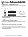
2.1.1. Identifying Fargo Maestro by AT command
Start HyperTerminal, choose correct baud rate to communicate with the modem
(Fargo Maestro 20/100Lite: 9600bps, 8N1; Fargo Maestro 100: 115200bps, 8N1 )
Then enter the following and see the response according to the following table:
Model
Fargo Maestro 20
Fargo Maestro 100
Fargo Maestro 100 Lite
Command
AT+WOPEN=2
AT+WOPEN=2
AT+WOPEN=2
Expected response
+WOPEN: 2,"AT v02.10"
+WOPEN: 2,"AT v02.10","AT v02.10"
+WOPEN: 2,"AT v03.01"
If you get the same response then this modem is ready for installation.
2.2. Installing the Value added feature
2.2.1. Erasing the IP connectivity feature (AT# feature) (Fargo Maestro 100 only)
For Fargo Maestro 100, you need to erase the IP connectivity feature before downloading the Value added feature. Again,
on HyperTerminal enter the following commands step by steps:
Command entered
AT+WOPEN=0
AT+WOPEN=3
AT+WOPEN=4
Expected response
(modem will reset)
OK
(modem will reset)
Confidential, the whole present document is the sole property of Fargo Telecom (Asia) Ltd.
3
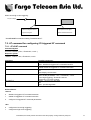
2.2.2. Downloading the file
a. Check the HyperTerminal is configured with setting “8 data bits, no parity, 1 stop bit, and hardware flow control
(CTS/RTS)
b. For Fargo Maestro 20 and Fargo Maestro 100 Lite, it is suggested to set the baud he RS232 link is changed to 115200
bps. You can first start HyperTerminal session with 9600 bps. The on the screen type command AT+IPR = 115200 and
then press “Enter”. Then change the HyperTerminal speed to 115200bps. (For Fargo Maestro 100 the default speed is
115200bps)
c. On the screen type the command AT+WDWL and then press “Enter”. The modem should answer +WDWL: 0, and then
a series of strange characters appear or the cursor is just moving forward slowly. (the modem is sending the first
characters of the Xmodem protocol).
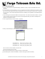
d. Then on HyperTerminal you choose “Transfer” –“Send File”
e. When you see the dialog box, on the “Filename” you choose file according to the modem:
Fargo Maestro 20 : FM20_VAF_094_OAT210_16.dwl
Fargo Maestro 100 : FM100_VAF_094_OAT210_32.dwl
Fargo Maestro 100 : FM100_VAF_094_OAT303_32.dwl
Then on “Protocol” choose “Xmodem”, then press “OK”
Then the downloading process will start:
f. After finishing downloading enter command AT+CFUN=1 to restart modem
g. After restarting enter command AT+WOPEN=1 to start the VAF program (modem will restart).
Confidential, the whole present document is the sole property of Fargo Telecom (Asia) Ltd.
4
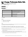
h. Enter VAF version command AT+VAFV to verify :
Command
AT+VAFV
Expected response
FM100_VAF_094_OAT210_32 Sep 28 200618:01:42
OK
Now the Fargo Maestro Value added Feature installation has been done. You can follow other chapters to use the
features.
Confidential, the whole present document is the sole property of Fargo Telecom (Asia) Ltd.
5
3. GPRS AND TCP/UDP PARAMETERS SETUP
Note: This chapter does not applicable to Fargo Maestro 20
The Automatic and AT command driven TCP/UDP connection (described in Chapter 4 and 5) requires GPRS connection
and TCP / UDP parameters setup. This chapter will describe those required setups.
3.1. GPRS Network Parameters
User need to enter the following parameters for GPRS connection:
-
Access point name (APN)
-
User name
-
Password
They are to be entered by using AT+IPGPRS command. Contact your network operator for these parameters.
3.1.1. AT+IPGPRS command
Description:
This command is used to setup GPRS network parameters for the TCP/UDP connection feature.
Command Syntax
AT+IPGPRS=<Cid>,<APN>,<UN>,<PW>
Response Syntax
+IPGPRS: <Cid>,<APN>,<UN>,<PW>
Command
AT+ IPGPRS?
AT+ IPGPRS=1,
AT+ IPGPRS =1,”INTERNET”
AT+ IPGPRS=?
Possible responses:
+IPGPRS: 1,"INTERNET","" ,””
OK
Note: show current settings
OK
Note: set Cid value to 1
OK
Note: set the PDP value to 1 and APN to “INTERNET”
+IPGPRS: (1-4),(100),(50),(50)
OK
Note: possible values
Defined Values :
<Cid>
PDP context identifier.
Note: to use with VAF TCP/UDP connection feature this value must be set to 1.
<APN>
Access point name of the GPRS network. Max 100 characters.
<UN>
User name to access the GPRS service. Max 50 characters.
<PW>
Password used to access the GPRS service. Max 50 characters.
Confidential, the whole present document is the sole property of Fargo Telecom (Asia) Ltd.
6
3.2. Activating GPRS Connection
For using AT command driven TCP/UDP connection (described in Chapter 5), you need to first activate the VAF GPRS
connection. There are two AT commands:
-
AT+CGATT
-
AT+IPCONNECT
3.2.1. AT+CGATT command
This standard AT command is to make the modem to attach to or detach GPRS network. For details please read AT
command document.
Command Syntax
AT+CGATT=<state>
Response Syntax
+CGATT: <state>
Command
AT+ CGATT?
AT+ CGATT=1
AT+ CGATT =0
Possible responses:
+CGATT: 0
OK
Note: display current status
OK
Note:GPRS attach success
OK
Note:GPRS detach success
Defined Values:
<state>
1:
attach GPRS
0:
detach GPRS.
3.2.2. AT+IPCONNECT command
This VAF AT commands is to make the modem to activate or deactivate GPRS connection . Once IPCONNECT is
success you can perform TCP/UDP connection as described on other chapters. Please read note below on using this
command.
Command Syntax
AT+IPCONNECT = <Bearer>,<Connect>
Response Syntax
+IPCONNECT: <Bearer>,<Connect>
Confidential, the whole present document is the sole property of Fargo Telecom (Asia) Ltd.
7
Command
AT+ IPCONNECT=?
AT+ IPCONNECT?
AT+IPCONNECT=1,1
AT+IPCONNECT=1,1
AT+ IPCONNECT =1,0
Possible responses:
+IPCONNECT: (0-1) , (0-1)
OK
Note: display possible values
+IPCONNECT: 1,0
OK
Note: display current status
OK
OK
OK
Note: Activate GPRS connection success
+CME ERROR: 3
Note: Activate GPRS connection fail
OK
Note: Deactivate GPRS connection success
Defined Values:
<Bearer>
0:
using GSM Bearer ( Note: do NOT use this for VAF )
1:
using GPRS Bearer.
<Connect>
0:
to stop connection
1:
to start connection.
Note: Before you making GPRS connection by this command make sure you have finished the following first:
1. Entered APN settings by AT+IPGPRS command Chapter 3.1.1)
2. Attached to GPRS network by AT+CGATT command (Chapter 3.2.1)
It is suggested after modem power up wait about 20 seconds before making GPRS connection.
3.3. TCP/UDP Parameters Setup
For using automatic or AT command driven TCP/UDP connection (described in Chapter 4 and 5), you need to first enter
the target TCP/UDP peer parameters. There are
-
AT+IPTCP
-
AT+IPUDP
-
AT+IPBUFF
-
3.3.1. AT+IPTCP command
This command specifies the TCP socket parameters and mode that to be used by automatic or AT command driven TCP
connection (described in Chapter 4 and 5).
Confidential, the whole present document is the sole property of Fargo Telecom (Asia) Ltd.
8
Command Syntax
AT+IPTCP=<port>,<mode>,<server>,<TCPTxDelay>
Response Syntax
+ IPTCP: <port>,<mode>,<server>,<TCPTxDelay>
Command
AT+ IPTCP?
AT+ IPTCP =23
AT+ IPTCP =23,”C”,202.144.111.222”,100
AT+ IPTCP =23,”S”,255.255.255.255”,100
AT+ IPTCP =?
Possible responses:
+IPTCP: 0,"S","",100
OK
Note : show current settings
OK
Note: set the TCP port to 23
OK
Note: to set the modem to connect TCP socket Client (caller)
mode
to target :address 202.144.111.222 and port 23
OK
to set the modem to wait for TCP socket connection request
(Server (listening) mode)
any calling IP address allowed, port 23
+IPTCP: (0-65535),("C","S"),(120),(0-32760)
OK
Note : possible argument
Defined Values:
<port>
The port number to be used for the TCP socket connection. Default value is 0. Valid range is 0 to 65535.
<mode>
Mode of TCP operation. Default value is “S”.
“S”
Server (Listening) mode. This configures Fargo Maestro to open a listening TCP connection on the specified
<port> . The TCP connection will be active upon getting socket connection request from the allowed remote TCP peer
(see <address>)
“C”
Client (caller) mode. This configures Fargo Maestro to request opening a TCP connection to the server with the
specified <address> and <port> .
Note: This parameter is used by Auto TCP connection (see Chapter 4) only.
<address>
The address of the TCP server (or host). Default value is empty. Legal values could be 32-bit in dotted-decimal notation
(i.e. xxx.xxx.xxx.xxx) or alphanumeric ASCII test string up to 120 characters (only if DNS is available on the GPRS
network)
Note: In “Server” (Listening) mode the modem will only accept TCP connection request for the caller with address
specified in the <address> field. Yet if the it is set to “255.255.255.255” the modem will accept request from ANY
address.
Confidential, the whole present document is the sole property of Fargo Telecom (Asia) Ltd.
9
<TCPTxDelay>
This parameter determines the time delay introduced before sending a TCP frame that has not been entirely filled with
user data. The timer is entered in milliseconds and it should be noted that a value of ‘0’ initiates the sending of a TCP
frame as soon as possible after the reception of a single character value from the host.
The default value is 100.
3.3.2. AT+IPUDP command
This command specifies the UDP socket parameters and mode that to be used by automatic or AT command driven UDP
connection (described in Chapter 4 and 5)..
Command Syntax
AT+IPUDP=<port>,<mode>,<server>,<UDPTxDelay>
Response Syntax
+ IPUDP: <port>,<mode>,<server>,<UDPTxDelay>
Command
AT+ IPUDP?
AT+ IPUDP =23
AT+ IPUDP =23,”C”,202.144.111.222”,100
AT+ IPUDP =23,”S”,255.255.255.255”,100
AT+ IPUDP=?
Possible responses:
+IPUDP: 0,"S","",100
OK
Note : show current settings
OK
Note: set the UDP port to 23
OK
Note: to set the modem to connect UDP socket Client (caller)
mode
to target :address 202.144.111.222 and port 23
OK
to set the modem to wait for UDP socket connection request
(Server (listening) mode)
any calling IP address allowed, port 23
+IPUDP: (0-65535),("C","S"),(120),(0-32760)
OK
Note : possible argument
Defined Values:
<port>
The port number to be used for the UDP socket connection. Default value is 0. Valid range is 0 to 65535.
<mode>
Mode of UDP operation. Default value is “S”.
“S”
Server (Listening) mode. This configures Fargo Maestro to open a listening UDP connection on the specified
<port> . The UDP connection will be active upon getting socket connection request from the allowed remote UDP peer
(see <address>)
“C”
Client (caller) mode. This configures Fargo Maestro to request opening a UDP connection to the server with the
specified <address> and <port> .
Note: This parameter is used by Auto UDP connection (see Chapter 4) only.
Confidential, the whole present document is the sole property of Fargo Telecom (Asia) Ltd.
10
<address>
The address of the UDP server (or host). Default value is empty. Legal values could be 32-bit in dotted-decimal notation
(i.e. xxx.xxx.xxx.xxx) or alphanumeric ASCII test string up to 120 characters (only if DNS is available on the GPRS
network)
Note: In “Server” (Listening) mode the modem will only accept UDP connection request for the caller with address
specified in the <address> field. Yet if it is set to “255.255.255.255” the modem will accept request from ANY address.
<UDPTxDelay>
This parameter determines the time delay introduced before sending a UDP frame that has not been entirely filled with
user data. The timer is entered in milliseconds and it should be noted that a value of ‘0’ initiates the sending of a UDP
frame as soon as possible after the reception of a single character value from the host.
The default value is 100.
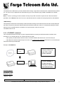
3.3.3. AT+IPBUFF command
This command specifies the number of bytes of payload data from remote peer buffered inside the modem when
automatic or AT command driven TCP / UDP connection is made.
-
If the quantity of buffered data reach this value, the whole buffered data will be sent out to the serial port.
-
If the data from remote is large enough at one time, only multiple of this value data will be sent out to the serial port
remainder will be kept inside buffer.
Example: AT+IPBUFF=5
18 bytes of data sent
from TCP or UDP
socket to modem
1234567890A
BCDEFGH
15 bytes (multiple of
5) data sent out to
serial port, remaining
data buffered inside
1234567890A
FGH
Command Syntax
AT+IPBUFF = <buff>
Response Syntax
+IPBUFF: <buff>
Command
Possible responses:
Confidential, the whole present document is the sole property of Fargo Telecom (Asia) Ltd.
11
AT+ IPBUFF=?
AT+ IPBUFF?
AT+IPBUFF = 5
+IPBUFF: 0-100
OK
Note: display possible values
+IP BUFF: 0
OK
Note: display current status
OK
Note: Set IPBUFF value to 5
Defined Values:
<buff>
The number of bytes of data to be buffered. Default value is 0 (i.e. no buffering). Valid range is 0 to 100.
Note: If the TCP or UDP socket connection is broken, buffered data will be lost.
Confidential, the whole present document is the sole property of Fargo Telecom (Asia) Ltd.
12
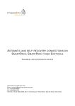
4. AUTOMATIC AND SELF-RECOVERY TCP/UDP
CONNECTION
Note: This chapter does not applicable to Fargo Maestro 20
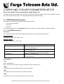
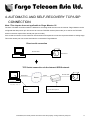
The Auto TCP/UDP connection feature is defined for accessing serial devices over the Internet. Fargo Maestro can be
configured that after power up it will connect to a remote TCP/UDP socket (client mode) or to wait for the TCP/UDP
socket connection request from remote peer (server mode).
If the socket connection is unsuccessful or disconnected it will repeat the connection request and back to waiting stage.
This make remote peer can access serial device connected to Fargo Maestro.
Direct serial connection
RS-232 cable
serial device
TCP Socket connection via the Internet /GPRS network
Broad band
RS-232 cable
GPRS
Fixed IP:
123.456.789.0
Program monitoring
Auto TCP connection set to connect
Port 23
123.456.789.0 port 23
Confidential, the whole present document is the sole property of Fargo Telecom (Asia) Ltd.
13
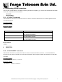
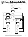
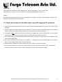
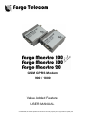
4.1. Flow diagram of Auto TCP/UDP connection function
Modem Power on/
restart
No
Is AutoTCP/UDP
enabled ?
Stop
Yes
W ait for 20 secs
No
Re-attach GPRS
No
GPRS attach OK ?
Yes
Re-activate GPRS
No
GPRS activation OK ?
Yes
TCP/UDP connection
request from allowed
peer?
No
No
Client mode ?
Yes
No
OK to open pre-defined
TCP/UDP socket ?
Dealy 2
seconds
Yes
No
Open TCP/UDP
socket, connect to
serial port
Open TCP/UDP
socket, connect to
serial port
TCP/UDP
disconnected or
closed ?
TCP/UDP
disconnected or
closed ?
Yes
Yes
GPRS attach fail ?
No
Yes
GPRS activation
fail ?
No
No
Yes
GPRS attach fail ?
Yes
No
GPRS activation
fail ?
Yes
No
Confidential, the whole present document is the sole property of Fargo Telecom (Asia) Ltd.
14
4.2. AT commands for Auto TCP/UDP connection
4.2.1. AT+AUTOTCP command
This command controls the Maestro 100/100 Lite to start TCP socket connection automatically
Before using AT+AUTOTCP TCP and GPRS settings MUST be setup properly using AT+IPTCP and AT+IPGPRS
command respectively.
Command Syntax
AT+AUTOTCP=<mode>
Response syntax:
+AUTOTCP: <mode>
Command
AT+AUTOTCP=0
AT+AUTOTCP=1
AT+ AUTOTCP?
AT+AUTOTCP=?
Possible responses:
OK
Note : disable AutoTCP
OK
Enable AutoTCP
+AUTOTCP : 1
OK
Note display current status
+AUTOTCP : (0-1)
Note : possible argument
Defined Values:
<mode>
1
enable auto TCP
0
disable auto TCP
Note :
-
Before enabling Auto TCP, it MUST be properly set the GPRS settings by AT+IPGPRS command and TCP settings
by AT+IPTCP command (see Chapter 3)
-
ONLY GPRS PDP context # 1 will be used. So please setup +IPGPRS settings with <cid>=1
-
Once AutoTCP is enabled, it will start the TCP socket connection automatically after 20 seconds.
-
Once the TCP connection is established successfully, the serial port will go to data mode, all data entered to the serial
port will be sent to remote TCP peer. No more AT commands will be accepted then.
-
In TCP connected data mode, the DSR and DCD signals of the serial port will go to high.
-
If the TCP connection is broken the modem will try to reconnect automatically. During re-connection period serial port
will go back to command mode, and DSR/DCD signal back to low.
-
The setting will be saved, and after power off, the AUTOTCP will be restarted with the 20 seconds delay after power
up.
-
To stop auto TCP connection, you need to enter the command AT+AUTOTCP=0 by either 1: within 20 seconds after
power up, or 2: during reconnection (serial port back to command mode), or 3: by SMS (see Chapter , SMS AT
command).
-
Auto TCP connection is exclusive to other TCP/UDP feature. See Chapter 10 (Q&A)
Confidential, the whole present document is the sole property of Fargo Telecom (Asia) Ltd.
15
4.2.2. AT+AUTOUDP command
This command controls the Maestro 100/100 Lite to start UDPacket connection automatically.
Before using AT+AUTOUDP TCP and GPRS settings MUST be setup properly using AT+IPUDP and AT+IPGPRS
command respectively.
Command Syntax
AT+AUTOUDP=<mode>
Response syntax:
+AUTOUDP: <mode>
Command
AT+AUTOUDP=0
AT+AUTOUDP=1
AT+ AUTOUDP?
AT+AUTOUDP=?
Possible responses:
OK
Note : disable AutoUDP
OK
Note: Enable AutoUDP
+AUTOUDP : 1
OK
Note: display current status
+AUTOUDP : (0-1)
Note : possible argument
Defined Values:
<mode>
1
enable auto UDP
0
disable auto UDP
Note :
-
Before enabling Auto UDP, it MUST be properly set the GPRS settings by AT+IPGPRS command and UDP settings
by AT+IPUDP command
-
ONLY GPRS PDP context # 1 will be used. So please setup +IPGPRS settings with <cid>=1
-
Once AutoUDP is enabled, it will start the UDP socket connection automatically after 20 seconds.
-
Once the UDP connection is established successfully, the serial port will go to data mode, all data entered to the
serial port will be sent to remote UDP peer. No more AT commands will be accepted then.
-
In UDP connected data mode, the DSR and DCD signals of the serial port will go to high.
-
If the UDP connection is broken the modem will try to reconnect automatically. During re-connection period serial port
will go back to command mode, and DSR/DCD signal back to low.
-
The setting will be saved, and after power off, the AUTOUDP will be restarted with the 20 seconds delay after power
up.
-
To stop auto UDP connection, you need to enter the command AT+AUTOUDP=0 by 1: within 20 seconds after
power up, or 2: during reconnection (serial port back to command mode) or 3: by SMS (see Chapter , SMS AT
command).
-
Auto TCP connection is exclusive to other TCP/UDP feature. See Chapter 10 (Q&A)
Confidential, the whole present document is the sole property of Fargo Telecom (Asia) Ltd.
16
-
Due to the nature of UDP socket connection, AT+AUTOUDP=0 may not be able to disconnection. in this case you
may send command AT+IPCONNECT=1,0 to disconnect GPRS connection.
Confidential, the whole present document is the sole property of Fargo Telecom (Asia) Ltd.
17
5. AT COMMAND DRIVEN TCP/UDP CONNECTION
Note: This chapter does not applicable to Fargo Maestro 20
This feature let user to make a TCP or UDP connection upon the AT+OTCP or AT+OUDP command.
This socket connection feature do support DLE/ETX character coding. See
The AT+OTCP and AT+OUDP operation is similar to AT#OTCP and AT#OUDP function provided original IP Connectivity.
See IP connectivity document.
Make sure you have made the GPRS connection by AT+IPCONNECT command before making socket connection (see
Chapter 11, setup examples).
5.1. AT commands for Auto TCP/UDP connection
5.1.1. AT+DLEMODE command
When performing the AT command driven TCP or UDP socket connection, the attached host has the choice to code or
not the ETX character.
When DLEMODE is set to 0, no specific process is needed on ETX characters. It means that it is not possible for a host
to request a end of connection or to receive a clear indication of end of connection from the TCP/IP stack.
When DLEMODE is set to 1, the ETX character means a request or an indication of end of connection.
As a consequence, ETX characters that belongs to the payload data must be sent by the host on the serial port preceded
by a DLE
character. Similarly ETX characters received by the TCP/IP stack from the Internet are sent to the host through the serial
port preceded by a DLE character
“ETX” is character hex 03, “DLE” character is hex 10 (Dec 16)
Default value is 0.
Command Syntax
AT+DLEMODE=<mode>
Response syntax:
+DLEMODE: <mode>
Command
AT+ DLEMODE =0
AT+ DLEMODE =1
AT+ DLEMODE?
AT+ DLEMODE =?
Possible responses:
OK
Note : disable DLEMODE
OK
Note: Enable DLEMODE
+DLEMODE : 1
OK
Note: display current status
+DELMODE : (0-1)
Note : possible argument
Confidential, the whole present document is the sole property of Fargo Telecom (Asia) Ltd.
18
Defined Values:
<mode>
1
enable DLEMODE
0
disable DLEMODE
Note :
-
DLEMODE is not available for Automatic TCP/UDP connection.
5.1.2. AT+OTCP command
This command sent by the attached host to open a TCP connection to the TCP server specified by the AT+IPCTP
command. If socket connection is made successfully it will response CONNECT 115200 and the serial port will go to data
mode, all data entered to the serial port will be sent to remote TCP/UDP peer.
If socket connection is unsuccessful or socket is disconnected afterwards the modem will send out NO CARRIER
message and back to command mode.
Command Syntax
AT+OTCP
Response syntax:
CONNECT 115200
Command
AT+ OTCP
Possible responses:
CONNECT 115200
Note : TCP connection made successfully
+CME ERROR 3
Note: fail, either IPCONNECT is not ready or socket service
is used already
NO CARRIER
Note: possibly remote server no response
AT+ OTCP
AT+ OTCP
Note :
-
AT+OTCP connection is exclusive to other TCP feature. See Chapter (Q&A)
-
If TCP connection is unsuccessful or broken after connection the GPRS connection will also be disconnected.
(+IPCONNECT: 1,0). So please enter AT+IPCONNECT=1,1 to reconnect GPRS before entering AT+OTCP.
5.1.3. AT+OUDP command
This command sent by the attached host to open a UDP connection to the UDP server specified by the AT+IPUDP
command. If socket connection is made successfully it will response CONNECT 115200 and the serial port will go to data
mode, all data entered to the serial port will be sent to remote UDP peer.
If socket connection is unsuccessful or socket is disconnected afterwards the modem will send out NO CARRIER
message and back to command mode.
Confidential, the whole present document is the sole property of Fargo Telecom (Asia) Ltd.
19
Command Syntax
AT+OTCP
Response syntax:
CONNECT 115200
Command
AT+ OUDP
Possible responses:
CONNECT 115200
Note : UDP connection made successfully
+CME ERROR 3
Note: fail, either IPCONNECT is not ready or socket service
is used already
NO CARRIER
Note: possibly remote server no response
AT+ OUDP
AT+ OUDP
Note :
-
AT+OUDP connection is exclusive to other TCP/UDP feature. See Chapter (Q&A)
-
If UDP connection is unsuccessful or broken after connection the GPRS connection will also be disconnected.
(+IPCONNECT: 1,0). So please enter AT+IPCONNECT=1,1 to reconnect GPRS before entering AT+OUDP.
-
Due to the nature of UDP socket connection, sending ETX characters (when DLEMODE is 1)may not be able to
make disconnection.
Confidential, the whole present document is the sole property of Fargo Telecom (Asia) Ltd.
20
6. REMOTE AT COMMAND BY SMS
This feature is to control the modem to interpret AT command from incoming SMS, executing it, and return the result to
sender by SMS.
The user can enable the modem to receive AT command by incoming SMS. See following about AT+SMSAT command.
6.1. Description of the Operation
Step 1 : send AT command to
modem by SMS
000000AT+CSQ
Step 2 : modem execute and
return response by SMS
+CSQ: 17,0 OK
1. When enabled, the modem will treat the incoming SMS as a source of AT command only if all of the following
conditions (a,b and c) are fulfilled :
a. The content of SMS sent to the modem is using standard 7-bit GSM data decoding scheme,
b. The first 6 characters of the SMS content matches the <key> parameter set by AT+SMSAT command, (default key
is “000000”)
c. The 7th and 8th characters of the SMS content is “AT” (in capital letters)
2. If SMSAT is enabled , the modem will read each incoming SMS, if the conditions mentioned in 1 are matched the
message will be executed, even it is an invalid AT command
3. When using SMSAT feature, only +CNMI:x,1,x,x,x setting could be used (i.e. incoming message will be stored in SIM
card).
4. The maximum length of the AT command is limited by length of SMS, i.e. 160-6 = 154 characters
5. When the SMS AT command is executed , all intermediate and final responses will be buffered recorded, then return to
the sender’s phone number in one single SMS.
6. If response(s) of the AT command is(are) more than 160 characters, only the first 160 characters will be returned.
7. In case the modem cannot get terminal response within 26 seconds, the modem will then abort the command, and
return intermediate responses (if present).
8. If the SMSAT feature is enabled, all incoming SMS, either with valid AT command or not, will be erased. This is to
prevent SIM card memory from fully filled, such the modem will not receive new SMS.
Confidential, the whole present document is the sole property of Fargo Telecom (Asia) Ltd.
21
6.2. AT command for configuring AT command
6.2.1. AT+SMSAT command
Command Syntax
AT+SMSAT=<mode>(,<key>)
Response syntax:
+SMSAT: <mode>,<key>
Command
AT+SMSAT=0
AT+ SMSAT =1
AT+ SMSAT?
AT+SMSAT=2,123456
AT+ SMSAT =?
Possible responses:
OK
Note : disable remote AT command by SMS
OK
Enable remote AT command by SMS
+SMSAT : 1,000000
OK
Note display current status
OK
Note: set the <key> value
+SMSAT : (0-2),(6)
OK
Note : possible argument
Defined Values:
<mode>
0
disable remote AT command by SMS
1
enable remote AT command by SMS
2
change the value of the <key>
<key>
A 6-digit numeric character key from 000000 to 999999. Only incoming SMS with the first 6 characters matching with this
key will be treated as a valid source of remote AT command.
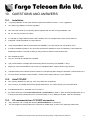
6.3. Limitation and caution to be taken when using remote AT command
This feature will not ‘judge’ the result of executing the command, so care has to be taken not to enter improper command
that make the modem becoming out of control:
1.
Never send ‘interactive’ AT command by SMS, e.g. AT+CMGS=…. This feature cannot return the prompt to the
sender for second input
2. Always wait for the return SMS with AT responses before you send another SMS AT command.
3. It could be in some case (e.g. network failure) the modem cannot return response SMS. The modem will try sending
response SMS for three times max. If still not successful it will abort.
Confidential, the whole present document is the sole property of Fargo Telecom (Asia) Ltd.
22
4. Always think twice before you send AT command by SMS. For example if you send AT+CPOF it will turn off the
modem, and you need to go to access the modem to reset it.
5. Some VAF AT commands can be sent over SMS. See Chapter
Confidential, the whole present document is the sole property of Fargo Telecom (Asia) Ltd.
23
7. I/O TRIGGERED AT COMMAND
This feature making use of the Fargo Maestro Input/Output port as a sensor. If the signal to the port match the pre-defined
condition a stored AT command will be executed.
User can use AT+IOAT command to set the condition and store AT command to be executed.
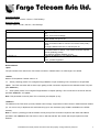
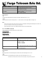
7.1. Description of the Operation
I/O port
Wiring Diagram :
1. When the I/O port is connected to high 3V signal,
Switch closed : logic level high
Switch opened : logic level low.
2. The switch can be placed as a triggering device, e.g. to detect door opening.
3. According to the setting of AT+IOAT command, the stored AT command will be executed either I/O signal from high to
low, or from low to high :
When set as low-to-high triggering:
Start counting time when a
when period of high signal
low to high signal
reach the Threshold value
I/O port voltage
time = T
Confidential, the whole present document is the sole property of Fargo Telecom (Asia) Ltd.
24
When set as high-to-low triggering :
I/O port voltage
time = T
Start counting time when a
when period of low signal
high to low signal
reach Threshold value the
* See AT+IOAT command on setting Threshold value T.
7.2. AT command for configuring I/O triggered AT command
7.2.1. AT+IOAT command
Command Syntax
AT+IOAT=<action>(,<dir>,<Threshold>,<cmd> )
Response syntax:
+SMSAT: <action>,<dir>,<Threshold>,<cmd>
Command
AT+IOAT=0
AT+IOAT =1
AT+ IOAT?
AT+IOAT=2,1,10,”AT+IPR=115200”
AT+ IOAT =?
Possible responses:
OK
Note : disable I/O triggered AT command execution
OK
Enable remote I/O triggered AT command execution
+IOAT : 1,1, 10,”AT+CMSS=5”
OK
Note display current status
OK
Note: set the parameters < dir>, <Threshold>, <cmd>
low-to-high triggering, Threshold=1000 ms
command is “AT+IPR=115200”
+IOAT : (0-2),(0-1),(1-50),(128)
OK
Note : possible argument
Defined Values:
<action>
0
disable I/O triggered AT command execution
1
enable I/O triggered AT command execution
2
configure I/O triggered AT command parameters
<dir>
0
configure as low-to-high triggering
1
configure as high-to-low triggering
Confidential, the whole present document is the sole property of Fargo Telecom (Asia) Ltd.
25
<Threshold>
Time required for the detected state to trigger the AT command exestuation. Unit is in millisecond.
Valid value from 1 to 50 (0.1 sec to 5 sec). Refer to the above timing diagram in section 5.1.
<cmd>
AT command to be executed when the I/O port is triggered successfully. The length of the command is limited to 128
characters. See section 5.3 for more details.
7.3. Notes and cautions to be taken when using I/O triggered AT command
1. The I/O port is limited to drain current 10mA max. Never give too high input voltage to the I/O port or the modem will be
damaged.
2. Use only cable/metal contact designed for Molex MicroFit™ connector. Using incompatible connector will damage the
modem. Contact your dealer or Fargo Telecom if you need wire for the I/O port connection.
3. The modem will NOT check the command you entered to the <cmd> field. It will be executed even it is not a valid AT
command (or even not an AT command). Check by yourself when you enter the command.
4. When triggered, the command will be executed in ‘quiet’ mode, i.e. without any response like “OK” or “ERROR” will be
sent to external application.
5. Do not enter “interactive” AT command (e.g. AT+CMGS=…), otherwise when the command is executed, the modem
will in a state of waiting further input, not to do other jobs.
6. With this feature enabled user cannot control the I/O port by other AT commands anymore.
7. Due to product limitation the modem cannot detect switching action with period less than 100ms. If the switch’s
open/close action is done in less than 100ms this feature will not be able to detect accurately.
Confidential, the whole present document is the sole property of Fargo Telecom (Asia) Ltd.
26
8. CALL SCREENING
This feature enable the Fargo Maestro to reject incoming call if the phone number does not match one of the entries of
authorized phone number list. Unauthorized incoming call will be hanged up within one ring.
Up to 10 authorized phone numbers can be stored. Each number can be as long as characters
Waiting call can also be rejected.
8.1. AT command for configuring call screening
8.1.1. AT+CSRN command
This command is to enable or disable call screening feature.
Command Syntax:
AT+CSRN=<mode>
Response syntax:
+CSRN: <mode>
Command
AT+CSRN=0
Possible responses:
OK
Note : disable call screening
OK
Enable call screening
+CSRN : 1
Note display current status
+CSRN: (0-1)
Note : possible argument
AT+CSRN=1
AT+CSRN?
AT+CSRN=?
Defined Values :
<mode>
0
disable call screening
1
enable call screening
Note :
-
To use call screening make sure Caller ID service is enabled otherwise all incoming call will be rejected.
-
To apply call screening to waiting call please first enable Call waiting indication by command AT=CCWA=1,1
-
Rejected incoming will not be diverted to voice mail.
8.1.2. AT+CSNW command
This command is to enter authorized phone number.
Command Syntax:
AT+CSNW=<id>,<num>
Response syntax:
OK
Confidential, the whole present document is the sole property of Fargo Telecom (Asia) Ltd.
27
Command
AT+CSNW=1,”12345678”
AT+CSNW=11,”12345678”
AT+CSNW=3,”1qaaa”
AT+CSNW=?
Possible responses:
OK
Note : enter authorized number to location 1
+CME ERROR: 3
Note : location out of range
+CME ERROR: 3
Note : non-numeric characters not allowed
+CSRN: (1-10),(20)
Note : possible argument
Defined Values :
<id>
Location of the authorized phone number to be stored. Valid range is from 1 to 10
<num>
Authorized phone number. First digit can be “+”, others must be numeric digits. Maximum length is 20
Note :
-
Enter phone number exactly same as the incoming one, especially if entering International phone number. Use
AT+CLIP command to check incoming call number first.
-
Enter empty phone number in the <num> field will erase the record of that location.
8.1.3. AT+CSNR command
This command is to read authorized phone number entered.
Command Syntax:
AT+CSNR=<id1>(,<id2>)
Response syntax:
+CSNR: <id>,<num>….
Command
AT+CSNR=1
Possible responses:
+CSNR: 1, “12345678”
OK
Note : display authorized number in location 1
+CSNR: 1, “12345678”
+CSNR: 3, “123456”
+CSNR: 6, “12345678”
+CSNR: 8, “12345678”
AT+CSNR=1,8
OK
Note : display authorized number in from location 1 to 8
+CSNR=(1-10),(1-10)
OK
Note: possible argument
AT+CSNR=?
Defined Values :
<id1>
Beginning location of the authorized phone number to be read. Valid range is from 1 to 10.
<id2>
Ending location of the authorized phone number to be read. Valid range is from 1 to 10.
Confidential, the whole present document is the sole property of Fargo Telecom (Asia) Ltd.
28
8.1.4. AT+CSND command
This command is to erase authorized phone number entered.
Command Syntax:
AT+CSND=<id1>(,<id2>)
Response syntax:
+CSNR: <id>,<num>….
Command
AT+CSND=1
Possible responses:
OK
Note : erase authorized number in location 1
OK
Note : erase authorized number in from location 1 to 8
+CSND=(1-10),(1-10)
OK
Note: possible argument
AT+CSNR=1,8
AT+CSND=?
Defined Values :
<id1>
Beginning location of the authorized phone number to be erased. Valid range is from 1 to 10.
<id2>
Ending location of the authorized phone number to be erased. Valid range is from 1 to 10.
Confidential, the whole present document is the sole property of Fargo Telecom (Asia) Ltd.
29
9. KNOWN ISSUES
The Fargo Maestro Value Added Feature will affect certain other AT commands operation. Please note.
:
9.1. AT+WIND command
AT+WIND command will be disabled (Fargo Maestro 100 only)
9.2. Saving of parameters to non-volatile memory
You cannot save the settings of the following AT commands by concatenating the &W command (Fargo
Maestro 100 only):
AT+CREG
AT+CGREG
AT+CGEREP
To save the above settings please enter AT&W separately.
9.3. Mutually exclusive TCP/UDP functions.
Following functions are exclusive to each other, i.e. if either is enabled others could not be then:
AT+AUTOTCP=1
AT+AUTOUDP=1
AT+OTCP
AT+OUDP
9.4. Sending VAF AT commands over SMS
You can use the remote AT command by SMS feature to send VAF AT commands mentioned in this document except
the followings:
AT+OTCP
AT+OUDP
AT+IPCONNECT
Confidential, the whole present document is the sole property of Fargo Telecom (Asia) Ltd.
30
10. QUESTIONS AND ANSWERS
10.1.
Installation
Q.
If my Fargo Maestro cannot match with the requirement stated in section 2.1, can I upgrade it?
A.
No. Older Fargo Maestro cannot be upgraded.
Q.
Can I have the TCP/IP (IP connectivity) feature together with this VAF for Fargo Maestro 100?
A.
No. You can only choose one of them.
Q.
If I changed my Fargo Maestro with the VAF installed, can it be changed back to have TCP/IP feature?
A.
It depends. Contact Distributor or Fargo Telecom
Q.
I have downloaded the dwl file, and entered AT+WOPEN=1, but I still cannot use VAF features, why ?
A.
It could be installation problem. You can issue command AT+WOPEN=0, then AT+WOPEN=4, then repeat the
download procedure. If this still not help you may need to re-flash the main firmware first.
Q.
Can I disable the VAF ?
A.
Yes, you can enter AT+WOPEN=0 to disable.
Q.
I get “Invalid modem” message after downloading dwl file and issuing AT+WOPEN=1. Why ?
A.
Maybe you have downloaded file into incorrect or damaged modem. Please contact Fargo Telecom.
Q.
I had download incorrect dwl file, and the modem is not responding after issuing AT+WOPEN=1. What should I do ?
A.
You may need to re-flash the main firmware. Please contact Fargo Telecom or your distributor.
10.2.
AutoTCP/UDP
Q.
Can I specify <server> by URL (e.g. xxxx.com) rather than IP address?
A.
Yes, but only if your GPRS network have proper DNS service. You cannot specify your own DNS server
Q.
If I enabled AutoTCP or AutoUDP, how can I stop it ?
A. you need to enter the command AT+AUTOTCP=0 or AUTOUDP=0 by either 1: within 20 seconds after power up, or
2: during reconnection (serial port back to command mode), or 3: by SMS (see Chapter , SMS AT command).
10.3.
AT command driven TCP/UDP connection
Q.
Why I see three “OK” coming after entering AT+IPCONNECT=1,1 command ?
A.
The VAF program is issuing internal AT command for GPRS setup, so extra “OK” responses will be seen.
Confidential, the whole present document is the sole property of Fargo Telecom (Asia) Ltd.
31
Q.
After the TCP/UDP connection is stopped I wan to enter AT+OTCP or AT+OUDP to reconnect but I get message
“+CME ERROR: 3”. Why ?
A.
After TCP/UDP socket connection the GPRS connection session will also be disconnected. So please enter
AT+IPCONNECT=1,1 to reconnect GPRS first.
10.4.
Remote AT command by SMS
Q.
Can I send any AT command by SMS to control other features described in this document?
A.
Yes. Please refer to Chapter 9.4.
10.5.
I/O triggered AT command
Q.
Can I put any AT command to control other features described in this document?
A.
No. VAF AT commands described in this document cannot be executed by this feature.
Confidential, the whole present document is the sole property of Fargo Telecom (Asia) Ltd.
32
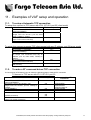
11. Examples of VAF setup and operation
11.1.
To setup a Automatic TCP connection
To setup Auto connect to TCP server with IP 61.167.60.1 port 23 (client mode)
Commands to be entered
Modem response
AT+IPGPRS=1,”INTERNET”
(APN is INTERNET)
AT+IPCTP = 23,”C”,”61.167.60.1”,100
(target TCP is 61.167.60.1, port 23, client
mode, TxDelay is 100ms)
AT+AUTOTCP=1
(open TCP socket connection)
(TCP connection will start after 20 secs)
OK
OK
OK
To setup Auto connect to remote TCP client request with any IP address, port 23(server mode)
11.2.
Commands to be entered
Modem response
AT+IPGPRS=1,”INTERNET”
(APN is INTERNET)
AT+IPCTP = 23,”C”,”255.255.255.255”, 100
(to accept TCP connection from any IP
address, port 23, client mode, TxDelay is
100ms)
AT+AUTOTCP=1
(open TCP socket connection)
(Modem will start to monitor TCP port 23
after 20 secs)
OK
OK
OK
To make a AT command driven TCP connection
IP Connectivity (AT# feature) user can follow the following steps to make OCTP connection
To connect to TCP server with IP 61.167.60.1 port 23
Commands to be entered
Modem response
AT+IPGPRS=1,”INTERNET”
(APN is INTERNET)
AT+IPCTP = 23,”C”,”61.167.60.1”,100
(target TCP is 61.167.60.1, port 23, TxDelay is
100ms)
AT+DLEMODE=1
AT+CGATT=1
AT+IPCONNECT=1,1
OK
AT#APNSERV
OK
AT#TCPSERV
AT#TCPPORT
AT#TCPTXDELAY
AT#DLEMODE
AT+CGATT=1
AT#CONNECTIONSTART
(GPRS connection)
AT+OCTP
(open TCP socket connection)
OK
OK
OK
OK
OK
CONNECT 115200
Corresponding AT#
command
AT#OCTP
Confidential, the whole present document is the sole property of Fargo Telecom (Asia) Ltd.
33