1
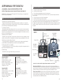
USER MANUAL FOR T4EU&T4U
4-CHANNEL 2.4GHz RADIO CONTROL SYSTEM
INSTRUCTION MANUAL FOR R/C HELICOPTER AND AIRPLANE USE
RADIOLINK 4CH 2.4GHz transmitter T4EU adopts FHSS 2.4GHz technology, it is compatible with
both helicopter and airplane mode.
FEATURES (T4EU-2.4GHz Version):
1) Transmitter hops spectrum while powering on
Transmitter detects whether the current spectrum channel was occupied or not, if occupied it
would hop to next channel till hop to a channel with rest; The receiver searches a transmitter with
the same identity code and match with the transmitter.
QUICK REFERENCE GUIDE:
1. Charge the transmitter and receiver batteries.
2. Connect servos to the receiver.
3. Turn on the transmitter and then turn on the receiver power.
4. Center all four transmitter trim levers. Make sure all servos operate according to transmitter
stick movements.
5. Turn off the system, receiver first, then transmitter.
6. Install the entire radio system into your model.
7. If you need to reverse the direction in which a servo rotates, locate the reversing switch for the
desired channel on the bottom front of the transmitter and slide it to the “REVERSE” position.
8. Range test the radio system prior to flight. With the transmitter antenna collapsed, you should
be able to smoothly control movement of all control surfaces on your model from at least 100ft on
the ground.
2) Code matches wirelessly
Each transmitter has an unique identity code of its own, receiver searches the nearest transmitter
and bind transmitter's identity with itself when you press the code matching button on the receiver
and get it into code matching mode. There is no need to match again in future without reference to
power on or off after matching success.
THE TRANSMITTER AND RECEIVER:
MODE1
3) High anti-interference capability
CH4:Rudder
Ch3: Throttle
Power LED
Adopt FHSS technology to make our product have excellent anti-interference capability, our radio
can keep out the interference from equipments in the same frequency, and always be in the control.
4) High Suppression Ratio of Adjacent Channels.
RIGHT GIMBAL
Atenna
Elevator Trim
Throttle Trim
Simulator
Connector
Our system has at least 60 signal channels, the suppression ratio of adjacent signal channels is
more than 60DB, so that the flight will get no interference from adjacent channels.
LEFT GIMBAL
5) Totally comply with FCC & CE standards.
Our product has obtained FCC & CE certificates, and they can beyond the testing requirements for
big volume order totally and completely.
CH1:Aileron
Ch2: Elevator
Aileron Trim
6) Stable RF range
With the FHSS technology the radio’s RF range can reach 900M.
Servo Reverse
Switch
SPECIFICATION:
Transmitter(T4EU)
Channels: 4-channel
Transmitting frequencies: 2.4GHz
Modulation type: 2.4GHz FHSS
Nominal current drain: approx. 100mA
Input power: 9.6V NiCd battery
Output power: <0.01W
Receiver(R6F)
Channels: 6-channel
Receiving frequencies: 2.4GHz
Input power: 4.8V or 6.0V NiCd battery
Receiving Range: 500 yards ground, 1000
yards air
Transmitter(T4U)
Channels: 4-channel
Transmitting frequencies: 35,40 or 72MHz
Modulation type: PPM
Nominal current drain: approx. 100mA
Input power: 9.6V NiCd battery
Output power: <50mW
Receiver(R6H)
Channels: 6-channel
Receiving frequencies: 35,40 or 72MHz
Input power: 4.8V or 6.0V NiCd battery
Receiving Range: 500 yards ground, 1000
yards air
1
Power Switch
Rudder Trim
Elevon Mixing
Switch
Operation of controls and their assigned channel numbers are as follows:
Aileron Control (CH1): When the aileron stick is moved to the right, the right aileron is
raised and the left aileron is lowered and the plane banks to the right. When the aileron stick is
moved to the left, the ailerons move in the opposite direction and the airplane banks left. To level
the plane, the aileron stick must be moved in the opposite direction and back to center
.
Elevator Control (CH2): When the elevator stick is pulled back, the tail elevator is raised and
the tail of the plane is forced down, thus causing the plane to climb (UP operation). When the
elevator stick is pushed forward, the elevator is lowered; the tail of the plane is forced up, thus
causing the plane to descend (DOWN operation).
2
Throttle Control (CH3): When the throttle stick is pulled back, the engine throttle lever arm moves
to the SLOW (low speed) side. When the throttle stick is pushed forward, the throttle lever arm
moves to the HIGH (high speed) side.
Rudder Control (CH4):When the rudder stick is moved to the right, the rudder moves to the right
and the nose points to the right, thus causing the plane to turn right. When the rudder stick is
moved to the left, the rudder moves to the left and the nose points to the left, thus causing the plane
to turn left.
*Always fully charge the Tx and Rx NiCd batteries before each flight. Failure to do so could cause an
inadvertent power failure and a crash.
*Do not leave the radio system, batteries, model airplane or other modeling equipment within the
reach of children.
*Do not overheat or throw the NiCd batteries into a fire. Leaking electrolyte from the battery
could cause injury, such as burns or blindness. IN CASE OF EMERGENCY, IMMEDIATELY FLUSH
YOUR EYES, SKIN OR CLOTHES WITH PLENTY OF WATER AND SEE A DOCTOR.
Servo Reverse Switch (all) : Used to reverse the servo for all 4 channel.
Power switch : Used to turn on the transmitter.
Battery level indicator(LED) : When the LED flashes, you should stop
using the transmitter and replace the transmitter batteries.
Trimer(All): Used to trim the neutral position of all 4 channel.
Elevon Mixing switch : Used to turn on /off the Elevon mixing function.
Intended for tailless, “flying wing” models such as delta wings and flying
wings, elevon mixing mixes channel 1 (aileron) to channel 2 (elevator)
allowing the elevons to operate in unison (as elevators) or in opposition
(as ailerons). This function requires that each elevon be operated by a
separate servo.
Connect the servos to the receiver to perform the functions indicated:
SYNCHRONISING A NEW TRANSMITTER/RECEIVER( FOR T4EU ONLY):
If you replace the receiver or transmitter for your Helicopter, you will need to re-establish a link
between the two units by synching them, which is a very straightforward procedure.
To synchronize you should do the following:
1. Remove the canopy so that you can access the receiver
2. Switch on the transmitter, ensuring that the helicopter is in
Normal but not Idle up mode. and then put the throttle control
stick is at its lowest position
3. Connect the Li-Po battery to the helicopter and wait until
the LED on the receiver glows solid
4. Whilst holding the helicopter tightly, press and hold the
switch (see illustration) on the receiver Unit for approximately
5 seconds until you here the servos in the helicopter twitch this signifies that the helicopter and transmitter are now
synchronized and you can fly normally.
SYNCHRONISING KEY
TRANSMITTER MODE CONVERSION:
NOTE: The default setting for the transmitter is Mode 2, throttle left.
Step 1
To convert the transmitter from Mode 2 to Mode 1,
you need to remove the 8 AA batteries, then remove
the back of the transmitter case.
Locate the Mode Reverse Switch on the surface of the
PCB and carefully move the switch to its lower position
to change to Mode 1.
WARNING:
*Do not fly simultaneously on a frequency that is already being used in your area.
*Doing so could cause unwanted interference, a crash and possibly bodily harm.
*Do not fly in the rain or at night. Water can permanently damage many of the components in the
radio system, possibly causing loss of control and a crash.
*Only fly at designated R/C flying fields. Fly at safe distances away from other people, objects in the
air, buildings, electrical lines, or any other object which could possibly impede safe flying. Failure to
do so could cause a crash and possibly bodily harm and physical damage to other property.
*During flight preparations, be certain to place the Tx on its back when on the ground, to prevent it
from accidentally falling over and inadvertently moving the throttle stick to high speed.
*Do not allow fuel or oil on the plastic parts. Some plastics may melt when exposed to such materials.
*BEFORE turning the Tx's power switch “ON”, adjust the throttle stick to minimum speed position.
After stopping the engine turn “OFF” the Rx's power switch, then turn “OFF” the Tx power switch
Failure to follow this order could cause the engine to go to full throttle and cause an injury.
*Do not make adjustments to the radio system while the engine is running unless absolutely
necessary. Failure to do so could cause the engine to accidentally go to high speed and cause an injury.
3
Step 2
Loosen the screws to take off the spring and ratchet
and exchange their position and watch carefully the
new position of the spring and ratchet.
Tips: When you install the spring to its new position,
please attach the spring to the spring hook before
installing the arm.
Step 3
Change the Throttle and Elevator reverse switch
positions. The mode conversion is finished.
Test the hobby’s flight performance and adjust the trims
as necessary.
4