1
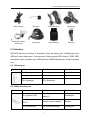
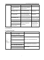
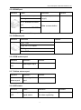
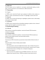
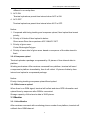
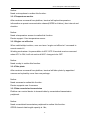
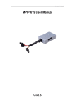
China Aerospace Telecommunications Ltd
SAT803 User Manual
C h i n a A e r o s p a c e Te l e c o m m u n i c a t i o n s L i m i t e d
1
China Aerospace Telecommunications Ltd
Content
1. Introduction ....................................................................................................................... 4
2. Overview ........................................................................................................................... 4
2.1 Main Unit ..................................................................................................................... 4
2.2 Accessories ................................................................................................................. 5
2.3 Interface ...................................................................................................................... 6
2.3.1 Power port ............................................................................................................ 6
2.3.2 Multi function port ................................................................................................. 6
2.3.3 Hand shank port ................................................................................................... 7
2.3.4 RS485 port ........................................................................................................... 8
2.3.5 G-Mouse port ....................................................................................................... 8
2.3.6 GSM antenna port ................................................................................................ 8
2.3.7 Iridium antenna port .............................................................................................. 8
2.3.8 LED status ............................................................................................................ 8
3. Function ...........................................................................................................................10
3.1 Connection .................................................................................................................10
3.1.1 Log in ..................................................................................................................10
3.1.2 Log out ................................................................................................................10
3.1.3 Heartbeat ............................................................................................................10
3.2 Positioning& Tracking .................................................................................................10
3.2.1 Roll call................................................................................................................10
3.2.2 Timing tracking ....................................................................................................10
3.2.3 Fixed upload ........................................................................................................10
3.2.4 Compress upload ................................................................................................ 11
3.2.5 Blind area re-upload ............................................................................................ 11
3.3 Monitor ....................................................................................................................... 11
3.3.1 Voice Monitor....................................................................................................... 11
3.3.2 Temperature monitor ...........................................................................................12
3.3.3 Engine cut off/revive ............................................................................................12
3.3.4 Take photo ...........................................................................................................12
3.3.5 Data unvarnished transmission............................................................................12
3.4 Alarm ..........................................................................................................................13
3.4.1 Speeding .............................................................................................................13
3.4.2 SOS.....................................................................................................................13
3.4.3 ACC status change ..............................................................................................13
3.5 Remote maintenance .................................................................................................13
2
China Aerospace Telecommunications Ltd
3.5.1 Remote reset .......................................................................................................13
3.5.2 Remote initialization ............................................................................................13
3.5.3 Remote upgrade ..................................................................................................13
3.5.4 Remote set/read parameters ...............................................................................13
3.5.5 SMS set/read parameters ....................................................................................13
3.6 Local maintenance .....................................................................................................14
4. Installation ........................................................................................................................15
4.1 SIM card .....................................................................................................................15
4.2 Cable connection ........................................................................................................15
4.3 Main unit.....................................................................................................................19
4.4 G-MOUSE ..................................................................................................................20
4.5 GSM antenna .............................................................................................................20
4.6 Iridium antenna...........................................................................................................20
4.7 SOS button .................................................................................................................21
4.8 Relay ..........................................................................................................................21
4.9 Finish Installation ........................................................................................................22
5 Specification ......................................................................................................................23
5.1 Electronic ...................................................................................................................23
5.2 Iridium ........................................................................................................................23
5.3 GSM ...........................................................................................................................23
5.4 GPS ...........................................................................................................................24
5.5 Environment ...............................................................................................................25
5.6 Machinery ...................................................................................................................25
6
Maintenance.................................................................................................................26
7. Trouble shooting ...............................................................................................................28
8. Claim ................................................................................................................................31
3
China Aerospace Telecommunications Ltd
1. Introduction
SAT-803 is a global GPS tracker with two communication modes(GPRS& Iridium),
and it can choose them intelligently based on GPRS network’s signal condition,
which can both guarantee the communication and reduce the cost.
Iridium network can guarantee the data communication anywhere avoid influence
of weather, elevation, ionized stratum and distance. It specially suits for marine
affairs, aviation, remote area’s vehicle and unattended station.
SAT-803 has structure of MCU+GPRS module G610+Iridium9602+G-Mouse. It is
made up of main unit, G-Mouse, Iridium antenna, GSM antenna, power cable and
relative optional accessories.
2. Overview
2.1 Main Unit
Front View
4
China Aerospace Telecommunications Ltd
Rear View
2.2 Accessories
Power cable(s)
Fuse(s)
Multi function cable(o)
Iridium antenna(s)
GSM antenna(s)
G-Mouse(s)
Ribbon(s)
Magic tape(s)
CD(s)
SOS cable(o)
SOS button(o)
5
Temperature
sensor(o)
China Aerospace Telecommunications Ltd
Data cable(o)
Mushroom Iridium
antenna(o)
Buzzer(o)
Microphone(o)
Speaker(o)
Camera(o)
Relay base(o)
Relay(o)
2.3 Interface
SAT-803 main unit provides 12 interfaces, they are power port, multifunction port,
485 port, hand shank port, G-mouse port, Iridium signal LED, Iridium TX/RX LED,
microphone port, speaker port, SIM card slot, GSM antenna port, Iridium antenna
port.
2.3.1 Power port
Interface
Cable
Definition
Pin1(black)
power(-)
Pin 2(red)
power(+)
Pin 3(orange)
ACC detection
Remark
2.3.2 Multi function port
Interface
Cable
Pin 1(green): IN1
Pin 2(black/brown):
OUT1
Pin 4(white):IN5
Definition
On-off input detection
cable(1)
Remark
Remained
Output control cable(1)
Buzzer
On-off value/analog
Remained
6
China Aerospace Telecommunications Ltd
value input detection(5)
Pin 5(purple/brown):
Output control cable(2)
OUT2
engine cut off
Pin 6(blue): IN2
Pin 7(grey):IN4
Pin 8(yellow): IN3
Pin 10(black):GND
Pin 3(purple):SOS_IN
On-off value/analog
value input detection(2)
On-off value/analog
value input detection(4)
Remained
Remained
On-off value/analog
Door on-off
value input detection(3)
detection cable
Ground
SOS input detection/
Pin 9(blue):SOS_LED LED status
/Buzzer power
LED indicate
working status
of main unit
Multi function port mainly provides I/O control, such as buzzer, engine cut off, door
on-off, SOS, etc..
2.3.3 Hand shank port
Interface
Definition
Remark
Pin 5: DC +5V output
Pin 1: ground
Pin 6: RXD(standard RS232
port)
Pin 2: TXD(standard RS232
Main unit communicate with mic
port)
Pin 7: Mic input plus end
Pin 3: Mic input minus end
Pin 8: voice output plus end
Pin 4: voice output minus end
7
Voice input(inbuilt microphone)
Voice output
China Aerospace Telecommunications Ltd
2.3.4 RS485 port
Interface
Cable
Definition
Pin 1: DC +5V output
Serial port power
Pin 2: ground
supply
Remark
Pin 3: standard RS485A
port
Data communication
Pin 4: standard RS485B
port
RS485 port is to connect with temperature sensor and camera, etc..
2.3.5 G-Mouse port
Interface
Definition
Remark
Pin1: TXD
Pin2: DC +5V output
Pin3: ground
Pin4: RXD
2.3.6 GSM antenna port
Interface
GSM antenna
port
Definition
Remark
GSM signal input
2.3.7 Iridium antenna port
Interface
Definition
Iridium
Iridium signal
antenna port
input
Remark
2.3.8 LED status
Interface
Cable
Definition
Iridium Signal
Indicate Iridium
Flash when registered;
LED
signal status
On when registering
8
Remark
China Aerospace Telecommunications Ltd
Iridium
Transmission
LED
GPS LED
(on G-Mouse)
GSM LED
(on SOS )
Indicate Iridium
TX/RX status
GPS LED
GSM LED
Flash when RX; On when
TX; or it’s off
Flash when registered;
Off when registering
Flash when registered;
On when registering
9
China Aerospace Telecommunications Ltd
3. Features
SAT-803 features can be classified to: connection, positioning& tracking, monitor,
alarm, remote maintenance, local maintenance, SMS maintenance.
3.1 Connection
3.1.1 Log in
In GPRS mode, terminal will send log-in package to platform when powers on,
wakes up, resets, and switches from Iridium. The package contains device ID.
3.1.2 Log out
In GPRS mode, terminal will send log-out package to platform when it falls asleep
and program reset by itself.
3.1.3 Heartbeat
In GPRS mode, terminal will send heartbeat package to platform when it doesn’t
receive data from platform in preset time interval.
3.2 Positioning& Tracking
3.2.1 Roll call
After receives command from platform, terminal will send GPS information
one time immediately.
3.2.2 Timing tracking
After receives command from platform, terminal will send GPS information as
preset communication channel, time interval and duration.
3.2.3 Fixed upload
Terminal send GPS information as preset time interval without limited number of
times.
Terminal masters 4 kinds of fixed upload method:
1. Given area
User can preset an area and enable this function: when vehicles drives into it,
terminal should upload as preset time interval (remark: supports max 32 areas
for each kinds of area, including circle, rectangle and polygon).
2. Given time quantum
There are max 6 time quantum for both GPRS and Iridium, user can set
different time interval for them. GPRS and Iridium’s time interval can be
10
China Aerospace Telecommunications Ltd
different in a overlap time.
3. ACC ON
Terminal uploads as preset time interval when ACC is ON.
4. ACC OFF
Terminal uploads as preset time interval when ACC is OFF.
Notice:
1. Compared with timing tracking and compress upload, fixed upload has lowest
priority;
2. Priority of 4 kinds of fixed upload is below:
Given area>Given time quantum>ACC ON/ACC OFF
3. Priority of given area:
Circle>Rectangle>Polygon
4. Priority of same kind of given area: based on sequence of the data stored in
flash.
3.2.4 Compress upload
Terminal uploads a package compressed by 10 pieces of time-interval data to
platform.
Working mechanism: After receives command from platform, terminal will send
a response to platform immediately, then it will collect 10 pieces of data by time
interval and upload a compressed package.
Notice:
Priority: timing tracking>compress upload>fixed upload
3.2.5 Blind area re-upload
When there’s no GSM signal, terminal will collect and store GPS information and
upload them by sequence after GSM is connected.
Storage capacity of blind area’s data is 3000 pieces.
3.3 Monitor
3.3.1 Voice Monitor
After receives command with monitoring phone number from platform, terminal will
callback from GSM channel.
11
China Aerospace Telecommunications Ltd
Notice:
Need a microphone to realize this function.
3.3.2 Temperature monitor
After receives command from platform, terminal will upload temperature
information as preset communication channel(GPRS or Iridium), time interval and
duration.
Notice:
Need a temperature sensor to realize this function.
Device support 1 line temperature sensor.
3.3.3 Engine cut off/revive
When vehicle/ship is stolen, user can issue ―engine cut off/revive‖ command to
remote control it.
Working mechanism: its precondition is ACC OFF. If terminal receive command
when ACC is ON, it will not work until ACC changes to be OFF.
Notice:
Need a relay to realize this function.
3.3.4 Take photo
After receives command from platform, terminal will take photo by appointed
camera and upload by more than one package.
Notice:
Need cameras to realize this function.
Device supports max 4 cameras.
3.3.5 Data unvarnished transmission
Platform can control device to transmit data by unvarnished transmission
peripheral.
Notice:
Need unvarnished transmission peripheral to realize this function.
GPRS channel data length capacity is 1kb;
12
China Aerospace Telecommunications Ltd
Iridium channel data length capacity is 250bytes;
3.4 Alarm
3.4.1 Speeding
When vehicle/ship has driven faster than preset speed threshold, terminal will
upload speeding alarm to platform and prompt with sound locally if preset.
Speeding alarm will be triggered and uploaded only one time no matter platform
response or not.
3.4.2 SOS
After user presses SOS button for more than 3s, terminal will upload SOS alarm to
platform and prompt with sound locally if preset.
Terminal will keep uploading SOS alarm unless platform responses. The first 3
alarms will be uploaded every 10s, then time interval will change to 3 minutes.
3.4.3 ACC status change
When ACC status changes between ON and OFF, terminal will upload alarm. It
contains ACC status, GPS information and mileage.
3.5 Remote maintenance
3.5.1 Remote reset
After receives command from platform, terminal will restart automatically.
3.5.2 Remote initialization
After receives command from platform, terminal will set all parameters(except IP,
port, APN, user name, password, device ID) to be default.
3.5.3 Remote upgrade
Upgrade device’s firmware remotely by platform.
3.5.4 Remote set/read parameters
Please see details in platform user manual.
3.5.5 SMS set/read parameters
Please see details in SMS maintain guidance.
SMS Maintain
Guide.pdf
13
China Aerospace Telecommunications Ltd
3.6 Local maintenance
CASTEL provides professional PC serial port tool: CASTELECOM PCTool. Please
see details in CASTELECOM PCTool User Manual.
CASTELECOM PC
Tool User Manual EN V0.3.pdf
Please log in CASTEL website:http://www.castelecom.com to download PCTool.
14
China Aerospace Telecommunications Ltd
4. Installation
! WARNING: below operation is for reference, we suggest the device to be
installed by professional engineer. CASTEL will not take responsible for the
vehicle circuit fault caused by user’s operation.
4.1 SIM card
Insert SIM card before installation of the main unit. Operation steps of which are as
follows:
1) Open the side plate of the main unit with screw driver
2) Move the switch near SIM card slot to OFF
3) Insert the SIM cards by directing it at the card seat.
4) Move the switch near SIM card slot to ON
5) Fix the side plate to the main unit, fasten the screw and secure it.
4.2 Cable connection
1)Cable Check
Please refer to the following instructions to locate the connection positions of
functional cables in vehicle.
(1) Power Cord
Power cord position: It is generally located in wiring harness inside the lower
baffle plate of the steering wheel, or inside the door wiring harness of the
driver’s seat, or inside the fuse box. It can also be directly connected with the
positive pole of the vehicle battery.
Method of locating: ground one end of the test probe and put the other end on
the power cord. The key is respectively in the position of OFF, ON or ACC, and
the LED indicator of the test probe always lights constantly.
15
China Aerospace Telecommunications Ltd
(2) Ground Cord
The ground cord of vehicle generally adopts the mode of grounding.
(3) ACC detection cord (IGN+)
ACC detection cord (IGN+) is the basis to judge whether the vehicle’s engine is
on, and it is located in wiring harness inside the lower baffle plate of steering
wheel, or inside the fuse box.
Method of locating: ground one end of the test probe and put the other end on
the wire. When the vehicle key is respectively in the position of ACC, ON or
START, the LED indicator of the test probe illuminates. When the key returns to
the position of OFF, the LED indicator of the test probe goes off.
16
China Aerospace Telecommunications Ltd
(4) Door pin Switch
Door pin Switch is to detect door’s on/off status, it can be found in wire harness
of right front door.
There are high-level and low-level detections of vehicle door pin switch.
!WARNING: The door pin switch detecting wire of MPIP-618W main unit
supports low-level detection only. If the vehicle adopts high-level detection, the
negative signals must be converted into positive signals through external relay.
The high-level detection mechanism is: When the vehicle door is closed, the
voltage of door pin switch is low-level. When the vehicle door is open, the
voltage of door pin switch turns into high-level, and the main unit judges that
the door is opened;
The low-level detection mechanism is: When the vehicle door is closed, the
voltage of door pin switch is high-level. When the vehicle door is open, the
voltage of door pin switch turns into low-level, and the main unit judges that the
door is opened;
Method of locating: most door pin switches are negative triggering. Connect
one end of the test probe with the positive electricity and the other end put on
the wire, and the LED indicator of test probe will go off when the vehicle door is
closed. The LED indicator of test will light constantly when one vehicle door is
opened.
17
China Aerospace Telecommunications Ltd
(5) Fuel Pump Cord
Characteristics of fuel pump cord: When the engine is off, the cord has no voltage
signal. When the engine is started, the wire has voltage signal.
Location of fuel pump wire: It is generally located inside the wiring harness of the
left or right front door side, or inside the fuse box, or under the back seat, near the
fuel tank.
2)Connection between Multi-function Cord and Power Cable
(1) Refer to the explanation of functional ports as shown in the―MPIP-619 Port
Connection Diagram‖. Connect the ports with vehicle circuit;
(2) Please take out the fuse wire in the fuse base before installation to avoid
blowout.
18
China Aerospace Telecommunications Ltd
(3)
All wire’s connection and the part out in air must make insulation protection,
to avoid short circuit.
(4) Connection of power cord requires installing the fuse seat in standard
accessories within 0.3m length from joint. Principle of local grounding for the
MPIP-619 main unit is adopted by the ground wire, and the grounding wire
must not exceed 1m long.
4.3 Main unit
(a) Location for installing MPIP-618 should be determined in advance. The
location should allow secure installation, concealment, anti-humidity,
avoidance of high-temperature area, and be far away from magnetic field, air
bag, sound system, ABS system and there sensitive electronic equipment. In
addition, it should be installed to conceal.
(b) Recommended installation location for MPIP-619: concealed position inside
the decorated board under the dashboard or under the seat. Refer to the
following diagram for the specific installation location:
Magic tape can be used to fix the main unit to the vehicle body.
19
China Aerospace Telecommunications Ltd
4.4 G-MOUSE
G-mouse cannot be installed under metal baffle plate because it will hinder receipt
of GPS signals, thus affecting the normal monitoring and positioning of MPIP-6189
main unit.
G-mouse is generally placed inside the decorated plate under the front or rear
windshield or on the dashboard. Refer to the following diagram for the specific
installation location:
Notice: G-MOUSE should be horizontal, the angle between ground should be less
than 15 degree.
4.5 GSM antenna
GSM antenna can be installed snugly(not closed), make sure GSM signal is good.
Details are as below:
4.6 Iridium antenna
Iridium antenna can not be installed under metal shelter, because it will hinder
20
China Aerospace Telecommunications Ltd
Iridium signal.
4.7 SOS button
The SOS button should be placed between dashboard and steering wheel to
facilitate operation of the driver. The SOS button has adhesive tape stuck to its
back. When installing, please remove the adhesive tape and attach it to the
intended position. Refer to the following diagram for the specific installation
location:
4.8 Relay
1. Connect the CUT1 control line of the multi-function cable with relay 86 pin.
2. Connect the relay 85 with car battery anode, 87a.30 connect with two side of the
ACC line as below:
21
China Aerospace Telecommunications Ltd
4.9 Finish Installation
1.
After all equipments are installed, insert fuse into fuse base to power port on
main unit
2.
Meanwhile start vehicle to check if device works well.
3.
Once notice any abnormality, power off main unit. Recheck all installation
wires or send it to a professional vehicle service agent.
4.
Log on ―Client software of monitoring center‖ or the ―Internet-based WEB
vehicle tracking system‖ to check if the vehicle is online and locating service is
normal. If there are problems, refer to Section X of the User Manual for trouble
shooting. Contact local dealer if the problems cannot be solved.
22
China Aerospace Telecommunications Ltd
5 Specification
5.1 Electronic
Working voltage
9V-36V DC
Communication channel
Iridium SBD and GPRS
Locating method
GPS
MAX working current
<[email protected](moment max current
2A)
TX/RX current
<350 [email protected]
Standby current
<[email protected](100)
Sleep current
<[email protected](20)
5.2 Iridium
Module
Iridium 9602
Frequency
1616 ~ 1626.5 MHz
RX sensitivity
-118.5dBm at 50W
Global coverage
Duplex method
TDD(time division duplex)
Uplink capacity
Max length 340bytes
Downlink capacity
Max length 270bytes
Delay
10—60s(satellite switch)
Impedance
50Ω
Reuse method
TDMA/FDMA
Iridium antenna and port
External antenna, SMA port
5.3 GSM
Module
SIM800H
GSM/GPRS frequency
850/900/1800/1900MHZ
Communication protocol
TCP/IP
RX sensitivity
<-106dBm
23
China Aerospace Telecommunications Ltd
Max output power
EGSM900/GT850MHz Class4(2W),
GSM1800/1900MHz Class1(1W)
GPRS multi-channel level
GPRS CLASS 10
Communication compatible protocol
GSM/GPRS Phase2/2+
GPRS movement level
Class B
GSM antenna
External antenna, SMA port(GSM
antenna inbuilt for ship version)
5.4 GPS
Module
50 channels u-blox 5 engines GPS L1
C/A code
Service supported
WAAS, EGNOS, MSAS, GAGAN
Max refresh frequency
4 Hz
Accuracy
Positioning
2.5 m CEP
SBAS
2.0 m CEP
Capture
Cold boot
32 s
Hot boot
15 s
Auxiliary boot
<1s
Sensitivity
Track
–160 dBm
Re-capture
–160 dBm
Cold boot
–143 dBm
Restrict
Speed
500 m/s (972 knots)
Height
50,000 m
Installation
External G-Mouse
24
China Aerospace Telecommunications Ltd
5.5 Environment
Working temperature
-30℃~+70℃
Storage temperature
-40℃~+85℃
Relative humidity
5%~95%
5.6 Machinery
Shell
Aluminum alloy
Dimension
66mm(W)*30mm(H)*110mm(L)
Weight
260g
25
China Aerospace Telecommunications Ltd
6 Maintenance
To ensure proper use and extend service life of device, following items should be
paid attention to in the course of installation, use, care and maintenance:
1) The voltage range of normal power supply for mobile terminal is DC 9V—36V,
and recommended operating voltage is12V or 24V. Prior to installation, user shall
make sure the power supply is in the range aforesaid.
2) When the in-Vehicle terminal is powered on, do not plug in or pullout the
antenna or remove SIM card to avoid damage to the in-Vehicle terminal and SIM
card.
3) The connection socket of the in-Vehicle terminal shall avoid direct contact with
conductive body, otherwise it may result in short circuit and danger.
4) Do not use mobile terminal in a dusty environment. When washing the vehicle,
try to prevent the terminal from being soaked or showered which will damage the
terminal.
5) Keep using the mobile terminal in required temperature. The equipment may be
damaged when user operate too long in the environment where the temperature is
above 85℃ or lower than -40℃.
6) When vehicle is inside building, tunnel or within a shielded area, receiving of
GPS and GSM signals will be affected. After vehicle moves out of the area
mentioned above, it will automatically resume.
7) Main unit has built-in spare battery which will not be activated and begin
working until the equipment is used for first time with external power. After the
battery is activated, the power supply will automatically switch to built-in battery,
which can last for about 3 hours (calculated based on that the terminal data
transmits 5 minutes per time).
8) Terminal can only use accessories designated or recognized by CASTEL.
Unauthorized accessories may damage the device.
9) If abnormality occurs to the terminal equipment or its accessories, which leads
to failure of normal operation, please contact the manufacturer or local dealer.
26
China Aerospace Telecommunications Ltd
Warranty Card
User Name:
Phone No.:
Address:
Post Code:
Purchase date:
Device serial No.:
Agency and phone No.
Remark:
Please keep this card properly for better service. Please see service details as
below.
Agency (Stamp):
Repair Record
Device Model:
Troubles and repair record
Date
Sign(Mainta Sign(Us
Trouble
Record
iner)
Note: Agency should fill this card completely before repair.
27
er)
China Aerospace Telecommunications Ltd
7. Trouble shooting
Description
Causes
Solution
No power supply
Check power supply
Main unit fault
Contact supplier
4 LED are all off
Check whether G-Mouse faces
G-Mouse is installed at
wrong place
to sky, and make sure there is
no metal shelter up above
G-Mouse LED is off
G-Mouse broken
Change G-Mouse
Connection
between
problem
G-Mouse
and Check connection
main unit
GSM LED is off
(on SOS button)
Main unit fault
Contact supplier
No SIM card
Inset available SIM card
No fee in SIM card
Charge the SIM card
Power switch is OFF
Main unit fault
Iridium LED is off
Push the switch near SIM card
slot to ON
Contact supplier
Iridium module has faulty
connection with main unit
Contact supplier
Check
Iridium antenna is installed
Iridium LED is solid
at improper place
whether
Iridium
antenna faces to sky, and
make sure there is no metal
shelter up above
on
Iridium module has not
enabled
Contact Iridium operator
Iridium TX/RX LED Iridium antenna is installed Check
28
whether
Iridium
China Aerospace Telecommunications Ltd
is solid on
at improper place
antenna faces to sky, and
make sure there is no metal
shelter up above
SOS button is fault, it can’t
upspring
Receive
Change SOS button
SOS
alarm repeatedly
Platform does not issue
alarm
confirmation
to
terminal
GPS
uploading
time
interval is too long
Add alarm confirm mechanism
in platform
Ser proper time interval
Platform stops data polling
Platform starts data polling
SIM card is faulty installed
Re-insert SIM card
Make sure SIM card support
SIM card problem
GPRS and has enough fees
Terminal can’t get
online(in platform)
Confirm APN value with GSM
APN is wrong
operator
IP port is wrong
Set right IP and port
Power switch is off
Switch on power
Terminal ID has not been
added to platform
Add device ID to platform
Vehicle is running
and GPS fixed,
but terminal does
not
calculate
mileage
Make
ACC is OFF
sure
ACC
cable
is
connected
and
speed is 0
SMS setting is void
SIM card doesn’t support Make sure SIM card in device
SMS
support SMS;
29
China Aerospace Telecommunications Ltd
Clear
existing
authorized
by
initializing
numbers
Initial cell phone number is
not authorized number
command, and use new cell
phone number to send a SMS
command to device, it will be
set to be the super authorized
number automatically
Transnational SMS interact Enable
failed
Can’t cut off engine
international
SMS
service
Engine cut off relay is not fit
for vehicle
Passenger
needs
12V
relay, heavy duty car needs
24V relay.
30
car
China Aerospace Telecommunications Ltd
8. Claim
Without written authorization of CHINA AEROSPACE TELECOMMUNICATIONS
LTD., any kind of copy, transmission, dispatching or saving of this file is prohibited.
CHINA AEROSPACE TELECOMMUNICATIONS LTD. keeps the rights of
reservation and modification without any notification in advance. Receiving and
operation time would be affected by SIM card, network and using circumstance of
different device. And we don’t take responsibility of data losing and income
wastage, or any special, occasion, and indirection reason.
This file is based on ―local‖ situation. In spite of relative law, explicit or hinting data
including (but no limited in) hinting selling data, is no connection with accuracy and
reliability.
Receive &operation time varies from SIM card, network parameters and using
condtion.
Copy right reserved
CHINA AEROSPACE TELECOMMUNICATIONS LTD.
Unit 710-711, 7/F, East Wing, No. 10 Science Park West Avenue,
Hong Kong Science Park, Shatin, New Territories, Hong Kong
Tel: (86)755-86018711
Fax: (86)755-86018712
http://www. castelecom.com
31