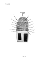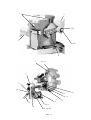
1
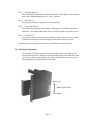
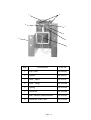
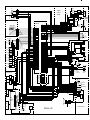
GODZILLA WARS Jnr.
Operators Manual
1. SPECIFICATIONS
POWER SUPPLY :-
220/240 Volts AC
CAPSULE SIZE :-
50mm DIAMETER
or
C2000 TICKET DISPENSER
DIMENSIONS :-
645(w) x 745(d) x 1665(h) (with header)
WEIGHT:-
77kg.
ACCESSORIES:-
Keys:
(Cash Door) .................................................... 2
(Coin Door) .................................................... 2
(Back Door) .................................................... 2
(Hopper Door) or (Dispenser Door) ............... 2
Operators Manual .............................................................. 1
Page 2
2. PRECAUTIONS
2-1 Cautions When Installing.
This game is designed for indoor use only. The game must not be installed outdoors or
under the following conditions:a.
In areas directly exposed to sunlight, high humidity, direct water contact, dust,
high heat or extreme cold.
b.
In locations that would present an obstacle in the case of an emergency, i.e. near
fire equipment or emergency exits.
c.
On an unstable surface or subject to floor vibration.
2-2 Caution When Handling.
a.
AC power must always be turned OFF, and the game disconnected, before
replacing any parts or connecting/disconnecting connectors.
b.
When unplugging the game from an electrical outlet, always grasp the plug, not the
mains lead.
c.
The machine must be earthed with a securely connected earthed plug.
d.
Care must be taken at all times to avoid electric shock when inspecting or
adjusting the game.
2-3 When Transporting.
a.
Do not subject the game to physical shock when transporting or moving it.
b.
Take care not to rope any plastic parts when transporting.
3. INSTALLATION
1.
Ensure that five ping-pong balls have been placed on the playfield, and the hopper
filled with capsules or the ticket dispenser loaded with tickets.
Page 3
4. HOW TO PLAY
1.
Insert coin/s to establish credit, shown on the credit display, then press the
dispense button once. Godzilla will begin to move and the background sounds will
begin.
2.
Pressing the bomb pushbutton when lit will fire a ping-pong ball at Godzilla. If the
timing is right the ball will go into Godzilla's mouth.
3.
If six balls are shot into Godzilla's mouth in the given time, Godzilla is defeated
and a prize or tickets will be dispensed.
4.
The game is over if the player fails to shoot six balls into Godzilla's mouth in the
given time.
5. ADJUSTMENTS
5-1. DIP Switch Settings
The DIP switches on the game PCB alter the price of play, game difficulty and ticket/
prize mode.
Note;- This machine is fitted with a credit dispense board, and the game PCB switches
should always be set for 1 coin 1 play and game pricing set using the credit
dispense board switches.
Always turn the machine OFF when adjusting DIP switches.
Function
Coin
1
2
3
1 coin - 1 play
ON
ON
ON
1 coin - 2 plays
off
on
on
1 coin - 3 plays
on
off
on
2 coins - 1 play
off
off
on
2 coins - 3 plays
on
on
off
3 coins - 1 play
off
on
off
3 coins - 2 plays
on
off
off
Free play
off
off
off
4
5
6
Hard
on
on
Medium
OFF
ON
Easy
on
off
Very Easy
off
off
7
8
2 tickets for each point
Number of
tickets
issued
ON
+10 tickets for 6 points
3 tickets for each point
off
+10 tickets for 6 points
Difficulty
Off = hopper mode / On= ticket mode
Sound in attract mode
OFF
Yes
ON
No
off
Page 4
Hopper Fuse (750ma)
Hopper Switch
Service switch
Volume Control
Test
Switch
1
2
3
4
5
Service LEDs
Coin Counter
Dispense Counter
Service Bracket
5-2. Volume Control
The volume control is fitted to the service bracket located inside the coin door.
5-3. Service Switch
Pressing the service switch establishes a game credit without operating the coin
counter.
5-4. Hopper Switch
If the hopper switch is pressed while the machine is in stand-by, the hopper will
turn and a capsule dispensed.
5-5. Test Switch
There are seven test steps. The steps are advanced each time the test switch is pressed.
Test 1 Mouth Motor Test
The mouth motor runs and count lamps 2 or 5 light when Optos 1 or 2 are
interrupted, and ping pong balls can be fired by pressing the bomb button.
Test 2 Godzilla Motor Test
Godzilla motor operates and count lamp 4 lights when Opto 3 is interrupted
Page 5
Test 3 Ball Shooting Test
The mouth opens and balls are automatically shot. The height to which balls are
shot can be adjusted during this test. (see 5-6 below)
Test 4 Sound Test
All the game sounds are produced one after another.
Test 5 Lamp and LED test
The count lamps light one after another. The game over and hit lamps flicker
alternately. The bomb button lamp and service LEDs light every other second.
Test 6 Switch Test
A bleep will sound each time the bomb button, hopper switch, service switch,
Godzilla's mouth microswitch or hopper outlet microswitch is pressed.
Pressing the test switch again will put the machine back to stand-by mode.
5-6. Ball Height Adjustment
The height to which the balls are fired can be adjusted by loosening (do not
remove) the two screws fixing the spring retaining plate on the side of the ball
shooter assy and moving the plate up or down. Ensure that the two screws are
fully tightened when adjustment is completed.
Ball Lower
Ball Height Adjust
Ball Higher
Page 6
6. TROUBLESHOOTING
The game constantly monitors certain functions and if there is a failure certain LEDs
or count lamps light as an indication.
The following table indicates these conditions.
Service LED Indication
Fault Indicated
Credit dispense pulse remains on
Service switch remains on
Mouth micro switch remains on
Hopper test switch remains on
Hopper microswitch remains on
Hopper not dispensed
Tickets run out
Ticket count switch remains on
Test switch remains on
Opto 3 remains on
Opto 2 remains on
Opto 1 remains on
Mouth motor not working
Count Lamp Indication
Fault Indicated
Mouth does not return to start position at
power-up
Godzilla does not return to start position
at power-up
Lamp OFF
Lamp ON
Page 7
7. PARTS
14,15 (behind
header)
8
13
9
1
10
4
2
7
11
3
5
6
17
12
16
Page 9
Item
Description
Part No
1
Building Vac-Form
88300850
2
Island Vac-Form
88300851
3
Field Guard Vac-Form
88300852
4
Rear Guard Acrylic
88300848
5
Play Panel
------------
6
Credit Display Panel
88300870
7
Side Acrylic L&R
88300846
8
Main Dome
88300845
9
Dome Stay LH
88300865
10
Dome Stay RH
88300866
11
Playfield Acrylic
88300847
12
Credit Display
81000112
13
Display Lamps 24v 3w Wedge Lamp
64000034
14
Speaker 4 1/2"
62000006
15
Speaker Grille
87800011
16
Credit Dispense Button
60200233
17
Bomb Button
60200257
Page 10
1
2
3, 22
5
4 (x2)
6
7
21, 23
1
17
16
9
10, 11
12
13
15
10, 11
14
18, 19, 20
Page 11
8
Item
Description
Part No
1
Opto Interrupter
88300893
2
Opto Interrupt Plate
88300901
3
Link Arm Stand-Off - Lower
88300896
4
Washer Link Arm Stand-Off
88300899
5
Mouth Motor 12v DC 40rpm
88300892
6
Crank Arm
88300900
7
Mouth Link Arm
88300894
8
Main Shaft & Mntg Assy
88300871
9
External Circlip 12mm
88300875
10
Delrin Bush
88300877
11
Nylon Washer
88300876
12
Retaining Clip
88300874
13
Main Motor 12v Step
88300885
14
Spring Bracket Upper
88300880
15
Step Motor Stabilising Spring
88300882
16
Spring Retainer
88300878
17
Spring Retainer Spacer
88300879
18
Roller Arm
88300885
19
Roller
88300886
20
Roller Bush
88300886
21
Link Arm Stand-Off - Upper
88300885
22
Spacing Bush - Lower
88300897
23
Spacing Bush - Upper
88300898
Page 12
2
1
8
3
4
7
5
6
Item
Description
Part No
1
Flip Arm
88300903
2
Spacer
88300917
3
Rod - Short
88300907
4
Rod - Long
88300906
5
Spring
88300909
6
Solenoid
88300908
7
Ball Shooter Main Bracket
88300902
8
Solenoid Link Plate
88300904
Page 13
POWER SUPPLY BOARD
8. SCHEMATIC - Power supply
Page 14
BOMB BUTTON
SCHAFFNER MAINS
ASSY
SW8
1
2
3
4
LP1
12V
SOL 3
1
2
3
4
F1
POWER
SUPPLY
BOARD
5A
GND 3
1 1
2 2
EARTH
21.5VAC
220VAC
PCB ASSY
SERVICE LED's
J2-40P
1
2
3
4
5
6
LED1
LED2
LED3
LED4
LED5
WHI/BRN
BLACK
BROWN
RED
YELLOW
ORANGE
1
2
3
4
5
6
GRN/WHI
GRY/WHI
BLUE
RED/GRN
BLU/WHI
RED/WHI
BLU/BLK
WHI/YEL
WHI/ORG
WHI/GRN
24V 0.15A
1
2
3
4
5
6
7
8
9
LP7
LP8
LP1
1
2
3
4
5
6
7
8
9
WHI/ORG
BLUE
PURPLE
YELLOW
RED/BLK
LP2
LP3
BROWN
WHITE
WHI/BRN
WHI/GRY
LP4
LP5
GRY
WHI/RED
WHI/PUR
PURPLE
YELLOW
BLACK
YELLOW
BLUE
LP6
LP9
A1
B1
A2
B2
A3
B3
A4
B4
A5
B5
A6
B6
A7
B7
A8
B8
A9
B9
A10
B10
A11
B11
A12
B12
A13
B13
A14
B14
A15
B15
A16
B16
A17
B17
A18
B18
A19
B19
A20
B20
+12V
LED 1
LED 2
LED 3
LED 4
LED 5
LED 6
LED 7
+24V
LP1
LP2
LP3
LP4
LP5
LP6
LP7
+12V
LP8
+24V
LP9
+12V
LP10
LP11
+12V
L/OUT-A
L/OUT-B
+12V
PAY-C
+12V
COIN-100
+12V
COIN-10
+24V
SOLENOID
HOP MOT
AGND
DCM+
DCMSPKR+
SPKR-
S10 MECHS ONLY
YELLOW
CC1
CC2
METER
C220
COIN
CREDIT
DISPENSE
BOARD
BLUE
WHITE
ORG/BLK
1
2
3
4
1 1
2 2
3 3
4 4
5 5
6 6
7 7
8 8
9 9
10 10
BLACK
1
2
3
4
1
2
3
4
5
6
7
8
9
1
2
3
4
5
6
7
8
9
S
1
2
3
4
5
6
ORANGE
BLACK
YELLOW
BLACK
RED
BLACK
COM_A
STMA
STMA
COM_B
STMB
STMB
P
1
2
3
4
5
6
S
1
2
3
4
5
6
YELLOW
BLACK
GREEN
WHITE
RED
BLACK
1
2
3
4
5
6
1
2
3
4
5
6
DC24V
BGND
DC12V
AGND
DC7V
GND
1
2
3
4
5
6
7
8
9
GND 3
11.6VAC
1
2
3
4
5
6
7
8
9
240VAC
7.4VAC
OVAC
GND 1
GND 2
GND 3
1
2
3
4
5
6
1
2
3
4
5
6
M1
M
24V
STEPPER
MOTOR
J1-30P
+5V
A1 A1
+5V
B1 B1
+5V
A2 A2
+5V
B2 B2
CHAR SW
A3 A3
GND
B3 B3
CLOSE SW
A4 A4
OPEN SW
B4 B4
GND
A5 A5
PHOTO SW1 B5 B5
GND
A6 A6
GND
B6 B6
B SHOT SW A7 A7
AGND
B7 B7
B SHOC SW A8 A8
AGND
B8 B8
COIN 1 SW A9 A9
COIN 2 SW B9 B9
AGND
A10 A10
TEST SW
B10 B10
PAY SW
A11 A11
SERV SW
B11 B11
AGND
A12 A12
HOPP SW
B12 B12
AGND
A13 A13
SW1 SPARE B13 B13
SW2 SPARE A14 A14
SW3 SPAREB14 B14
AGND
A15 A15
AGND
A15 A15
BLACK
LP10
A1
B1
A2
B2
A3
B3
A4
B4
A5
B5
A6
B6
A7
B7
A8
B8
A9
B9
A10
B10
A11
B11
A12
B12
A13
B13
A14
B14
A15
B15
A16
B16
A17
B17
A18
B18
A19
B19
A20
B20
+24V
BGND
+12V
AGND
+7V
GND
P
1
2
3
4
5
6
AC3
AC4
EARTH
AC24V1
AC24V2
AC12V1
AC12V2
AC9V1
AC9V2
220-240V
MAINS
IN
1
2
3
4
5
6
7
WHITE
RED
BROWN
ORANGE
BLU/RED
1 1
2 2
3 3
4 4
5 5
6 6
7 7
8 8
9 9
10 10
11 11
12 12
BLU/WHI
BLU/YEL
PINK
PURPLE
WHI/BLK
WHI/GREY
WHI/PUR
WHI/BRN
WHI/RED
WHI/ORG
WHI/GRN
WHI/YEL
WHI/BLU
PHOTO 3
+5V
SIG
GND
PHOTO 1
+5V
SIG
GND
PHOTO 2
SW7
1 1
2 2
M2
M
MOUTH MOTOR
LP12
12V 6W
MOUTH
SW6
1
2
3
4
5
6
7
8
9
1
2
3
4
5
6
7
8
9
HOPPER SW
M3
M
METER VMOTOR V+
GROUND
+12V
METER V+
+12V
+12V
METER VMETER V+
MOTOR V+
AGND
AGND
TICKET
DISPENSER
CONNECTIONS
F1
GND 2
+5V
SIG
GND
1 1
2 2
3 3
4 4
5 5
6 6
7 7
8 8
9 9
10 10
11 11
12 12
HOPPER
ASSY
0.8A
SW5 TEST
SW4 PAY
SW3 SERVICE
VOLUME
CONTROL
DISPENSE
COUNTER
+
GND 1
1 1
2 2
3 3
DISPENSE SW
MECH
CREDIT
DISPLAY
DISPENSE LAMP
SERVICE BRACKET
GODZILLA JNR