1
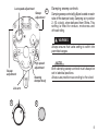
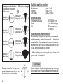
Owners Manual
MX & Enduro steering dampers SD 415, 425
Including:
Safety
Design
features
Basic
adjustments
Technical
information
1
Safety signals
Important information concerning safety is
distinguished in this manual by the following
notations:
The Safety alert symbol means:
Caution! Your safety is involved.
Introduction
Öhlins steering dampers are designed to
withstand very tough treatment in conjunction
with competitions. Many years experience and
close cooperation with World Championship
teams in motocross and enduro has helped us
develop unique know-how.
Before installation
WARNING!
Failure to follow warning instructions could result
in severe or fatal injury to anyone working with,
inspecting or using the suspension, or to
bystanders.
Öhlins Racing AB can not be held responsible for
any damage whatsoever to shock absorber or
vehicle, or injury to persons, if the instructions
for fitting and maintenance are not followed
exactly.
Similarly, the warranty will become null and void
if the instructions are not adhered to.
CAUTION!
Caution indicates that special precautions
must be taken to avoid damage to the
suspension.
NOTE!
This indicates information that is of importance
with regard to procedures.
2
© Öhlins Racing AB.
All rights reserved.
Any reprinting or unauthorized use
without the written permission of
Öhlins Racing AB is prohibited.
Printed in Sweden.
WARNING!
1. Installing a steering damper, that is not
approved by the vehicle manufacturer, may affect
the stability of your vehicle. Öhlins Racing AB
cannot be held responsible for any personal injury
or damage whatsoever that may occur after
fitting the steering damper. Contact an Öhlins
dealer or other qualified person for advice.
2. Please study and make certain that you fully
understand all the mounting instructions and the
owners manuals before handling this steering
damper kit. If you have any questions regarding
proper installation procedures, contact an Öhlins
dealer or other qualified person.
3. The vehicle service manual must be referred
to when installing the Öhlins steering damper.
CAUTION!
Make sure that the steering stops work properly.
If not, it´s necessary to adjust the steering stops
(use washer or suchlike). If the damper is used
as stop it can be damaged.
Öhlins products are subject to continual
improvement and development. Consequently, although these instructions include the most up-todate information available at the time of printing,
there may be minor differences between your suspension and this manual. Please consult your
Öhlins dealer if you have any questions with regard
to the contents of the manual.
NOTE!
During storage and transportation, especially at
high ambient temperature, the oil and grease
used for assembling may run out inside the
packing and damage the expanded polystyrene
packing material. This is not unusual and is in no
way detrimental to the steering damper.
NOTE!
Please note that all bikes require bars with a minimum of 40 mm between crossbar and main bar for
damper to fit. For applications with less than this
clearance use: PROTAPERS, Scotts Renthals or
special handlebars with no crossbar. You´re going
to pre-assemble everything before permanently
mounting or drilling anything. This will insure proper
alignment and fit, otherwise you may find some hidden problems you didn´t anticipate.
3
Design
Setting
The Öhlins steering damper is a hydraulic
damper that counteracts wobble, alleviates
shock against the front wheel and prevents head
shake/cast by the motorcycle, which gives safer
riding.
The damper is fitted on the upper fork crown,
in the centre over the steering stem (fig.1). When
turning, and in the event of wobbling, shock, etc,
the link arm of the damper is twisted, thus forcing
fluid through three independently acting valve
systems in the damper cover.
The steering damper has three external setting
possibilites, ie, setting of the damper valve, highspeed valve and sweep valve, which regulate
the damping area (fig.2).
1
Low speed valve
Öhlins steering damper is delivered with the low
speed valve set in a basic position that gives maximum basic damping. For enduro and motocross
it is suitable to set the low speed in position 4-8,
depending on the track and the rider.
Turn clockwise to increase damping and
counter clockwise to reduce it (fig.3).
High speed valve
The high-speed valve (fig.4) is set between 11/4
to 2 turns from the bottom position, suitable
for enduro, motocross and off-road.
WARNING!
For all riding purposes the high-speed valve must
be loosened at least 1 turn from the bottom.
Otherwise the damping forces will become too
high, making the ride hazardous.
4
Low speed adjustment
Sweep
adjustment
2
Damping sweep controls
Damping sweep controls (fig.8) are located on each
side off the damper body. Damping is in position
2, (12 o´clock), when delivered from Öhlins. This
setting is fitted for enduro, motocross and
off-road riding.
WARNING
Always ensure that valve setting is within the
permitted ranges.
Sweep
adjustment
High speed
adjustment
Steering
damper body
NOTE!
Both damping sweep controls must always be
set in identical positions.
Always use positions according to the clock.
Link arm
3
4
5
Sweep control valve
Located on the side
of the unit
Damping range
5
Suitable starting position:
Motocross
Enduro
Off-Road
pos.1 or 2
pos.2 or 3
pos.2, 3 or 4
Position 1
9 o´clock
Position 1
Damping 34°
Position 2
12 o´clock
Position 2
Damping 44°
Position 3
3 o´clock
Position 3
Damping 54°
The steering damper is a precision instrument,
with extremely fine tolerances. It is therefore
essential that it is maintained in a correct manner.
Maintenance and service should be carried out
by an authorised service center.
Position 4
6 o´clock
Position 4
Damping 90°
- After washing the motorcycle wipe clean and
spray with all-round oil.
Technical data
External measures
Seals
Oil
Maintenance and inspection
12
Sweep controls located on
each side are normally set at
the twelve o´clock position.
9
3
6
6
70x70x35 mm
Low friction type
Öhlins part no.
01306-01
CAUTION!
Never subject to direct high-pressure cleaning
since water may otherwise penetrate the damper.
CAUTION!
Ensure that there is no leakage of fluid and that
there is no visible damage to the housing and
mounts.
Change the fluid regularly. In new dampers after
10 hours riding and then every 20 hours riding.
Use only recommended fluid that is tested and
approved by us. We cannot guarantee fully
acceptable operation using other fluids.
NOTE!
Regular maintenance and inspection counteracts
possible malfunction.
If the steering damper needs service, Öhlins
agents have the proper tools and know-how to
solve all technical problems.
NOTE!
Discarded Öhlins products should be handled
over to an authorized work shop or distributor
for proper disposal.
Trouble Shooting
Little or no damping
1
Debris in valving or worn parts internally, need
service.
2
Shear pin on bottom has broken due to a crash
or over stressing. This can be replaced easily by
removing the link-arm with a link-arm puller
(4954-01) and installing a new shear pin.
Dampens more to one side
than the other
1
It´s new, give it a little time to seat the valving.
2
The oil is dirty and it need servicing.
Knob has come off
1
Don´t panic, it will still work. To repair it, remove
the set screw, put the knob back on and allow it
to seat over the o-ring. Reinsert the steel ball,
then the spring and finally the set screw until
flush with the top of the knob.
7
Weld-on tower for
Öhlins Off Road steering dampers
3
Install the damper to the new handlebar mount.
Use the two Allen bolts provided.
NOTE!
If the damper does not fit between the main bar
and the crossbar, bow or bend the crossbar slightly
to allow clearance. Minimum 40 mm is required.
4
With the damper fitted and the handlebar bolts
evenly seated, hold the weld-on tower temporarily
in position. Mark where it must be cut for perfect fit
between the frame and the link-arm of the damper.
Mounting Instruction
1
Remove the original upper handlebar mounting
clamps and the fuel tank of the motorcycle.
2
Install the one-piece upper handlebar mount provided.
Tighten the bolts evenly to allow fine adjustment later.
Keep the gap equal as shown in figure. According to
the handle bar clamp mounting instruction.
8
NOTE!
The ”tower pin” is not to be installed into the
tower yet.
5
The weld-on tower can be
cut at either end for proper
lenght. Cutting at the top is
usually the easiest way
Sometimes grinding at the
base of the tower to match
the frame is required.
Cut here for
proper lenght
CAUTION!
When installed the tower pin must reach 0.5 mm
above the upper surface of the link-arm.This is specially important when handlebar has rubber
mounted lower mounts, where handlebar is allowed to flex downvards. If the link-arm touches
the frame bracket the damper can be damaged.
CAUTION!
The weld-on tower is made of steel and can be
welded with standard weldning rod. This should be
carried out by qualified personnel. Tig weldning is
prefered.. Gas welding requires carefull protection
of the bearings and seals of the triple clamps.
0,5 mm
Weld
6
With tower cut to correct height, deburr the hole
in top before installing the tower pin. Grease the
pin slightly before installation.
7
Weld the tower to the frame (tig welding recommended). Make welds om both sides of the
tower. (A tower of correct height will need no
additional holding devices to the frame)
CAUTION!
To gain a strong weld it is of importance to carefully remove paint and debris.
WARNING!
Certain modifications can be necessary to install the
weld-on tower. It is vital that the mounting instructions are carefully followed.
9
Handlebar clamp for
Öhlins Off Road steering damper
Handlebar clamp
Alignment
Steering
clamper
Mounting instructions
1
Handlebar
clamp
Replace the stock handlebar upper brackets
mount with the handlebar clamp provided.
CAUTION!
It is vital that the centre of the steering damper
mounting bolts are aligned with the centre of the
steering stem
2
When the lower handlebar brackets are
reversible, the brackets must be positioned
according to the above mentioned caution.
10
Weld
on tower
Motorcycle
steering column
Steering damper
1
Attach the steering damper with the bolts
enclosed.
NOTE!
The steering damper link arm should be at least
0.5 mm below the upper edge of the lower pin.
0.5 mm
Link arm
2
It is possible to make smaller adjustments with the
four bolts holding the handlebar clamps. If the front
bolts are tightened and the rear bolts are slackened
the distance is decreased and vice versa.
NOTE!
Ensure that the pin is in the middle of the link
arm groove (see illustration).
CAUTION!
Make certain that the steering stops are working
properly. If the damper acts as a stopper it can
be damaged.
min 1 mm
min 1 mm
NOTE!
Make sure that all bolts are tightened to the correct torgue and that nothing fouls or restricts the
handlebar when beeing turned to each side. When
testing, the damper adjuster must be in soft damping position)
11
More info
The ultimate suspension site.
Find out everything about your suspension.
Download mounting instructions, manuals and
brochures. And a lot more.
Öhlins Racing AB
Box 722, SE-194 27 Upplands Väsby, Sweden
Phone +46 8 590 025 00, fax +46 8 590 025 80
12
07270-04, Teknisk Illustration,OM MX & Enduro SD 415, 425. 05 04.
www.ohlins.com