1
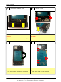
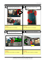
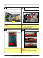
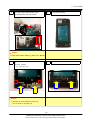
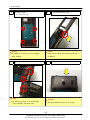
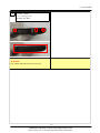
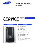
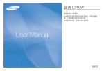
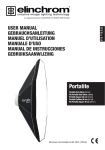
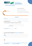
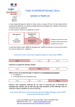
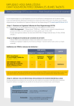
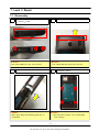
7. Level 2 Repair
7-1. Disassembly
1
2
1) Detach Top Deco.
1) Disassemble the Top Cover.
2) Unscrew 3 Points.
( Caution
( Caution
1) Be careful USB Port Cover not to be lost
3
1) Be careful USB Port Cover not to be lost
4
1) Disassemble the Body Case.
1) Unscrew 4 points.
( Caution
( Caution
1) Be careful RF connector not to be damaged
1) Slide up the Body Case following guide line on
the Bracket
when screwing.
7-1
SAMSUNG Proprietary-Contents may change without notice
This Document can not be used without Samsung's authorization
7. Level 2 Repair
5
6
1) Disassemble the Bottom Cover
( Caution
1) Unscrew 2 points.
2) Disassemble the Antenna module.
( Caution
1) Be careful Antenna module not to be damaged.
1) Be careful Antenna module not to be damaged.
7
8
1) Disassemble the Rear
( Caution
1) Unscrew 4 points.
( Caution
1) Be careful FPCB not to be Damaged
1) Be careful Antenna module not to be damaged.
7-2
SAMSUNG Proprietary-Contents may change without notice
This Document can not be used without Samsung's authorization
7. Level 2 Repair
9
10
1) Disassemble SPK module from PBA
1) Detach the Volume, CAM Key FPCB
2) Detach Receiver, SUB Key FPCB
2) Disconnect SPK module FPCB from PBA.
Connector.
( Caution
( Caution
1) Be careful FPCB not to be damaged.
11
1) Disconnect OCTA FPCB connector.
2) Separate PBA with FRONT Ass'y.
1) Be careful FPCB not to be damaged.
12
1) Disassemble the OCTA with Bracket
( Caution
( Caution
1) Be careful OCTA & FPCB not to damaged.
1) Be careful OCTA & FPCB not to damaged.
7-3
SAMSUNG Proprietary-Contents may change without notice
This Document can not be used without Samsung's authorization
7. Level 2 Repair
7-2. Assembly
1
1) Insert OCTA FPCB to the hole in the Bracket.
2) Assemble the OCTA with the Bracket.
2
2) Assemble PBA and FRONT Ass'y.
( Caution
( Caution
1) Be careful Receiver FPCB not to be got in
1) Be careful OCTA & FPCB not to be damaged.
3
1) Connect OCTA FPCB to PBA.
between PBA and Bracket.
4
1) Connect Receiver, SUB Key FPCB
Connector.
1) Attach the Volume, CAM Key FPCB on the
Bracket.
( Caution
1) Check FPCB holding by guide on the Bracket.
7-4
SAMSUNG Proprietary-Contents may change without notice
This Document can not be used without Samsung's authorization
7. Level 2 Repair
5
1) Connect SPK module FPCB to PBA.
6
1) Assemble the Rear.
8
1)Assemble the Bottom Cover.
2) Assemble PBA and SPK module.
( Caution
1) Check SPK module holding by guide on the Bracket.
7
1) Assemble Antenna module
2) Screw 2 points.
- 1.2 ± 0.1 kgf / cm
( Caution
1) Assemble & Screw Antenna module only.
Do not Screw on the Rear yet.
7-5
SAMSUNG Proprietary-Contents may change without notice
This Document can not be used without Samsung's authorization
7. Level 2 Repair
5
6
1) Screw 4 points.
1) Assemble the Body Case.
- 1.2 ± 0.1 kgf / cm
( Caution
( Caution
1) Be careful RF connector not to be damaged
1) Slide down the Body Case following guide line on
the Bracket
when screwing.
7
8
1) assemble the Case Body.
( Caution
1) Be careful Key FPCB not to be damaged.
when assembling with Body Case.
1) Assemble the Top Cover.
( Caution
1) Be careful USB Port Cover not to be lost
7-6
SAMSUNG Proprietary-Contents may change without notice
This Document can not be used without Samsung's authorization
7. Level 2 Repair
9
1) screw 3 points.
- 1.2 ± 0.1 kgf / cm
2) Attach Top Deco.
( Caution
1) Be careful USB Port Cover not to be lost
7-7
SAMSUNG Proprietary-Contents may change without notice
This Document can not be used without Samsung's authorization