1
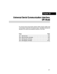
Chapter 21
Universal Serial Communication Interface,
I2C Mode
The universal serial communication interface (USCI) supports multiple serial
communication modes with one hardware module. This chapter discusses the
operation of the I2C mode.
Topic
Page
21.1 USCI Overview . . . . . . . . . . . . . . . . . . . . . . . . . . . . . . . . . . . . . . . . . . . . . . . 21-2
21.2 USCI Introduction: I2C Mode . . . . . . . . . . . . . . . . . . . . . . . . . . . . . . . . . . 21-3
21.3 USCI Operation: I2C Mode . . . . . . . . . . . . . . . . . . . . . . . . . . . . . . . . . . . . 21-5
21.4 USCI Registers: I2C Mode . . . . . . . . . . . . . . . . . . . . . . . . . . . . . . . . . . . . 21-25
Universal Serial Communication Interface, I2C Mode
21-1
USCI Overview
21.1 USCI Overview
The universal serial communication interface (USCI) modules support
multiple serial communication modes. Different USCI modules support
different modes. Each different USCI module is named with a different letter.
For example, USCI_A is different from USCI_B, etc. If more than one identical
USCI module is implemented on one device, those modules are named with
incrementing numbers. For example, if one device has two USCI_A modules,
they are named USCI_A0 and USCI_A1. See the device-specific data sheet
to determine which USCI modules, if any, are implemented on which devices.
The USCI_Ax modules support:
-
UART mode
Pulse shaping for IrDA communications
Automatic baud rate detection for LIN communications
SPI mode
The USCI_Bx modules support:
- I2C mode
- SPI mode
21-2
Universal Serial Communication Interface, I2C Mode
USCI Introduction: I2C Mode
21.2 USCI Introduction: I2C Mode
In I2C mode, the USCI module provides an interface between the MSP430 and
I2C-compatible devices connected by way of the two-wire I2C serial bus.
External components attached to the I2C bus serially transmit and/or receive
serial data to/from the USCI module through the 2-wire I2C interface.
The I2C mode features include:
- Compliance to the Philips Semiconductor I2C specification v2.1
J 7-bit and 10-bit device addressing modes
J General call
J START/RESTART/STOP
J Multi-master transmitter/receiver mode
J Slave receiver/transmitter mode
J Standard mode up to 100 kbps and fast mode up to 400 kbps support
- Programmable UCxCLK frequency in master mode
- Designed for low power
- Slave receiver START detection for auto-wake up from LPMx modes
- Slave operation in LPM4
Figure 21−1 shows the USCI when configured in I2C mode.
Universal Serial Communication Interface, I2C Mode
21-3
USCI Introduction: I2C Mode
Figure 21−1. USCI Block Diagram: I 2C Mode
UCA10 UCGCEN
Own Address UC1OA
UCxSDA
Receive Shift Register
Receive Buffer UC1RXBUF
I2C State Machine
Transmit Buffer UC1TXBUF
Transmit Shift Register
Slave Address UC1SA
UCSLA10
UCxSCL
UCSSELx
Bit Clock Generator
UCxBRx
UC1CLK
00
ACLK
01
SMCLK
10
SMCLK
11
21-4
16
UCMST
BRCLK
Prescaler/Divider
Universal Serial Communication Interface, I2C Mode
USCI Operation: I2C Mode
21.3 USCI Operation: I2C Mode
The I2C mode supports any slave or master I2C-compatible device.
Figure 21−2 shows an example of an I2C bus. Each I2C device is recognized
by a unique address and can operate as either a transmitter or a receiver. A
device connected to the I2C bus can be considered as the master or the slave
when performing data transfers. A master initiates a data transfer and
generates the clock signal SCL. Any device addressed by a master is
considered a slave.
I2C data is communicated using the serial data pin (SDA) and the serial clock
pin (SCL). Both SDA and SCL are bidirectional, and must be connected to a
positive supply voltage using a pullup resistor.
Figure 21−2. I 2C Bus Connection Diagram
VCC
Device A
MSP430
Serial Data (SDA)
Serial Clock (SCL)
Device B
Device C
Note: SDA and SCL Levels
The MSP430 SDA and SCL pins must not be pulled up above the MSP430
VCC level.
Universal Serial Communication Interface, I2C Mode
21-5
USCI Operation: I2C Mode
21.3.1 USCI Initialization and Reset
The USCI is reset by a PUC or by setting the UCSWRST bit. After a PUC, the
UCSWRST bit is automatically set, keeping the USCI in a reset condition. To
select I2C operation the UCMODEx bits must be set to 11. After module
initialization, it is ready for transmit or receive operation. Clearing UCSWRST
releases the USCI for operation.
Configuring and reconfiguring the USCI module should be done when
UCSWRST is set to avoid unpredictable behavior. Setting UCSWRST in I2C
mode has the following effects:
-
I2C communication stops
SDA and SCL are high impedance
UCBxI2CSTAT, bits 6-0 are cleared
UCBxTXIE and UCBxRXIE are cleared
UCBxTXIFG and UCBxRXIFG are cleared
All other bits and registers remain unchanged.
Note: Initializing or Reconfiguring the USCI Module
The recommended USCI initialization/re-configuration process is:
1) Set UCSWRST (BIS.B #UCSWRST,&UCxCTL1)
2) Initialize all USCI registers with UCSWRST=1 (including UCxCTL1)
3) Configure ports.
4) Clear UCSWRST via software (BIC.B
#UCSWRST,&UCxCTL1)
5) Enable interrupts (optional) via UCxRXIE and/or UCxTXIE
21-6
Universal Serial Communication Interface, I2C Mode
USCI Operation: I2C Mode
21.3.2 I2C Serial Data
One clock pulse is generated by the master device for each data bit
transferred. The I2C mode operates with byte data. Data is transferred most
significant bit first as shown in Figure 21−3.
The first byte after a START condition consists of a 7-bit slave address and the
R/W bit. When R/W = 0, the master transmits data to a slave. When R/W = 1,
the master receives data from a slave. The ACK bit is sent from the receiver
after each byte on the 9th SCL clock.
Figure 21−3. I 2C Module Data Transfer
SDA
MSB
Acknowledgement
Signal From Receiver
Acknowledgement
Signal From Receiver
SCL
1
START
Condition (S)
2
7
8
R/W
9
ACK
1
2
8
9
ACK
STOP
Condition (P)
START and STOP conditions are generated by the master and are shown in
Figure 21−3. A START condition is a high-to-low transition on the SDA line
while SCL is high. A STOP condition is a low-to-high transition on the SDA line
while SCL is high. The bus busy bit, UCBBUSY, is set after a START and
cleared after a STOP.
Data on SDA must be stable during the high period of SCL as shown in
Figure 21−4. The high and low state of SDA can only change when SCL is low,
otherwise START or STOP conditions will be generated.
Figure 21−4. Bit Transfer on the I 2C Bus
Data Line
Stable Data
SDA
SCL
Change of Data Allowed
Universal Serial Communication Interface, I2C Mode
21-7
USCI Operation: I2C Mode
21.3.3 I2C Addressing Modes
The I2C mode supports 7-bit and 10-bit addressing modes.
7-Bit Addressing
In the 7-bit addressing format, shown in Figure 21−5, the first byte is the 7-bit
slave address and the R/W bit. The ACK bit is sent from the receiver after each
byte.
Figure 21−5. I 2C Module 7-Bit Addressing Format
1
1
1
R/W
ACK
7
S
Slave Address
1
8
Data
1
8
ACK
Data
1
ACK P
10-Bit Addressing
In the 10-bit addressing format, shown in Figure 21−6, the first byte is made
up of 11110b plus the two MSBs of the 10-bit slave address and the R/W bit.
The ACK bit is sent from the receiver after each byte. The next byte is the
remaining 8 bits of the 10-bit slave address, followed by the ACK bit and the
8-bit data.
Figure 21−6. I 2C Module 10-Bit Addressing Format
1
1
7
S Slave Address 1st byte
1
1
1
1
0
X
R/W
1
1
8
1
8
ACK Slave Address 2nd byte ACK
Data
1
ACK P
X
Repeated Start Conditions
The direction of data flow on SDA can be changed by the master, without first
stopping a transfer, by issuing a repeated START condition. This is called a
RESTART. After a RESTART is issued, the slave address is again sent out with
the new data direction specified by the R/W bit. The RESTART condition is
shown in Figure 21−7.
Figure 21−7. I 2C Module Addressing Format with Repeated START Condition
1
7
1
S
Slave Address
1
21-8
1
R/W ACK
8
1
1
Data
ACK
S
1
7
Slave Address
Any
Number
Universal Serial Communication Interface, I2C Mode
1
1
R/W ACK
8
1
1
Data
ACK
P
Any Number
USCI Operation: I2C Mode
21.3.4 I2C Module Operating Modes
In I2C mode the USCI module can operate in master transmitter, master
receiver, slave transmitter, or slave receiver mode. The modes are discussed
in the following sections. Time lines are used to illustrate the modes.
Figure 21−8 shows how to interpret the time line figures. Data transmitted by
the master is represented by grey rectangles, data transmitted by the slave by
white rectangles. Data transmitted by the USCI module, either as master or
slave, is shown by rectangles that are taller than the others.
Actions taken by the USCI module are shown in grey rectangles with an arrow
indicating where in the the data stream the action occurs. Actions that must
be handled with software are indicated with white rectangles with an arrow
pointing to where in the data stream the action must take place.
Figure 21−8. I 2C Time line Legend
Other Master
Other Slave
USCI Master
USCI Slave
...
Bits set or reset by software
...
Bits set or reset by hardware
Universal Serial Communication Interface, I2C Mode
21-9
USCI Operation: I2C Mode
Slave Mode
The USCI module is configured as an I2C slave by selecting the I2C mode with
UCMODEx = 11 and UCSYNC = 1 and clearing the UCMST bit.
Initially the USCI module must be configured in receiver mode by clearing the
UCTR bit to receive the I2C address. Afterwards, transmit and receive
operations are controlled automatically depending on the R/W bit received
together with the slave address.
The USCI slave address is programmed with the UCBxI2COA register. When
UCA10 = 0, 7-bit addressing is selected. When UCA10 = 1, 10-bit addressing
is selected. The UCGCEN bit selects if the slave responds to a general call.
When a START condition is detected on the bus, the USCI module will receive
the transmitted address and compare it against its own address stored in
UCBxI2COA. The UCSTTIFG flag is set when address received matches the
USCI slave address.
I 2C Slave Transmitter Mode
Slave transmitter mode is entered when the slave address transmitted by the
master is identical to its own address with a set R/W bit. The slave transmitter
shifts the serial data out on SDA with the clock pulses that are generated by
the master device. The slave device does not generate the clock, but it will hold
SCL low while intervention of the CPU is required after a byte has been
transmitted.
If the master requests data from the slave the USCI module is automatically
configured as a transmitter and UCTR and UCBxTXIFG become set. The SCL
line is held low until the first data to be sent is written into the transmit buffer
UCBxTXBUF. Then the address is acknowledged, the UCSTTIFG flag is
cleared, and the data is transmitted. As soon as the data is transferred into the
shift register the UCBxTXIFG is set again. After the data is acknowledged by
the master the next data byte written into UCBxTXBUF is transmitted or if the
buffer is empty the bus is stalled during the acknowledge cycle by holding SCL
low until new data is written into UCBxTXBUF. If the master sends a NACK
succeeded by a STOP condition the UCSTPIFG flag is set. If the NACK is
succeeded by a repeated START condition the USCI I2C state machine
returns to its address-reception state.
Figure 21−9 illustrates the slave transmitter operation.
21-10
Universal Serial Communication Interface, I2C Mode
USCI Operation: I2C Mode
Figure 21−9. I 2C Slave Transmitter Mode
Reception of own
S
SLA/R
address and
transmission of data
bytes
UCTR= 1(Transmitter)
UCSTTIFG= 1
UCBxTXIFG= 1
UCSTPIFG=?0
UCBxTXBUF discarded
A
DATA
A
DATA
Write data to UCBxTXBUF
UCBxTXIFG= 1
A
DATA
A
P
UCBxTXIFG= 0
UCSTPIFG= 1
UCSTTIFG= 0
Bus stalled (SCL held low)
until data available
Write data to UCBxTXBUF
Repeated start −
continue as
slave transmitter
DATA
A
S
SLA/R
UCBxTXIFG=0
UCTR= 1(Transmitter)
UCSTTIFG= 1
UCBxTXIFG= 1
UCBxTXBUF discarded
Repeated start −
continue as
slave receiver
DATA
A
S
SLA/W
UCBxTXIFG= 0
Arbitration lost as
master and
addressed as slave
UCTR= 0(Receiver)
UCSTTIFG= 1
A
UCALIFG= 1
UCMST= 0
UCTR= 1(Transmitter)
UCSTTIFG= 1
UCBxTXIFG= 1
UCSTPIFG= 0
Universal Serial Communication Interface, I2C Mode
21-11
USCI Operation: I2C Mode
I 2C Slave Receiver Mode
Slave receiver mode is entered when the slave address transmitted by the
master is identical to its own address and a cleared R/W bit is received. In slave
receiver mode, serial data bits received on SDA are shifted in with the clock
pulses that are generated by the master device. The slave device does not
generate the clock, but it can hold SCL low if intervention of the CPU is required
after a byte has been received.
If the slave should receive data from the master the USCI module is
automatically configured as a receiver and UCTR is cleared. After the first data
byte is received the receive interrupt flag UCBxRXIFG is set. The USCI
module automatically acknowledges the received data and can receive the
next data byte.
If the previous data was not read from the receive buffer UCBxRXBUF at the
end of a reception, the bus is stalled by holding SCL low. As soon as
UCBxRXBUF is read the new data is transferred into UCBxRXBUF, an
acknowledge is sent to the master, and the next data can be received.
Setting the UCTXNACK bit causes a NACK to be transmitted to the master
during the next acknowledgment cycle. A NACK is sent even if UCBxRXBUF
is not ready to receive the latest data. If the UCTXNACK bit is set while SCL
is held low the bus will be released, a NACK is transmitted immediately, and
UCBxRXBUF is loaded with the last received data. Since the previous data
was not read that data will be lost. To avoid loss of data the UCBxRXBUF
needs to be read before UCTXNACK is set.
When the master generates a STOP condition the UCSTPIFG flag is set.
If the master generates a repeated START condition the USCI I2C state
machine returns to its address reception state.
Figure 21−10 illustrates the the I2C slave receiver operation.
21-12
Universal Serial Communication Interface, I2C Mode
USCI Operation: I2C Mode
Figure 21−10. I 2C Slave Receiver Mode
Reception of own
address and data
bytes. All are
acknowledged.
S
SLA/W
A
DATA
A
DATA
A
DATA
A
P or S
UCBxRXIFG= 1
UCTR= 0(Receiver)
UCSTTIFG= 1
UCSTPIFG= 0
Bus stalled
(SCL held low)
if UCBxRXBUF not read
Refer to:
Slave Transmitter
Timing Diagram
Read data from UCBxRXBUF
Last byte is not
acknowledged.
DATA
UCTXNACK= 1
A
P or S
UCTXNACK= 0
Bus not stalled even if
UCBxRXBUF not read
Reception of the
general call
address.
Gen Call
A
UCTR= 0(Receiver)
UCSTTIFG= 1
UCGC= 1
Arbitration lost as
master and
addressed as slave
A
UCALIFG= 1
UCMST= 0
UCTR= 0 (Receiver)
UCSTTIFG= 1
(UCGC= 1if general call)
UCBxTXIFG= 0
UCSTPIFG= 0
Universal Serial Communication Interface, I2C Mode
21-13
USCI Operation: I2C Mode
I 2C Slave 10-Bit Addressing Mode
The 10-bit addressing mode is selected when UCA10 = 1 and is as shown in
Figure 21−11. In 10-bit addressing mode, the slave is in receive mode after the
full address is received. The USCI module indicates this by setting the
UCSTTIFG flag while the UCTR bit is cleared. To switch the slave into
transmitter mode the master sends a repeated START condition together with
the first byte of the address but with the R/W bit set. This will set the UCSTTIFG
flag if it was previously cleared by software and the USCI modules switches
to transmitter mode with UCTR = 1.
Figure 21−11.I 2C Slave 10-bit Addressing Mode
Slave Receiver
Reception of own
address and data
bytes. All are
acknowledged.
S
11110 xx/W
A
SLA (2.)
DATA
A
DATA
A
A
P or S
UCBxRXIFG= 1
UCTR= 0( Receiver)
UCSTTIFG= 1
UCSTPIFG= 0
Reception of the
general call
address.
Gen Call
A
DATA
DATA
A
A
P or S
UCBxRXIFG= 1
UCTR= 0(Receiver)
UCSTTIFG= 1
UCGC= 1
Slave Transmitter
Reception of own
address and
transmission of data
bytes
S
11110 xx/W
A
SLA (2.)
A
S
11110 xx/R
DATA
UCSTTIFG= 0
UCTR= 0(Receiver)
UCSTTIFG= 1
UCSTPIFG= 0
UCTR= 1(Transmitter)
UCSTTIFG= 1
UCBxTXIFG= 1
UCSTPIFG= 0
21-14
A
Universal Serial Communication Interface, I2C Mode
A
P or S
USCI Operation: I2C Mode
Master Mode
The USCI module is configured as an I2C master by selecting the I2C mode
with UCMODEx = 11 and UCSYNC = 1 and setting the UCMST bit. When the
master is part of a multi-master system, UCMM must be set and its own
address must be programmed into the UCBxI2COA register. When
UCA10 = 0, 7-bit addressing is selected. When UCA10 = 1, 10-bit addressing
is selected. The UCGCEN bit selects if the USCI module responds to a general
call.
I 2C Master Transmitter Mode
After initialization, master transmitter mode is initiated by writing the desired
slave address to the UCBxI2CSA register, selecting the size of the slave
address with the UCSLA10 bit, setting UCTR for transmitter mode, and setting
UCTXSTT to generate a START condition.
The USCI module checks if the bus is available, generates the START
condition, and transmits the slave address. The UCBxTXIFG bit is set when
the START condition is generated and the first data to be transmitted can be
written into UCBxTXBUF. As soon as the slave acknowledges the address the
UCTXSTT bit is cleared.
The data written into UCBxTXBUF is transmitted if arbitration is not lost during
transmission of the slave address. UCBxTXIFG is set again as soon as the
data is transferred from the buffer into the shift register. If there is no data
loaded to UCBxTXBUF before the acknowledge cycle, the bus is held during
the acknowledge cycle with SCL low until data is written into UCBxTXBUF.
Data is transmitted or the bus is held as long as the UCTXSTP bit or UCTXSTT
bit is not set.
Setting UCTXSTP will generate a STOP condition after the next acknowledge
from the slave. If UCTXSTP is set during the transmission of the slave’s
address or while the USCI module waits for data to be written into
UCBxTXBUF, a STOP condition is generated even if no data was transmitted
to the slave. When transmitting a single byte of data, the UCTXSTP bit must
be set while the byte is being transmitted, or anytime after transmission
begins, without writing new data into UCBxTXBUF. Otherwise, only the
address will be transmitted. When the data is transferred from the buffer to the
shift register, UCBxTXIFG will become set indicating data transmission has
begun and the UCTXSTP bit may be set.
Setting UCTXSTT will generate a repeated START condition. In this case,
UCTR may be set or cleared to configure transmitter or receiver, and a different
slave address may be written into UCBxI2CSA if desired.
If the slave does not acknowledge the transmitted data the not-acknowledge
interrupt flag UCNACKIFG is set. The master must react with either a STOP
condition or a repeated START condition. If data was already written into
UCBxTXBUF it will be discarded. If this data should be transmitted after a
repeated START it must be written into UCBxTXBUF again. Any set UCTXSTT
is discarded, too. To trigger a repeated start, UCTXSTT needs to be set again.
Universal Serial Communication Interface, I2C Mode
21-15
USCI Operation: I2C Mode
Figure 21−12 illustrates the I2C master transmitter operation.
Figure 21−12. I 2C Master Transmitter Mode
Successful
transmission to a
slave receiver
S
A
SLA/W
1) UCTR= 1(Transmitter)
2) UCTXSTT= 1
DATA
A
DATA
A
DATA
A
P
UCTXSTT= 0
UCTXSTP= 0
UCBxTXIFG= 1
UCTXSTP= 1
UCBxTXIFG=0
UCBxTXIFG= 1
UCBxTXBUF discarded
Bus stalled (SCL held low)
until data available
Next transfer started
with a repeated start
condition
DATA
Write data to UCBxTXBUF
A
S
SLA/W
1) UCTR= 1(Transmitter)
2) UCTXSTT= 1
UCTXSTT= 0
UCNACKIFG= 1
UCBxTXIFG= 0
UCBxTXBUF discarded
DATA
A
S
SLA/R
1) UCTR= 0(Receiver)
2) UCTXSTT= 1
3) UCBxTXIFG= 0
UCTXSTP= 1
Not acknowledge
received after slave
address
A
P
UCTXSTP= 0
1) UCTR= 1(Transmitter)
2) UCTXSTT= 1
Not acknowledge
received after a data
byte
A
S
SLA/W
S
SLA/R
UCNACKIFG= 1
UCBxTXIFG= 0
UCBxTXBUF discarded
Arbitration lost in
slave address or
data byte
Other master continues
Other master continues
UCALIFG= 1
UCMST= 0
(UCSTTIFG= 0)
UCALIFG= 1
UCMST= 0
(UCSTTIFG= 0)
Arbitration lost and
addressed as slave
A
Other master continues
UCALIFG= 1
UCMST= 0
UCTR= 0(Receiver)
UCSTTIFG= 1
(UCGC= 1if general call)
UCBxTXIFG= 0
UCSTPIFG= 0
USCI continues as Slave Receiver
21-16
Universal Serial Communication Interface, I2C Mode
UCBxTXIFG= 1
UCBxTXBUF discarded
1) UCTR= 0(Receiver)
2) UCTXSTT= 1
USCI Operation: I2C Mode
I 2C Master Receiver Mode
After initialization, master receiver mode is initiated by writing the desired
slave address to the UCBxI2CSA register, selecting the size of the slave
address with the UCSLA10 bit, clearing UCTR for receiver mode, and setting
UCTXSTT to generate a START condition.
The USCI module checks if the bus is available, generates the START
condition, and transmits the slave address. As soon as the slave
acknowledges the address the UCTXSTT bit is cleared.
After the acknowledge of the address from the slave the first data byte from
the slave is received and acknowledged and the UCBxRXIFG flag is set. Data
is received from the slave as long as UCTXSTP or UCTXSTT is not set. If
UCBxRXBUF is not read the master holds the bus during reception of the last
data bit and until the UCBxRXBUF is read.
If the slave does not acknowledge the transmitted address the
not-acknowledge interrupt flag UCNACKIFG is set. The master must react
with either a STOP condition or a repeated START condition.
Setting the UCTXSTP bit will generate a STOP condition. After setting
UCTXSTP, a NACK followed by a STOP condition is generated after reception
of the data from the slave, or immediately if the USCI module is currently
waiting for UCBxRXBUF to be read.
If a master wants to receive a single byte only, the UCTXSTP bit must be set
while the byte is being received. For this case, the UCTXSTT may be polled
to determine when it is cleared:
BIS.B
POLL_STT BIT.B
JC
BIS.B
#UCTXSTT,&UCB0CTL1
#UCTXSTT,&UCB0CTL1
POLL_STT
#UCTXSTP,&UCB0CTL1
;Transmit START cond.
;Poll UCTXSTT bit
;When cleared,
;transmit STOP cond.
Setting UCTXSTT will generate a repeated START condition. In this case,
UCTR may be set or cleared to configure transmitter or receiver, and a different
slave address may be written into UCBxI2CSA if desired.
Figure 21−13 illustrates the I2C master receiver operation.
Note: Consecutive Master Transactions Without Repeated Start
When performing multiple consecutive I2C master transactions without the
repeated start feature, the current transaction must be completed before the
next one is initiated. This can be done by ensuring that the transmit stop
condition flag UCTXSTP is cleared before the next I2C transaction is initiated
with setting UCTXSTT = 1. Otherwise, the current transaction might be
affected.
Universal Serial Communication Interface, I2C Mode
21-17
USCI Operation: I2C Mode
Figure 21−13. I 2C Master Receiver Mode
Successful
reception from a
slave transmitter
S
SLA/R
A
DATA
1) UCTR= 0 (Receiver)
2) UCTXSTT= 1
DATA
A
UCTXSTT= 0
A
UCBxRXIFG= 1
Next transfer started
with a repeated start
condition
DATA
A
P
UCTXSTP= 1
DATA
A
UCTXSTP= 0
S
SLA/W
1) UCTR= 1(Transmitter)
2) UCTXSTT= 1
DATA
UCTXSTP= 1
Not acknowledge
received after slave
address
A
P
A
S
SLA/R
1) UCTR=0 (Receiver)
2) UCTXSTT= 1
UCTXSTP= 0
UCTXSTT= 0
UCNACKIFG= 1
S
SLA/W
1) UCTR=1 (Transmitter)
2) UCTXSTT= 1
UCBxTXIFG= 1
S
Arbitration lost in
slave address or
data byte
SLA/R
Other master continues
Other master continues
UCALIFG= 1
UCMST= 0
(UCSTTIFG= 0)
UCALIFG= 1
UCMST= 0
(UCSTTIFG= 0)
Arbitration lost and
addressed as slave
A
Other master continues
UCALIFG= 1
UCMST= 0
UCTR= 1( Transmitter)
UCSTTIFG= 1
UCBxTXIFG= 1
UCSTPIFG= 0
USCI continues as Slave Transmitter
21-18
Universal Serial Communication Interface, I2C Mode
1) UCTR=0 (Receiver)
2) UCTXSTT= 1
USCI Operation: I2C Mode
I 2C Master 10-Bit Addressing Mode
The 10-bit addressing mode is selected when UCSLA10 = 1 and is shown in
Figure 21−14.
Figure 21−14. I 2C Master 10-bit Addressing Mode
Master Transmitter
Successful
transmission to a
slave receiver
S
11110 xx/W
A
SLA (2.)
A
1) UCTR=1 (Transmitter)
2) UCTXSTT= 1
DATA
A
DATA
A
P
UCTXSTT= 0
UCTXSTP= 0
UCBxTXIFG = 1
UCTXSTP= 1
UCBxTXIFG= 1
Master Receiver
Successful
reception from a
slave transmitter
S
11110 xx/W
A
1) UCTR= 0 (Receiver)
2) UCTXSTT= 1
SLA (2.)
A
S
11110 xx/R
A
UCTXSTT= 0
DATA
A
UCBxRXIFG= 1
DATA
A
P
UCTXSTP= 0
UCTXSTP= 1
Universal Serial Communication Interface, I2C Mode
21-19
USCI Operation: I2C Mode
Arbitration
If two or more master transmitters simultaneously start a transmission on the
bus, an arbitration procedure is invoked. Figure 21−15 illustrates the
arbitration procedure between two devices. The arbitration procedure uses
the data presented on SDA by the competing transmitters. The first master
transmitter that generates a logic high is overruled by the opposing master
generating a logic low. The arbitration procedure gives priority to the device
that transmits the serial data stream with the lowest binary value. The master
transmitter that lost arbitration switches to the slave receiver mode, and sets
the arbitration lost flag UCALIFG. If two or more devices send identical first
bytes, arbitration continues on the subsequent bytes.
Figure 21−15. Arbitration Procedure Between Two Master Transmitters
Bus Line
SCL
Device #1 Lost Arbitration
and Switches Off
n
Data From
Device #1
1
Data From
Device #2
0
0
0
0
1
Bus Line
SDA
0
1
1
1
0
1
1
If the arbitration procedure is in progress when a repeated START condition
or STOP condition is transmitted on SDA, the master transmitters involved in
arbitration must send the repeated START condition or STOP condition at the
same position in the format frame. Arbitration is not allowed between:
- A repeated START condition and a data bit
- A STOP condition and a data bit
- A repeated START condition and a STOP condition
21-20
Universal Serial Communication Interface, I2C Mode
USCI Operation: I2C Mode
21.3.5 I2C Clock Generation and Synchronization
The I2C clock SCL is provided by the master on the I2C bus. When the USCI
is in master mode, BITCLK is provided by the USCI bit clock generator and the
clock source is selected with the UCSSELx bits. In slave mode the bit clock
generator is not used and the UCSSELx bits are don’t care.
The 16-bit value of UCBRx in registers UCBxBR1 and UCBxBR0 is the division
factor of the USCI clock source, BRCLK. The maximum bit clock that can be
used in single master mode is fBRCLK/4. In multi-master mode the maximum
bit clock is fBRCLK/8. The BITCLK frequency is given by:
f
f BitClock + BRCLK
UCBRx
The minimum high and low periods of the generated SCL are
t LOW,MIN + t HIGH,MIN +
UCBRxń2
f BRCLK
t LOW,MIN + t HIGH,MIN +
(UCBRx * 1)ń2
f BRCLK
when UCBRx is even and
when UCBRx is odd.
The USCI clock source frequency and the prescaler setting UCBRx must to
be chosen such that the minimum low and high period times of the I2C specification are met.
During the arbitration procedure the clocks from the different masters must be
synchronized. A device that first generates a low period on SCL overrules the
other devices forcing them to start their own low periods. SCL is then held low
by the device with the longest low period. The other devices must wait for SCL
to be released before starting their high periods. Figure 21−16 illustrates the
clock synchronization. This allows a slow slave to slow down a fast master.
Figure 21−16. Synchronization of Two I 2C Clock Generators During Arbitration
Wait
State
Start HIGH
Period
SCL From
Device #1
SCL From
Device #2
Bus Line
SCL
Universal Serial Communication Interface, I2C Mode
21-21
USCI Operation: I2C Mode
Clock Stretching
The USCI module supports clock stretching and also makes use of this feature
as described in the operation mode sections.
The UCSCLLOW bit can be used to observe if another device pulls SCL low
while the USCI module already released SCL due to the following conditions:
- USCI is acting as master and a connected slave drives SCL low.
- USCI is acting as master and another master drives SCL low during
arbitration.
The UCSCLLOW bit is also active if the USCI holds SCL low because it is waiting as transmitter for data being written into UCBxTXBUF or as receiver for the
data being read from UCBxRXBUF.
The UCSCLLOW bit might get set for a short time with each rising SCL edge
because the logic observes the external SCL and compares it to the internally
generated SCL.
21.3.6 Using the USCI Module in I2C Mode With Low-Power Modes
The USCI module provides automatic clock activation for SMCLK for use with
low-power modes. When SMCLK is the USCI clock source, and is inactive
because the device is in a low-power mode, the USCI module automatically
activates it when needed, regardless of the control-bit settings for the clock
source. The clock remains active until the USCI module returns to its idle
condition. After the USCI module returns to the idle condition, control of the
clock source reverts to the settings of its control bits. Automatic clock activation
is not provided for ACLK.
When the USCI module activates an inactive clock source, the clock source
becomes active for the whole device and any peripheral configured to use the
clock source may be affected. For example, a timer using SMCLK will
increment while the USCI module forces SMCLK active.
In I2C slave mode no internal clock source is required because the clock is
provided by the external master. It is possible to operate the USCI in I2C slave
mode while the device is in LPM4 and all internal clock sources are disabled.
The receive or transmit interrupts can wake up the CPU from any low power
mode.
21-22
Universal Serial Communication Interface, I2C Mode
USCI Operation: I2C Mode
21.3.7 USCI Interrupts in I2C Mode
Their are two interrupt vectors for the USCI module in I2C mode. One interrupt
vector is associated with the transmit and receive interrupt flags. The other
interrupt vector is associated with the four state change interrupt flags. Each
interrupt flag has its own interrupt enable bit. When an interrupt is enabled, and
the GIE bit is set, the interrupt flag will generate an interrupt request. DMA
transfers are controlled by the UCBxTXIFG and UCBxRXIFG flags on devices
with a DMA controller.
I2C Transmit Interrupt Operation
The UCBxTXIFG interrupt flag is set by the transmitter to indicate that
UCBxTXBUF is ready to accept another character. An interrupt request is
generated if UCBxTXIE and GIE are also set. UCBxTXIFG is automatically
reset if a character is written to UCBxTXBUF or if a NACK is received.
UCBxTXIFG is set when UCSWRST = 1 and the I2C mode is selected.
UCBxTXIE is reset after a PUC or when UCSWRST = 1.
I2C Receive Interrupt Operation
The UCBxRXIFG interrupt flag is set when a character is received and loaded
into UCBxRXBUF. An interrupt request is generated if UCBxRXIE and GIE are
also set. UCBxRXIFG and UCBxRXIE are reset after a PUC signal or when
UCSWRST = 1. UCxRXIFG is automatically reset when UCxRXBUF is read.
I2C State Change Interrupt Operation.
Table 21−1 Describes the I2C state change interrupt flags.
Table 21−1.I 2C State Change Interrupt Flags
Interrupt Flag
Interrupt Condition
UCALIFG
Arbitration-lost. Arbitration can be lost when two or more
transmitters start a transmission simultaneously, or when the
USCI operates as master but is addressed as a slave by another
master in the system. The UCALIFG flag is set when arbitration is
lost. When UCALIFG is set the UCMST bit is cleared and the I2C
controller becomes a slave.
UCNACKIFG
Not-acknowledge interrupt. This flag is set when an acknowledge
is expected but is not received. UCNACKIFG is automatically
cleared when a START condition is received.
UCSTTIFG
Start condition detected interrupt. This flag is set when the I2C
module detects a START condition together with its own address
while in slave mode. UCSTTIFG is used in slave mode only and
is automatically cleared when a STOP condition is received.
UCSTPIFG
Stop condition detected interrupt. This flag is set when the I2C
module detects a STOP condition while in slave mode.
UCSTPIFG is used in slave mode only and is automatically
cleared when a START condition is received.
Universal Serial Communication Interface, I2C Mode
21-23
USCI Operation: I2C Mode
Interrupt Vector Assignment
USCI_Ax and USCI_Bx share the same interrupt vectors. In I2C mode the
state change interrupt flags UCSTTIFG, UCSTPIFG, UCNACKIFG, UCALIFG
from USCI_Bx and UCAxRXIFG from USCI_Ax are routed to one interrupt
vector. The I2C transmit and receive interrupt flags UCBxTXIFG and
UCBxRXIFG from USCI_Bx and UCAxTXIFG from USCI_Ax share another
interrupt vector.
Shared Interrupt Vectors Software Example
The following software example shows an extract of the interrupt service
routine to handle data receive interrupts from USCI_A0 in either UART or SPI
mode and state change interrupts from USCI_B0 in I2C mode.
USCIA0_RX_USCIB0_I2C_STATE_ISR
BIT.B #UCA0RXIFG, &IFG2 ; USCI_A0 Receive Interrupt?
JNZ
USCIA0_RX_ISR
USCIB0_I2C_STATE_ISR
; Decode I2C state changes ...
; Decode I2C state changes ...
...
RETI
USCIA0_RX_ISR
; Read UCA0RXBUF ... − clears UCA0RXIFG
...
RETI
The following software example shows an extract of the interrupt service
routine that handles data transmit interrupts from USCI_A0 in either UART or
SPI mode and the data transfer interrupts from USCI_B0 in I2C mode.
USCIA0_TX_USCIB0_I2C_DATA_ISR
BIT.B #UCA0TXIFG, &IFG2 ; USCI_A0 Transmit Interrupt?
JNZ
USCIA0_TX_ISR
USCIB0_I2C_DATA_ISR
BIT.B #UCB0RXIFG, &IFG2
JNZ
USCIB0_I2C_RX
USCIB0_I2C_TX
; Write UCB0TXBUF... − clears UCB0TXIFG
...
RETI
USCIB0_I2C_RX
; Read UCB0RXBUF... − clears UCB0RXIFG
...
RETI
USCIA0_TX_ISR
; Write UCA0TXBUF ... − clears UCA0TXIFG
...
RETI
21-24
Universal Serial Communication Interface, I2C Mode
USCI Registers: I2C Mode
21.4 USCI Registers: I2C Mode
The USCI registers applicable in I2C mode for USCI_B0 are listed in
Table 21−2 and for USCI_B1 in Table 21−3.
Table 21−2.USCI_B0 Control and Status Registers
Register
Short Form
Register Type Address
Initial State
USCI_B0 control register 0
UCB0CTL0
Read/write
068h
001h with PUC
USCI_B0 control register 1
UCB0CTL1
Read/write
069h
001h with PUC
USCI_B0 bit rate control register 0
UCB0BR0
Read/write
06Ah
Reset with PUC
USCI_B0 bit rate control register 1
UCB0BR1
Read/write
06Bh
Reset with PUC
USCI_B0 I2C interrupt enable register
UCB0I2CIE
Read/write
06Ch
Reset with PUC
USCI_B0 status register
UCB0STAT
Read/write
06Dh
Reset with PUC
USCI_B0 receive buffer register
UCB0RXBUF
Read
06Eh
Reset with PUC
USCI_B0 transmit buffer register
UCB0TXBUF
Read/write
06Fh
Reset with PUC
USCI_B0 I2C own address register
UCB0I2COA
Read/write
0118h
Reset with PUC
USCI_B0 I2C slave address register
UCB0I2CSA
Read/write
011Ah
Reset with PUC
SFR interrupt enable register 2
IE2
Read/write
001h
Reset with PUC
SFR interrupt flag register 2
IFG2
Read/write
003h
00Ah with PUC
Note: Modifying SFR bits
To avoid modifying control bits of other modules, it is recommended to set
or clear the IEx and IFGx bits using BIS.B or BIC.B instructions, rather than
MOV.B or CLR.B instructions.
Table 21−3.USCI_B1 Control and Status Registers
Register
Short Form
Register Type Address
Initial State
USCI_B1 control register 0
UCB1CTL0
Read/write
0D8h
Reset with PUC
USCI_B1 control register 1
UCB1CTL1
Read/write
0D9h
001h with PUC
USCI_B1 baud rate control register 0
UCB1BR0
Read/write
0DAh
Reset with PUC
USCI_B1 baud rate control register 1
UCB1BR1
Read/write
0DBh
Reset with PUC
USCI_B1 I2C Interrupt enable register
UCB1I2CIE
Read/write
0DCh
Reset with PUC
USCI_B1 status register
UCB1STAT
Read/write
0DDh
Reset with PUC
USCI_B1 receive buffer register
UCB1RXBUF
Read
0DEh
Reset with PUC
USCI_B1 transmit buffer register
UCB1TXBUF
Read/write
0DFh
Reset with PUC
USCI_B1 I2C own address register
UCB1I2COA
Read/write
017Ch
Reset with PUC
USCI_B1 I2C slave address register
UCB1I2CSA
Read/write
017Eh
Reset with PUC
USCI_A1/B1 interrupt enable register
UC1IE
Read/write
006h
Reset with PUC
USCI_A1/B1 interrupt flag register
UC1IFG
Read/write
007h
00Ah with PUC
Universal Serial Communication Interface, I2C Mode
21-25
USCI Registers: I2C Mode
UCBxCTL0, USCI_Bx Control Register 0
7
6
5
4
3
UCA10
UCSLA10
UCMM
Unused
UCMST
rw−0
rw−0
rw−0
rw−0
rw−0
2
1
UCMODEx=11
rw−0
rw−0
0
UCSYNC=1
r−1
UCA10
Bit 7
Own addressing mode select
0
Own address is a 7-bit address
1
Own address is a 10-bit address
UCSLA10
Bit 6
Slave addressing mode select
0
Address slave with 7-bit address
1
Address slave with 10-bit address
UCMM
Bit 5
Multi-master environment select
0
Single master environment. There is no other master in the system.
The address compare unit is disabled.
1
Multi master environment
Unused
Bit 4
Unused
UCMST
Bit 3
Master mode select. When a master looses arbitration in a multi-master
environment (UCMM = 1) the UCMST bit is automatically cleared and the
module acts as slave.
0
Slave mode
1
Master mode
UCMODEx
Bits
2−1
USCI Mode. The UCMODEx bits select the synchronous mode when
UCSYNC = 1.
00 3-pin SPI
01 4−Pin SPI (master/slave enabled if STE = 1)
10 4−Pin SPI (master/slave enabled if STE = 0)
11 I2C mode
UCSYNC
Bit 0
Synchronous mode enable
0
Asynchronous mode
1
Synchronous mode
21-26
Universal Serial Communication Interface, I2C Mode
USCI Registers: I2C Mode
UCBxCTL1, USCI_Bx Control Register 1
7
6
UCSSELx
rw−0
rw−0
5
4
3
2
1
0
Unused
UCTR
UCTXNACK
UCTXSTP
UCTXSTT
UCSWRST
r0
rw−0
rw−0
rw−0
rw−0
rw−1
UCSSELx
Bits
7-6
USCI clock source select. These bits select the BRCLK source clock.
00 UCLKI
01 ACLK
10 SMCLK
11 SMCLK
Unused
Bit 5
Unused
UCTR
Bit 4
Transmitter/Receiver
0
Receiver
1
Transmitter
UCTXNACK
Bit 3
Transmit a NACK. UCTXNACK is automatically cleared after a NACK is
transmitted.
0
Acknowledge normally
1
Generate NACK
UCTXSTP
Bit 2
Transmit STOP condition in master mode. Ignored in slave mode. In
master receiver mode the STOP condition is preceded by a NACK.
UCTXSTP is automatically cleared after STOP is generated.
0
No STOP generated
1
Generate STOP
UCTXSTT
Bit 1
Transmit START condition in master mode. Ignored in slave mode. In
master receiver mode a repeated START condition is preceded by a
NACK. UCTXSTT is automatically cleared after START condition and
address information is transmitted.
Ignored in slave mode.
0
Do not generate START condition
1
Generate START condition
UCSWRST
Bit 0
Software reset enable
0
Disabled. USCI reset released for operation.
1
Enabled. USCI logic held in reset state.
Universal Serial Communication Interface, I2C Mode
21-27
USCI Registers: I2C Mode
UCBxBR0, USCI_Bx Baud Rate Control Register 0
7
6
5
4
3
2
1
0
rw
rw
rw
2
1
0
rw
rw
rw
UCBRx − low byte
rw
rw
rw
rw
rw
UCBxBR1, USCI_Bx Baud Rate Control Register 1
7
6
5
4
3
UCBRx − high byte
rw
UCBRx
21-28
rw
rw
rw
rw
Bit clock prescaler setting.
The 16-bit value of (UCBxBR0 + UCBxBR1 × 256} forms the prescaler
value.
Universal Serial Communication Interface, I2C Mode
USCI Registers: I2C Mode
UCBxSTAT, USCI_Bx Status Register
7
6
5
4
3
2
1
0
Unused
UC
SCLLOW
UCGC
UCBBUSY
UCNACK
IFG
UCSTPIFG
UCSTTIFG
UCALIFG
rw−0
r−0
rw−0
r−0
rw−0
rw−0
rw−0
rw−0
Unused
Bit 7
Unused.
UC
SCLLOW
Bit 6
SCL low
0
SCL is not held low
1
SCL is held low
UCGC
Bit 5
General call address received. UCGC is automatically cleared when a
START condition is received.
0
No general call address received
1
General call address received
UCBBUSY
Bit 4
Bus busy
0
Bus inactive
1
Bus busy
UCNACK
IFG
Bit 3
Not-acknowledge received interrupt flag. UCNACKIFG is automatically
cleared when a START condition is received.
0
No interrupt pending
1
Interrupt pending
UCSTPIFG
Bit 2
Stop condition interrupt flag. UCSTPIFG is automatically cleared when a
START condition is received.
0
No interrupt pending
1
Interrupt pending
UCSTTIFG
Bit 1
Start condition interrupt flag. UCSTTIFG is automatically cleared if a STOP
condition is received.
0
No interrupt pending
1
Interrupt pending
UCALIFG
Bit 0
Arbitration lost interrupt flag
0
No interrupt pending
1
Interrupt pending
Universal Serial Communication Interface, I2C Mode
21-29
USCI Registers: I2C Mode
UCBxRXBUF, USCI_Bx Receive Buffer Register
7
6
5
4
3
2
1
0
r
r
r
r
UCRXBUFx
r
r
UCRXBUFx
Bits
7−0
r
r
The receive-data buffer is user accessible and contains the last received
character from the receive shift register. Reading UCBxRXBUF resets
UCBxRXIFG.
UCBxTXBUF, USCI_Bx Transmit Buffer Register
7
6
5
4
3
2
1
0
rw
rw
rw
rw
UCTXBUFx
rw
rw
UCTXBUFx
21-30
Bits
7−0
rw
rw
The transmit data buffer is user accessible and holds the data waiting to
be moved into the transmit shift register and transmitted. Writing to the
transmit data buffer clears UCBxTXIFG.
Universal Serial Communication Interface, I2C Mode
USCI Registers: I2C Mode
UCBxI2COA, USCIBx I2C Own Address Register
15
14
13
12
11
10
9
8
UCGCEN
0
0
0
0
0
rw−0
r0
r0
r0
r0
r0
rw−0
rw−0
7
6
5
4
3
2
1
0
rw−0
rw−0
rw−0
rw−0
I2COAx
I2COAx
rw−0
rw−0
rw−0
rw−0
UCGCEN
Bit 15
General call response enable
0
Do not respond to a general call
1
Respond to a general call
I2COAx
Bits
9-0
I2C own address. The I2COAx bits contain the local address of the USCI_Bx
I2C controller. The address is right-justified. In 7-bit addressing mode Bit 6 is
the MSB, Bits 9-7 are ignored. In 10-bit addressing mode Bit 9 is the MSB.
UCBxI2CSA, USCI_Bx I2C Slave Address Register
15
14
13
12
11
10
9
8
0
0
0
0
0
0
r0
r0
r0
r0
r0
r0
rw−0
rw−0
7
6
5
4
3
2
1
0
rw−0
rw−0
rw−0
rw−0
I2CSAx
I2CSAx
rw−0
I2CSAx
rw−0
Bits
9-0
rw−0
rw−0
I2C slave address. The I2CSAx bits contain the slave address of the external
device to be addressed by the USCI_Bx module. It is only used in master
mode. The address is right-justified. In 7-bit slave addressing mode Bit 6 is
the MSB, Bits 9-7 are ignored. In 10-bit slave addressing mode Bit 9 is the
MSB.
Universal Serial Communication Interface, I2C Mode
21-31
USCI Registers: I2C Mode
UCBxI2CIE, USCI_Bx I2C Interrupt Enable Register
7
6
5
4
Reserved
rw−0
rw−0
rw−0
rw−0
3
2
1
0
UCNACKIE
UCSTPIE
UCSTTIE
UCALIE
rw−0
rw−0
rw−0
rw−0
Reserved
Bits
7−4
Reserved
UCNACKIE
Bit 3
Not-acknowledge interrupt enable
0
Interrupt disabled
1
Interrupt enabled
UCSTPIE
Bit 2
Stop condition interrupt enable
0
Interrupt disabled
1
Interrupt enabled
UCSTTIE
Bit 1
Start condition interrupt enable
0
Interrupt disabled
1
Interrupt enabled
UCALIE
Bit 0
Arbitration lost interrupt enable
0
Interrupt disabled
1
Interrupt enabled
21-32
Universal Serial Communication Interface, I2C Mode
USCI Registers: I2C Mode
IE2, Interrupt Enable Register 2
7
6
5
4
3
2
UCB0TXIE
UCB0RXIE
rw−0
rw−0
1
0
Bits
7-4
These bits may be used by other modules (see the device-specific data
sheet).
UCB0TXIE
Bit 3
USCI_B0 transmit interrupt enable
0
Interrupt disabled
1
Interrupt enabled
UCB0RXIE
Bit 2
USCI_B0 receive interrupt enable
0
Interrupt disabled
1
Interrupt enabled
Bits
1-0
These bits may be used by other modules (see the device-specific data
sheet).
IFG2, Interrupt Flag Register 2
7
6
5
4
3
2
UCB0
TXIFG
UCB0
RXIFG
rw−1
rw−0
1
0
Bits
7-4
These bits may be used by other modules (see the device-specific data
sheet).
UCB0
TXIFG
Bit 3
USCI_B0 transmit interrupt flag. UCB0TXIFG is set when UCB0TXBUF is
empty.
0
No interrupt pending
1
Interrupt pending
UCB0
RXIFG
Bit 2
USCI_B0 receive interrupt flag. UCB0RXIFG is set when UCB0RXBUF has
received a complete character.
0
No interrupt pending
1
Interrupt pending
Bits
1-0
These bits may be used by other modules (see the device-specific data
sheet).
Universal Serial Communication Interface, I2C Mode
21-33
USCI Registers: I2C Mode
UC1IE, USCI_B1 Interrupt Enable Register
7
6
5
4
3
2
Unused
Unused
Unused
Unused
UCB1TXIE
UCB1RXIE
rw−0
rw−0
rw−0
rw−0
rw−0
rw−0
1
0
Unused
Bits
7-4
Unused
UCB1TXIE
Bit 3
USCI_B1 transmit interrupt enable
0
Interrupt disabled
1
Interrupt enabled
UCB1RXIE
Bit 2
USCI_B1 receive interrupt enable
0
Interrupt disabled
1
Interrupt enabled
Bits
1-0
These bits may be used by other USCI modules (see the device-specific data
sheet).
UC1IFG, USCI_B1 Interrupt Flag Register
7
6
5
4
3
2
Unused
Unused
Unused
Unused
UCB1
TXIFG
UCB1
RXIFG
rw−0
rw−0
rw−0
rw−0
rw−1
rw−0
1
0
Unused
Bits
7-4
Unused.
UCB1
TXIFG
Bit 3
USCI_B1 transmit interrupt flag. UCB1TXIFG is set when UCB1TXBUF is
empty.
0
No interrupt pending
1
Interrupt pending
UCB1
RXIFG
Bit 2
USCI_B1 receive interrupt flag. UCB1RXIFG is set when UCB1RXBUF has
received a complete character.
0
No interrupt pending
1
Interrupt pending
Bits
1-0
These bits may be used by other modules (see the device-specific data
sheet).
21-34
Universal Serial Communication Interface, I2C Mode