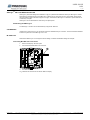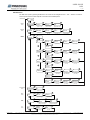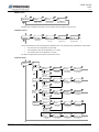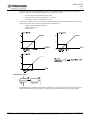
1
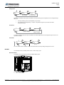
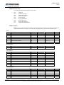
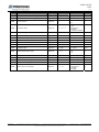
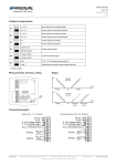
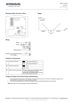
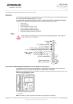
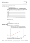
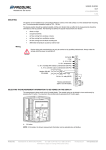
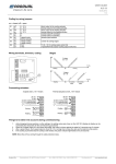
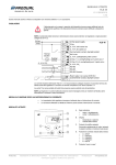
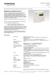
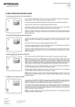
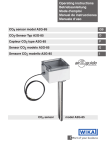
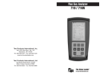
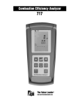
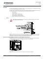
USER GUIDE HDH V1.0.0 (05.09.2013) 1 (8) MOUNTING The device can be installed in dry surroundings (IP20) by screws on the wall surface or on the standard flush mounting box. The recommended installation height is 150…180 cm. The device position should be selected carefully. All the error factors that can affect to the measurements should be eliminated as well as possible. The following list defines the typical measurement error factors. direct sun light occupant proximity air flow coming from windows or doors air flow coming from ventilation nozzles air flow coming from the flush mounting box differential temperature caused by external wall Wiring Device wiring and commissioning can only be carried out by qualified professionals. Always make the wirings while the power is switched off. NOTE: CO2 measurement causes a current peak to the supply voltage. This can produce an error to the analogue outputs when using long and thin cables. It is recommended to increase the wire cross section area in long cable situations (e.g. by using four-wire connection) to ensure reliable measurement signal. SELECTING THE MEASUREMENT INFORMATION TO BE VIEWED ON THE DISPLAY The measurement values scroll on the N model display. The wanted value can be locked to view continuously by pressing the S1 button. You resume to the scrolling view by pressing the S1 button again. A. S1 button NOTE: In M models, the shown measurement information can be selected also via Modbus. Produal Oy Keltakalliontie 18, 48770 Kotka FINLAND Tel: +358-10-219 9100 / Fax: +358-5-230 9210 Information is subject to change without prior notice. [email protected] www.produal.com USER GUIDE HDH 2 (8) ABCLogicTM SELF CALIBRATION FEATURE ABCLogic™ (Automatic Background Calibration Logic) is a patented self-calibration technique. ABCLogic™ method eliminates the possible long term drift. ABCLogic™ method can be used when the CO2 concentration drops at least two times within a week to the level of approx. 400 ppm. Therefore the ABCLogic™ is effective in spaces that are not continuously occupied. ABCLogic™ can be deactivated in continuously occupied spaces. Deactivating the ABCLogic™ The ABCLogic™ function can be deactivated by using the ML-SER tool. CALIBRATION If ABCLogic™ method is not in use, the device should be calibrated every 6-12 months. The recommended calibration interval is 5 years even if the ABCLogic™ is in use. ML-SER TOOL With the ML-SER tool you can change the device settings, controller and Modbus settings for example. Connecting ML-SER tool to the device 1. Remove the display / HD-AL3 option. 2. Connect the ML-SER cable to the connector. A. ML-SER cable CO2 measurement value shows on the ML-SER tool display. Produal Oy Keltakalliontie 18, 48770 Kotka FINLAND Tel: +358-10-219 9100 / Fax: +358-5-230 9210 Information is subject to change without prior notice. [email protected] www.produal.com USER GUIDE HDH 3 (8) ML-SER menu ML-SER menu opens by pressing the M button. The values can be changed with the ”+” and ”-” buttons. The menu is device-specific and the content depends on the device and installed options. Measurement 900 CO2ppm M Modbus menu OK OK COMMUNICATIONS M MODBUS ID 9.6 Baud rate (k) Modbus address [OFF / 1…247] Modbus speed [9.6 / 19.2 / 38.4] OK Calibration menu OK 1 Modbus ID OK OK On ABC-Logic Offset: CO2ppm CO2 tuning [±200 ppm] M Parity bit [None / Even / Odd] OK 0 Modbus ID CALIBRATION OK n Parity 0.0 Offset: °C ABCLogic calibration [On / Off] OK 0 Offset: %RH Temperature measurement tuning [±3,0 °C] Humidity measurement tuning [±5 %RH] OK Controller menu Cont OFF CONTROLLER +/- M OK Cont CO2 OK PI Modbus ID Control mode Control method [PI / P] +/- OK +/- OK OK 300 Integr. time s 700 CO2 Setpoint Integration time [50...5000 s] CO2 set point [400...2000 ppm] OK 500 CO2 Propor. band CO2 proportional band [100...2000] P Control mode Cont TEMPERATURE OK OK PI Modbus ID Control mode Control method [PI / P] +/- OK +/- OK 300 Integr. time s OK 21.0 °C Setpoint Integration time [50...5000 s] OK 2.0 °C Propor. band °C set point [18...26 °C] ° C proportional band [1,0...32,0] P Control mode Cont HUMIDITY OK OK PI Modbus ID Control mode +/- Control method [PI / P] OK P Control mode +/- OK Cont MAXIMUM CTRL OK 300 Integr. time s Integration time [50...5000 s] OK PI Modbus ID Control mode Control method [PI / P] +/- OK OK 50 %RH Setpoint %RH set point [0...100 %] OK OK 50 %RH Propor. band %RH proportional band [10...100] OK 300 Integr. time s 700 CO2 Setpoint Integration time [50...5000 s] CO2 set point [400...2000 ppm] OK 500 CO2 Propor. band CO2 proportional band [100...2000] P Control mode OK 21.0 °C Setpoint °C set point [18...26 °C] OK Potentiometer menu POTENTIOMETER OK OK 1100 ID Modbus 5 Hysteresis % Relay ON RELAY Relay switching point [400...2000 ppm] OK Hysteresis [0...100 % from range] OK 750 YELLOW AL3 5s OK 1.0.0 ID Modbus VERSION INFO OK M Keltakalliontie 18, 48770 Kotka FINLAND Software version OK 1250 RED Yellow indicator light illumination point [400...2000 ppm] M Produal Oy %RH proportional band [10...100] Y4 M Info menu %RH set point [0...100 %] OK 50 %RH Propor. band OK OK AL3 menu ° C proportional band [1,0...32,0] 50 %RH Setpoint Potentiometer output [OFF / Y3 / Y4] M Relay menu OK OK 2.0 °C Propor. band no RESET Red indicator light illumination point [400...2000 ppm] OK Reset to factory settings [no / yes] Tel: +358-10-219 9100 / Fax: +358-5-230 9210 Information is subject to change without prior notice. [email protected] www.produal.com USER GUIDE HDH 4 (8) Modbus menu OK OK 1 Modbus ID MODBUS ID COMMUNICATIONS Modbus address [OFF / 1…247] M OK OK 9.6 Baud rate (k) n Parity Modbus speed [9.6 / 19.2 / 38.4] Parity bit [None / Even / Odd] Modbus menu is available in M models. The bus settings can be changed through the menu. Calibration menu OK OK 0 Modbus ID CALIBRATION Offset: CO2ppm CO2 tuning [±200 ppm] M OK OK On ABC-Logic OK 0.0 Offset: °C ABCLogic calibration [On / Off] 0 Offset: %RH Temperature measurement tuning [±3,0 °C] Humidity measurement tuning [±5 %RH] All the measurements can be tuned through the calibration menu. The humidity tuning is available only in RH models. The CO2 value can be adjusted by 10 ppm steps. The temperature value can be adjusted by 0,1 °C steps. The humidity value can be adjusted by 1 % steps. ML-SER tool display shows how much the current value is tuned. Controller menu OK CONTROLLER M Cont OFF +/Cont CO2 OK OK PI Modbus ID Control mode Control method [PI / P] +/- OK +/- Cont TEMPERATURE OK Integration time [50...5000 s] OK PI Modbus ID OK 500 CO2 Propor. band CO2 set point [400...2000 ppm] +/- Control method [PI / P] OK P Control mode OK OK 300 Integr. time s Control mode CO2 proportional band [100...2000] Control mode +/- Control method [PI / P] OK P Control mode OK OK Control method [PI / P] OK ° C proportional band [1,0...32,0] OK 50 %RH Setpoint Integration time [50...5000 s] OK 50 %RH Propor. band %RH set point [0...100 %] %RH proportional band [10...100] OK OK 300 Integr. time s Control mode +/- OK 2.0 °C Propor. band °C set point [18...26 °C] 300 Integr. time s OK PI Modbus ID OK 21.0 °C Setpoint Integration time [50...5000 s] OK PI Modbus ID +/- Cont MAXIMUM CTRL OK 700 CO2 Setpoint P Control mode +/- Cont HUMIDITY OK 300 Integr. time s 700 CO2 Setpoint CO2 set point [400...2000 ppm] Integration time [50...5000 s] OK 500 CO2 Propor. band CO2 proportional band [100...2000] P Control mode OK 21.0 °C Setpoint °C set point [18...26 °C] Produal Oy Keltakalliontie 18, 48770 Kotka FINLAND OK OK 2.0 °C Propor. band 50 %RH Setpoint ° C proportional band [1,0...32,0] %RH set point [0...100 %] Tel: +358-10-219 9100 / Fax: +358-5-230 9210 Information is subject to change without prior notice. OK 50 %RH Propor. band %RH proportional band [10...100] [email protected] www.produal.com USER GUIDE HDH 5 (8) The control output can be controlled either according to a one measurement value or according to the maximum selection of all values. Humidity related settings are only available in RH models. The CO2 values can be adjusted by 10 ppm steps. The temperature values can be adjusted by 0,1 °C steps. The humidity values can be adjusted by 5 % steps. In the maximum selection control, the control output signal is formed according to the measurement that causes the largest control signal value. The following situation is in the example figure: Carbon dioxide concentration is 800 ppm Temperature is 21,5 °C Humidity is 55 % Potentiometer menu OK POTENTIOMETER M OK Y4 Potentiometer output [Off / Y3 / Y4] Potentiometer menu is available if HD-PU option is installed. You can select the potentiometer output connector and disable the potentiometer through the menu. The potentiometer is connected to the Y4 output as factory setting. Produal Oy Keltakalliontie 18, 48770 Kotka FINLAND Tel: +358-10-219 9100 / Fax: +358-5-230 9210 Information is subject to change without prior notice. [email protected] www.produal.com USER GUIDE HDH 6 (8) Relay menu OK OK 1100 ID Modbus Relay ON RELAY Relay switching point [400...2000 ppm] M OK 5 Hysteresis % Hysteresis [0...100 % from range] Relay menu is available if HD-R option is installed. The relay switching point and hysteresis can be changed through the menu. The relay switching point can be adjusted by 10 ppm steps. The hysteresis can be adjusted by 1 % steps. The hysteresis is given as per cents of the whole measurement range. AL3 menu OK OK OK 750 YELLOW AL3 1250 RED Yellow indicator light illumination point [400...2000 ppm] M Red indicator light illumination point [400...2000 ppm] AL3 menu is available if HD-AL3 option is installed. The indicator light limits can be changed through the menu. The hysteresis is 50 ppm. Info menu 5s OK 1.1.0 ID Modbus VERSION INFO M OK Software version OK no RESET Reset to factory settings [no / yes] You can check the device software version and reset the device to factory settings through the Info menu. MODBUS The parameter memory durability allows at least 1 million writing cycles. Bus termination The Modbus can be terminated by placing the MBUS TERM. jumper. A. Produal Oy MBUS TERM. jumper Keltakalliontie 18, 48770 Kotka FINLAND Tel: +358-10-219 9100 / Fax: +358-5-230 9210 Information is subject to change without prior notice. [email protected] www.produal.com USER GUIDE HDH 7 (8) Modbus function codes The device supports the following Modbus function codes. 0x01 Read Coils 0x02 Read Discrete Inputs 0x03 Read Holding Registers 0x04 Read Input Registers 0x05 Write Single Coil 0x06 Write Single Register 0x0F Write Multiple Coils 0x10 Write Multiple Registers 0x17 Read/Write Multiple Registers Modbus registers NOTE: If you try to write a parameter value that is beyond the parameter value range, the value will be replaced by the nearest acceptable value. For example, if you write 270 to the register 40011, the value will be replaced by 260. Coils Register Parameter description Data type Values Range Default 1 Y1 output overdrive activation Bit 0-1 0: Off, 1: On 0 2 Y2 output overdrive activation Bit 0-1 0: Off, 1: On 0 3 Y4 output overdrive activation Bit 0-1 0: Off, 1: On 0 4 Y3 output overdrive activation Bit 0-1 0: Off, 1: On 0 5 Relay overdrive activation Bit 0-1 0: Off, 1: On 0 6 Relay overdrive Bit 0-1 0: Off, 1: On 0 Discrete inputs Register Parameter description Data type Values Range 10001 Relay status Bit 0-1 0: Off, 1: On Values Range Input registers Register Parameter description Data type 30001 CO2 measurement Signed 16 400…2000 400….2000 ppm 30002 Temperature measurement Signed 16 0…500 0,0…50,0 °C 30003 Humidity measurement Signed 16 0…100 0…100 % 30004 Y1 output voltage Unsigned 16 0…1000 0,00…10,00 V 30005 Y2 output voltage Unsigned 16 0…1000 0,00…10,00 V 30006 Y3 output voltage Unsigned 16 0…1000 0,00…10,00 V 30007 Y4 output voltage Unsigned 16 0…1000 0,00…10,00 V 30008 Active potentiometer value Unsigned 16 0…1000 0,0…100,0 % Holding registers Register Parameter description Data type Values Range Default 40001 Y1 output overdrive Signed 16 0…1000 0…10.00 V 0 40002 Y2 output overdrive Signed 16 0…1000 0…10.00 V 0 40003 Y3 output overdrive Signed 16 0…1000 0…10.00 V 0 40004 Y4 output overdrive Signed 16 0…1000 0…10.00 V 0 40005 CO2 measurement tuning (offset) Signed 16 -200…200 -200…200 ppm 0 Produal Oy Keltakalliontie 18, 48770 Kotka FINLAND Tel: +358-10-219 9100 / Fax: +358-5-230 9210 Information is subject to change without prior notice. [email protected] www.produal.com USER GUIDE HDH 8 (8) Register Parameter description Data type Values Range Default 40006 Temperature measurement tuning (offset) Signed 16 -30…30 -3,0…3,0 °C 0 40007 Humidity measurement tuning (offset) Signed 16 -5…5 -5…5 % 0 0-1 0: P 1: PI 1 0-1-2-3-4 0: not in use 1: CO2 2: temperature 3: humidity 4: maximum selection 1 40008 Control method Signed 16 40009 Controller output 40010 Set point, CO2 Signed 16 400…2000 400….2000 ppm 700 40011 Set point, temperature Signed 16 180…260 18.0…26.0 °C 210 40012 Set point, humidity Signed 16 0…100 0…100 % 50 40013 Proportional band, CO2 Signed 16 100…2000 100….2000 ppm 500 40014 Proportional band, temperature Signed 16 10…320 1.0…32.0 °C 20 40015 Proportional band, humidity Signed 16 10…100 10…100 % 50 40016 Integration time Signed 16 50…5000 50…5000 s 300 40017 Active potentiometer output Signed 16 0-1-2 0: OFF 1: Y3 2: Y4 2 40018 Relay set point Signed 16 400…2000 400….2000 ppm 1100 40019 Relay hysteresis Signed 16 0…100 0…100 % 5 40020 Yellow AL3 indicator light illumination limit Signed 16 400…2000 400….2000 ppm 750 40021 Red AL3 indicator light illumination limit Signed 16 400…2000 400….2000 ppm 1250 0-1-2-3 0: CO2 1: temperature 2: humidity 3: scrolling 3 40022 Produal Oy Signed 16 Value shown on the display Signed 16 Keltakalliontie 18, 48770 Kotka FINLAND Tel: +358-10-219 9100 / Fax: +358-5-230 9210 Information is subject to change without prior notice. [email protected] www.produal.com