1
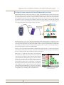
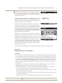
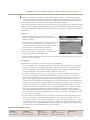
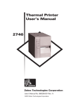
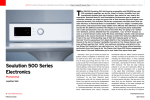
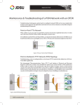
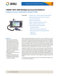
Application Note
Home Network Certification and Troubleshooting with SmartID™
Technology within the home is evolving quickly, while the home network remains unchanged it has proven to be
relatively robust and capable of handling new technologies, but it is also a source of many customer-impacting
problems. These problems are compounded when the installation or service technician is unable to adequately
test and troubleshoot the network, which often leads to repeat truck rolls. Cable companies and installation contractors are hungry for a way to comprehensively test the home network while keeping installation or service time
and equipment costs at a minimum.
Problem — Home network
The home coax network is considered the most troublesome, time-consuming portion of the cable network. It is most
susceptible to unauthorized, unskilled “modification,” and may have been installed by less-than-professional installers. Home network service calls and repeat visits are time-consuming, expensive, and make customers unhappy. The
need for service could be mitigated by thorough testing at the time of service installation; but (until now) testing the
home network comprehensively takes too much time to be practical. Many times, the recourse for a problem is to recable, which costs time and money.
In addition to these challenges, most home networks were installed before Multimedia over Coax Alliance (MoCA)
was invented, a technology that enables whole-home DVRs. This technology uses a frequency range beyond the
specifications of most home network components. The location of these components within the home is not always
clear. Consumer premises equipment (CPE) embedded diagnostics are insufficient to determine the exact location of
physical impairments or faulty components (the root cause of the problem).
New technologies, like MoCA, utilize an extended frequency range in the home network and present additional testing and troubleshooting challenges. Some MoCA meters address the test need by joining the MoCA network and
measuring such things as throughput. This provides incomplete results, as an indication of low throughput only indicates the existence of a problem, but does not show where the problem is located. Additionally, more information is
needed to determine the operating margin of the service.
Compounding these complications, technicians can only access the home network when the customer makes it available. Cable operators must make the most of every opportunity in which they have access to the subscriber premises
to comprehensively test this relatively inaccessible, troublesome portion of the network.
Solution — SmartID Advanced Coax Probes
The optimal solution is to test the complete home coaxial network for connectivity, frequency response throughout
the service frequency range, and susceptibility to ingress and impulse noise with JDSU SmartID Advanced Coax
Probes. These probes can map the home coax network very quickly giving installers or service technicians the location of any impairment. The solution makes it possible to simultaneously collect information about the network at
every outlet in the home, a process that would be prohibitively time-consuming using traditional means.
The SmartID system uses active probes that are attached to each outlet. When the test is activated, they communicate test and data signals throughout the network to qualify it for all services at once. The test is comprehensive and
consumes very little time, typically less than 2 minutes. This time savings enables technical operations to continue
moving toward higher productivity, lower operating expense, and higher customer satisfaction by concentrating on
this particularly costly segment of the service provider network.
WEBSITE: www.jdsu.com/test
Application Note: Home Network Certification and Troubleshooting with SmartID™
2
Testing the home network with SmartID Advanced Coax Probes
JDSU SmartID Advanced Coax Probes offer a method to quickly and comprehensively test a home network to verify
that it is ready for voice, video, and data services, including MoCA. The probes are testing transponders that transmit
test signals and data between each other on the network and consolidate analysis of the results on the technician’s
meter. Installation technicians conducting “walk-throughs” with customers can connect a probe to each outlet as Figure 1 illustrates. A probe, connected at the ground block or other point of entry (POE), is connected to the technician’s
digital service activation meter (DSAM). The technician initiates a test with the DSAM, the probes begin testing, and
in a couple of minutes the results are ready for analysis on the meter.
Figure 1. Example of an advanced coax probe connection
The following test process uses a test configuration that includes MoCA testing, but other test configurations can be
preprogrammed for implementation as applicable for the installation or service. The first step is to determine the presence of any radio frequency (RF) on the home network while it is disconnected from the hybrid fiber coax (HFC) plant.
Detected RF is presumed to be ingress; and, if the detected signal is specific to only one or two of the deployed probes,
the network point of ingress can be more quickly identified.
Next, the probes sweep and measure the 5 MHz to 1.6 GHz frequency range from point-to-point throughout the home
network. Each probe then performs frequency domain reflectometry (FDR) tests between each probe. The DSAM can
then process the measurement data to determine specifics about the network.
When the test is complete, the meter displays a test result matrix
that indicates the quality of the network connection between the
connected probes. The matrix contains both triple-play and MoCA
results. Impairments affecting the triple-play results are indicated
with an “X” appearing in the first column of the matrix and an
associated key on the left side of the display indicates which test
parameter failed, as Figure 2 shows. A check mark (✓) indicates that
the path has passed the test. The remaining columns on the right side
of the display show outlet-to-outlet network tests and are rated with
a MoCA Quality Index (MQI) from 0 to 10 that gauges the quality of
the connection, where 10 is the best and 0 is the worst. Passing scores
are highlighted in green and failing paths are highlighted in red.
Figure 2. Test matrix showing upstream failure
between probes R and A
Application Note: Home Network Certification and Troubleshooting with SmartID™
3
The technician can then drill down to see the topology of the home
network, as illustrated in Figure 3. This capability lets technicians
see the measured distance between the various outlets and the
components in the network.
Another display shown in Figure 4 shows the link between two probes,
including components and impairments, and helps technicians locate
impairments or faulty components by providing the length of cable
between the outlet or component and the fault.
In addition to detecting faulty components, loose connections, or
cable damage, an ingress test is also performed throughout the
operating range. If ingress is detected, the test will fail and show which
SmartID detected the ingress that measured above the threshold limit,
which is an indication of the source location. This capability enables a
more complete verification of the RF integrity of the network in much
less time than when using other methods.
SmartID probes provide a quick, comprehensive test of the home
network and do not require any CPE in order to test for network
transmission quality throughout the range of cable services,
including multi-room DVR using MoCA. Since all outlets are tested
simultaneously, the SmartID system will continue to reduce the
overall troubleshooting time spent per technician. A typical test with
five connected SmartID probes takes less than 2 minutes, which is
less time than it takes to perform a similar range of tests with other
equipment on just one outlet.
Figure 3. Example of network topology
Figure 4. Distance measurement
For more information on SmartID, take a look at the video, download the product brief, or visit the website.
Appendix
Step-by-step test process using SmartID
Configuration
1.Prior to the first test, each SmartID must be registered in the DSAM so that it can identify the probes during
the test and display information about the transmission performance between identified probes. The simple
process must only be performed once per probe. First, physically apply an alphabetical character label to each
probe. Next, put the DSAM in SmartID Registration mode and connect each probe one at a time via the USB
port. The user presses Add and enters the alphabetical character of the connected probe. The probe serial
number is stored permanently in the DSAM’s probe database, and the probe is now registered and ready to be
included in tests.
2.Service Plans — Service plans are pre-configured test plans with different frequency ranges and/or limits to
qualify for different service types. For example, there are three default service plans:
a.Drop Check is intended to test the drop cable from the tap to the ground block and covers the up and
downstream frequency ranges with an associated and appropriate loss-limit setting.
b.Voice-Video-Data is intended to test the home network and covers up and downstream frequencies but has
different loss limits than the Drop Check.
c.Voice-Video-Data-MoCA uses the same up and downstream limits but extends the test frequency range to
include MoCA frequencies.
Service plans can be created or modified and deployed using the Test Productivity Pack (TPP) server.
Application Note: Home Network Certification and Troubleshooting with SmartID™
4
3.Users can set frequencies in the meter or using TPP, with separate start and stop frequencies for upstream,
downstream, and MoCA. They can also set cable types and related velocity of propagation (VoP) in the meter
or using TPP. Default settings for RG6 and RG59 are preconfigured in the DSAM. VoP is a key parameter in
determining the distance to points in the network at which the impedance changes.
Note: When a MoCA filter is in place in the home network, the topology mapping function will always indicate
“ambiguous map” to notify that the instrument is unable to test at certain frequencies and that the results are based, to
some degree, on assumptions (when related to frequencies that cannot be tested because of the presence of the filter in
the network).
Test process
1.Connect a SmartID probe to each outlet in the customer
premises ensuring that all probes are powered on (indicated by a
blinking green light).
2.Disconnect the drop cable from the ground block (or other point
of entry) and connect a SmartID probe or other probe to the
ground block with a test lead. Ensure that the unit is powered on.
Connect the probe to the DSAM using a USB cable.
3.On the DSAM, go to Measurement » Basic » SmartID
4.Choose a service plan test configuration (customizable pre-set
frequency range and limits) with which to test.
5.Verify that all expected SmartIDs are detected and then review the results of the SmartID mode to determine
the next steps that are necessary.
Case examples
Here are a few real-world examples of troubleshooting success using SmartID:
1.A customer complained of picture tiling on signals in the high-end channel range that was not resolved after
multiple service calls. Previous unlucky guesswork led to replacement of the tap and to rewiring one side of
the house. Testing the home network with SmartID revealed that a splitter in the crawl space was unable to
pass high-end frequencies. The splitter was replaced and the issue was resolved.
2.A customer complained of picture tiling on a very popular sports channel at the high end of the frequency
range. The TV was installed on the wall in an entertainment room and connected to a post-construction
wall outlet. SmartID was used after two repeat service calls. The technician connected a probe to each outlet
where customer equipment was connected (five outlets). The SmartID test indicated that four of the five
connections passed. Fortunately, the one that failed was the one in the entertainment room. The SmartID test
results overview showed a connection issue, and the sweep display showed a frequency response problem at
750 MHz—a large suckout—about 30 dB deep and covering more than 20 MHz. The detail screen showed
multiple reflection events, one of which was only 7 feet from the problematic wall outlet. Quick investigation
uncovered an outlet, hidden behind a dresser, with an unexpected two-way splitter in it. The technician
removed the splitter and replaced it with a barrel splice. A fresh test revealed a good connection followed by a
check of the customer’s TV, which verified that the tiling problem was now resolved. The technician was in the
house a total of about 15 minutes.
3.In another tiling issue, SmartID was used to test the home network after two service calls. The test revealed
an unknown extra splitter in the basement. (The extra splitter was not obvious because there was a known
four-way splitter and four rooms with outlets. Apparently, one of the four-way splitter’s legs was not connected
to an outlet.) The newly discovered splitter was a cheap, low-quality variety that the technician replaced. On
another leg of the four-way splitter, the SmartID found a spliced-in poor-quality cable causing high-frequency
roll-off. This splitter was also replaced and the problems were fixed.
Test & Measurement Regional Sales
NORTH AMERICA
LATIN AMERICA
ASIA PACIFIC
TEL: 1 866 228 3762
FAX: +1 301 353 9216
TEL: +1 954 688 5660
FAX: +1 954 345 4668
TEL: +852 2892 0990
FAX: +852 2892 0770
Product specifications and descriptions in this document subject to change without notice. © 2012 JDS Uniphase Corporation
EMEA
TEL: +49 7121 86 2222
FAX: +49 7121 86 1222
www.jdsu.com
30173106 000 0212 SMARTID.AN.CAB.TM.AE
February 2012