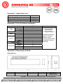
1
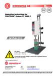
Operating Instructions for POLYVISC® FV flow-viscometer Voltage 4 x 1. 5 V Batteries This is a quality product of Luzernerstrasse 147a CH-6014 Luzern Schweiz Tel.: Fax: e-mail: +41-41-259 65 65 +41-41-259 65 75 [email protected] 1 INTRODUCTION .................................................................................................. 3 1.1 OPERATING INSTRUCTIONS........................................................................... 3 1.1.1 RANGE OF VALIDITY ..................................................................................... 4 1.1.2 TARGET AUDIENCE ...................................................................................... 4 1.2 ORGANISATIONAL MATTERS ......................................................................... 4 1.2.1 LOCATION OF THE OPERATING INSTRUCTIONS....................................... 4 1.2.2 MANUFACTURER AND CONTACT ADDRESS ............................................. 4 1.3 WARNING NOTICES ......................................................................................... 5 2 SAFETY ................................................................................................................ 6 2.1 SUMMARY ......................................................................................................... 6 2.2 SAFETY CONCEPT ........................................................................................... 6 2.2.1 INTENDED USE OF THE EQUIPMENT .......................................................... 6 2.2.2 IMPROPER USE ............................................................................................. 6 2.2.3 USER ROLES ................................................................................................. 7 2.2.4 DANGER AREA .............................................................................................. 8 2.2.5 AREAS OF RESPONSIBILITY ........................................................................ 8 2.2.6 GENERAL SAFETY RULES ........................................................................... 9 2.3 RESIDUAL DANGERS ...................................................................................... 9 2.4 WARNINGS........................................................................................................ 9 3 DESCRIPTIOIN OF LABORATORY EQUIPMENT ............................................ 10 3.1 PRINCIPLE OF MEASUREMENT .................................................................... 10 3.2 RANGE OF APPLICATION .............................................................................. 10 3.3 WORKINGMETHOD ........................................................................................ 11 3.4 ALTERING THE MEASUREMENT PERIOD .................................................... 12 3.5 TECHNICAL SPECIFICATIONS ...................................................................... 13 4 INSTALLATION .................................................................................................. 13 4.1 UNPACKING .................................................................................................... 13 5 MAINTENANCE ................................................................................................. 13 5.1 CLEANING ....................................................................................................... 13 5.2 SERVICE & CALIBRATION ............................................................................. 14 5.3 BREAKDOWN ................................................................................................. 14 6 TROUBLE SHOOTING....................................................................................... 15 7 GUARANTEE ..................................................................................................... 15 BA POLYVISC FV english / Edition 1.1 / 04.03.09 Page 2 von 16 1 INTRODUCTION This chapter gives information on the the structure of this document. It will assist you in making use of it and show how to find the required information quickly. 1.1 OPERATING INSTRUCTIONS Please read through these operating instructions before switching on or attempting to use the equipment. They describe the use of the POLYVISC PX-FV flow-viscometer, its installation and maintenance and the appropriate replacement parts and accessories. They will help you avoid erroneous use and consequent damage. Although POLYVISC machines are designed for ease of service, this does not release you from the obligation to inspect your equipment carefully and to clean it thoroughly. KINEMATICA AG is a specialist manufacturer of machines and equipment for dispersion and mixing technology. An important objective of these operating instructions is to fully inform you, the user, about the correct and safe use of our equipment. In order to achieve this, it is essential that you should carefully study chapter 2, “Safety”, and follow the instructions in this book. BA POLYVISC FV english / Edition 1.1 / 04.03.09 Page 3 von 16 1.1.1 RANGE OF VALIDITY The information in these operating instructions relates to the POLYVISC® identified as follows: Manufacturer: Product name: Type designation: KINEMATICA AG, CH-6014 Lucerne POLYVISC® POLYVISC® PX-FV flow-viscosimeter Article number Description 9400000 POLYVISC® PX-FV flow-viscosimeter 1.1.2 TARGET AUDIENCE These operating instructions are intended for all authorised users of our machines/equipment. We distinguish different user roles, taking account of the different demands placed on the user by the activity to be carried out. You will find the definitions of user roles with the demands on the user in chapter 2, “Safety”. You can fulfil one or more of these roles, provided that you meet the corresponding demands. 1.2 ORGANISATIONAL MATTERS If you are unable to find the answer to any question in the operating instructions, please contact the equipment manufacturer directly. 1.2.1 LOCATION OF THE OPERATING INSTRUCTIONS The operating instructions can only be of use to you if you always have them to hand. They should, therefore, always be kept at the place where the equipment is used. 1.2.2 MANUFACTURER AND CONTACT ADDRESS KINEMATICA AG Luzernerstrasse 147a CH-6014 Lucerne TEL: +41 41 259 65 65 FAX: +41 41 259 65 75 e-mail: [email protected] BA POLYVISC FV english / Edition 1.1 / 04.03.09 Page 4 von 16 1.3 WARNING NOTICES Please be aware of the meaning of the following warning signs: Safety instructions must be observed to ensure safe operation. This symbol indicates high voltage, with risk to health and environment. BA POLYVISC FV english / Edition 1.1 / 04.03.09 Page 5 von 16 2 SAFETY This chapter is directed at all users of KINEMATICA laboratory equipment. It includes information on safe and optimum use. 2.1 SUMMARY Any incorrect use of the installed equipment can be dangerous. Inadequately trained users can cause material damage and personal injury. This chapter informs you of the safety concept and the requirements for safe and optimum use of the equipment. All those authorised to operate, service and repair the equipment are required to study chapter 2, “Safety”. 2.2 SAFETY CONCEPT The safety concept sets down the entitlement to use the equipment and the responsibilities of the individual users. The machines and equipment are designed and constructed according to the state of the art and the recognised safety rules. 2.2.1 INTENDED USE OF THE EQUIPMENT The equipment is designed and constructed for the following use: The determination of flow characteristics of flowable and electroconductive fluids with a minimum viscosity of 6000 cP (mPa s) If you use the equipment for any purpose other than those listed, the manufacturer cannot be held liable for any resulting damage. 2.2.2 IMPROPER USE Any use other than the “proper use” without the written approval of the manufacturer or operation outside the technical limits of use is improper use. BA POLYVISC FV english / Edition 1.1 / 04.03.09 Page 6 von 16 2.2.3 USER ROLES To guarantee safety, we place requirements on the users of the equipment that must be met without fail. Only persons meeting the requirements are authorised to work with the equipment. We describe all those who work with the equipment as users. Since the requirements of these users are very much dependent on their activity, we distinguish the following user roles. Contract partner: The manufacturer can impose legal obligations on the contract partner when the equipment is purchased. The contract partner is obliged to ensure that the equipment is properly used. Operating company: The operating company ensures that the equipment is properly used and authorises persons who are entitled to work with the equipment in any one of the defined user roles. He is under the obligation to instruct the users. Note: Contract partner and operating company can be the same person. Service technician: The service technician is an employee of the operating company and looks after the equipment in special operating mode(s). He is a specialist with mechanical, electrical and electronic professional training. The service technician undertakes commissioning, decommissioning service and repair of the equipment. He must be appropriately trained to be able to carry out the service work required. Operator: The operator turns the equipment on and off. In the event of an alarm signal he informs the service technician. BA POLYVISC FV english / Edition 1.1 / 04.03.09 Page 7 von 16 2.2.4 DANGER AREA System/equipment The system danger area includes the whole system/equipment including the connecting lead and controls. Proximity danger area This refers to all areas within a defined distance of the equipment. User danger area This danger area includes all persons working with the equipment. 2.2.5 AREAS OF RESPONSIBILITY In order that the system/equipment can be used safely and without risk, the users in various roles bear the responsibility for particular danger areas. Contract partner: The contract partner bears the responsibility for the “proximity danger area”. Operating company: The operating company bears the responsibility for the “user danger area”. Only those users may be authorised to operate the system/equipment who fulfil all requirements of the user roles concerned. In so doing, attention must be paid to the following points: It is to be ensured that all users of the system/equipment have fully read and understood chapter 2, “Safety” and act accordingly in a safety-conscious manner. It is to be ensured that no unauthorised person carries out work with the system/equipment. It is to be ensured that users are informed of the possible risks and dangers connected with the system/equipment. It is to be ensured that those being trained or engaged in general training are under the permanent supervision of a trained and authorised person. Service technician: The service technician bears the responsibility for the “system/equipment danger area”. He ensures that the system/equipment is at all times free from technical faults, safe and functions correctly. BA POLYVISC FV english / Edition 1.1 / 04.03.09 Page 8 von 16 2.2.6 GENERAL SAFETY RULES Observe the following general safety rules: follow these operating instructions, in addition, observe the legal obligations and requirements for accident prevention and environmental protection of the country in which you operate the equipment, do not make any modifications to the equipment without the written authorisation of the manufacturer, only original replacement parts may be used for repairs, before any service work on the equipment, it must be ensured that the electrical supply is switched off, after any service, maintenance or repair work has been carried out on the system/equipment, it must be given a test run by the service technician. depending on the place at which it is installed, circumstances may require that hearing protection is worn when remaining in the vicinity of the equipment for long periods. 2.3 RESIDUAL DANGERS When the system/equipment is used in accordance with rules and regulations, residual dangers are minimal. RESIDUAL DANGERS Spillage of hot fluid. 2.4 Countermeasures Working carefully and wear protective clothing (goggles etc.) WARNINGS The POLYVISC flow-viscometer is suitable only for electroconductive fluids which have to be capable of flowing. The POLYVISC flow-viscometer is suitable for Product- Temperatures up to 80°C. Higher Temperatures may cause a damage. The POLYVISC flow-viscometer is not suitable for acidly and aggressive fluids. That means your fluid should be free of thinners and similar chemicals. See Appendix 2 for a detailed list of the chemical resistance of the housing-material ABS-V0 against common chemicals. CE-Sign KINEMATICA AG products comply with all the usual CE directives, carry the CE marking and are delivered with a corresponding declaration of conformity. BA POLYVISC FV english / Edition 1.1 / 04.03.09 Page 9 von 16 3 DESCRIPTIOIN OF LABORATORY EQUIPMENT With the POLYVISC® flow-viscometer you received a very easy-to-use and easy-tomaintain instrument to fast determine the flow-behaviour of electroconductive fluids. The Instrument is suitable for determination of flow-behaviour down to a minimumviscosity of 6000 mpas. To receive reproducibel results: 3.1 Always fill the complete reservoir of your medium being measured. Always place your instrument in the same horizontal orientation. Wherever applicable place it at same location. The accuracy of your measurement may depend on the electrical conductivity of your working-environment and the state of charge of the batteries. PRINCIPLE OF MEASUREMENT The POLYVISC®-instrument determines the area in the metering-box which the fluid will cover during the preset measurement-period. The obtained result will be displayed digital as an average flow-speed in [mm/sec]. This principle of measurement is capacitive, so that it is only suitable for electroconductive fluids. 3.2 RANGE OF APPLICATION The POLYVISC® flow-viscometer is made for the determination of the viscosity of fluids with uniformly distributed electrical conductivity and will be used for qualitycontrol in laboratory and fabrication. The battery-supplied instrument is easy- and read-to-use at any place at any time. Due to its mobility it can used directly on site, for example directly at the bottlingplant. For comparative measurements of viscosity using the POLYVISC® flow-viscometer, all capable-of-flow and thinner-free fluids with viscosity over 6000 mpas are are suitable. Based on the following diagram a rough calculation of mPa.s (cP) can be made. It shows sugar syrup at a measurement-period of 30 seconds. BA POLYVISC FV english / Edition 1.1 / 04.03.09 Page 10 von 16 3.3 WORKINGMETHOD 0. Activate the instrument using the mainswitch at the backside. „ 00 ^ „ is displayed. 1. The control-functions of the PV will be activated using the built-in magnet at the thicker side of the slider. Activate the POLYVISC®-MeasuringSystem by moving the slider along the left side of the housing where “ON” is written. The result of the last measurement will be displayed automatically. If the instrument has been turned off for a long time using the main-switch, the last result will not be displayed any more. Instead “???” will be displayed. 2. To select the measurement-period, move the slider to the right side of the housing (7.5, 15, 30 secs). The position of the bar in the indicator field marks the chosen measurement-period. 3. Place the slider in the mounting-groove of the flow channel. The POLYVISC® is now ready for measurement (display 00, tolerance 00 - 10). BA POLYVISC FV english / Edition 1.1 / 04.03.09 Page 11 von 16 4. Fill in the product to be measured. For reproducible results always use the same batch-size and keep the POLYVISC® as horizontal as possible. 5. Activate the measurement by pulling out the slider fast and evenly. 6. When the selected measurement-period is up, the result will be displayed during approx. 10", 7. 3.4 then the display switches off automatically. If the product to be measured has already reached the end of the flow channel before the selected measurement-period is up, a shorter measurement-period should be selected. ® Emptying and cleaning of the POLYVISC . The flow channel must be completely dry. To check this, place the slider in the flow groove of the flow channel. If the display does not indicate 00 (tolerance 00 - 10), dry the appliance thoroughly using warm air. When you finished your series of measurement, turn the main-switch of to save batterypower. ALTERING THE MEASUREMENT PERIOD Measuring times between 10 seconds and 10 minutes can be individually set on the DIL switch. To do this, carefully open the battery compartment on the underside of the POLYVISC® and swing the battery out without breaking contact with the points. DIL-1 DIL-2 DIL-3 DIL-4 DIL-5 DIL-6 DIL-7 DIL-8 ON calibration light-diode (LED) "ON" operative measuring time "ON" measuring range 10 - 20 secs measuring range 20 - 40 secs measuring range 40 - 80 secs measuring range 80 - 160 secs measuring range 160 - 320 secs measuring range 320 - 640 secs OFF calibration light-diode (LED) "OFF" operative measuring time "OFF" Warning The switches 3 to 8 can only be used when the measuring switch is on. A measuring time of 60 seconds is to be selected. Observe the following instructions step by step and alter the DIL switch positions with a small screwdriver. 1. 2. 3. 4. 5. DIL-1 ON calibration-LED is switched on DIL-2 ON operating control of measuring times (7,5/17/30 secs) is switched off DIL-5 ON measuring range 40-80 secs is switched on Place calibrating potentiometer in an average setting Begin measuring time by inserting and extracting the sliding attachment in the flow channel 6. The LED is illuminated during the measuring time. Determine the exact length with a stop watch and set the calibrating potentiometer at 60 secs (to the right +/to the left -) 7. DIL-1 OFF calibrating LED is switched off 8. place batteries in the right position and completely close the battery compartment. Your POLYVISC® is now ready for measurement for a duration of 60 seconds. In case of other individual measuring times follow the same procedure. BA POLYVISC FV english / Edition 1.1 / 04.03.09 Page 12 von 16 3.5 TECHNICAL SPECIFICATIONS POLYVISC® FV flow-viscometer Voltage Ambient Temperature max. Productemperature max. Humidity Protection Class Working Time Min. Viscosity of Medium being measured Housing-material Dimensions Weight 6 x 1.5 V - Batteries 40 °C 80 °C 90 % IP 54 continuous working approx. 6000 mpas acrylic butadiene styrene (ABS-V0) 114 x 57 x 325 mm 900 g 4 INSTALLATION 4.1 UNPACKING Open the dispatch box and check that the contents agrees with the delivery note. Check all parts for possible transport damage. Inform us or your dealer immediately of any disagreement or fault. 5 MAINTENANCE 5.1 CLEANING The POLYVISC® flow-viscometer can be easily cleaned using lukewarm water. Avoid mechanical cleaning with rough brushes. Never use the slider for cleaning. Never immerse the instrument completely in water. The pressure may weaken the gaskets, so that water may enter and damage electronic components BA POLYVISC FV english / Edition 1.1 / 04.03.09 Page 13 von 16 5.2 SERVICE & CALIBRATION The POLYVISC® flow-viscometer requires a regular and thorough cleaning but no special maintenance. Only the batteries have to be exchanged when down. The display of the instrument shows in these cases: <BAT> . The POLYVISC® flow-viscosimeter is a measuring instrument, which however, does not work according to internationally acknowledged norms. The displayed measurement results are not absolut values of viscosities but values of flowspeeds for comparative measurement. The POLYVISC® is applied for many different products as a measuring instrument. In order to comply with the requirements of the ISO-quality management system, the unit has to be regularly checked and calibrated if needed. Checking To check the measuring results you can use an internal reference liquid. When an error of measurement of ± 10 % is reached, we suggest a new calibration. Calibration This can only be done by the producer or a specially equipped KINEMATICA Service-Center. For each calibration a test certificate is issued. We suggest a yearly calibration. 5.3 BREAKDOWN The POLYVISC® flow-viscometer is a very reliable instrument. However, it is possible that in certain cases some faults might occur. For instance, the instrument is made of many electronic components and is therefore susceptible to blows. Should the instrument breakdown for any reason, only the producer or a specially equipped KINEMATICA Service-Center can repair it. BA POLYVISC FV english / Edition 1.1 / 04.03.09 Page 14 von 16 6 TROUBLE SHOOTING PROBLEM REASON SOLUTION Display shows Channel is dirty Clean the channel and repeat the measuring TROUGH DYRTY and Measurement stops Display shows "BAT Battery-Voltage 4x1,5V" after is low. activation No displayed data visible Display or electronics may be damaged. Change the batteries. When changing will take to much time, the stored last result and the selected measurement-period will be lost and has to be reset. LAST RESULT will be displayed as “???”. Changing batteries does not affect any calibration Send the equipment to the nearest authorised KINEMATICA AG service centre or directly to KINEMATICA AG 7 GUARANTEE KINEMATICA AG guarantees that the equipment that it produces will run free of any fault related to materials or manufacturing faults for 12 months. If thorough testing shows a fault to be due to either of the above causes, KINEMATICA AG guarantees that the equipment will be repaired or replaced free of charge. The guarantee does not cover parts that are subject to normal wear. It is void if any person other than an employee of KINEMATICA AG or their appointed representative has made modifications to the equipment or if the damage is due to failure to comply with the operating instructions, to carelessness, accident, incorrect use or incorrect supply voltage. KINEMATICA AG reserves the right to make technical changes to the equipment without modifying equipment delivered earlier in the same way. In the event of technical problems, for spare parts requirements or for advice, contact our regional appointed agent, your preferred dealer or us directly at: KINEMATICA AG Luzernerstr. 147a CH-6014 Lucerne Switzerland BA POLYVISC FV english / Edition 1.1 / 04.03.09 Tel. +41-41-259 65 65 Fax +41-41-259 65 75 e-mail [email protected] Page 15 von 16 Appendix 1: Spare-Parts List Part 4 x Batterien 1.5 V Gasket for Battery-Box Slider ID-No. 9305749 9340420 9850014 Appendix 2: List of chemical resistance Chemicals weak acids strong oxidising hydrofluoric acid strong base weak alcohols esters solvents ketones aether halogen alkene benzene patrol fuels & oils benzine mineral oil Grade of Resistance ++ 0 --++ ++ -----++ 0 ++ “- -“ =no resistance “-“ =mean resistance “0” =limited resistane “+” =good resistance “++”=very good resistance This table shows the grade of chemical resistace of the housing-material ABSV0 against common chemicals. Appendix 3: Dimensions & ID-No. POLYVISC FV Assemby Group Main Identification Order No. Production-No. POLYIVISC FV POLYVISC FV 9400000 9400000 Product-Identification POLYVISC FV Standard-Version ® POLYVISC is registred Trademark of KINEMATICA AG Luzern, SWITZERLAND BA POLYVISC FV english / Edition 1.1 / 04.03.09 Page 16 von 16