1
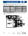
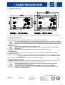
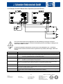
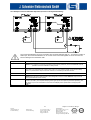
P33G1D02-050202.doc
Operating Instructions “AKKUTEC”
(NBPA 2440-P33G1)
Placing in operation and maintenance only by suitably qualified personnel!
The operating instructions are to be read prior to usage or installation of the AKKUTEC, the
information given is to be observed! In the case of failure to observe the information given, all rights
under the warranty may be lost!
Safety Instructions
♦ Power supply for protection class I and enclosure rating IP20. Operation only in dry rooms
♦ Observe applicable VDE regulations, in particular VDE 0100 and EN 60204!
♦ The surrounding air temperature range is to be observed!
♦ To prevent overload of the DC output circuit, the circuit is to be protected externally with a fuse!
(Value see Section 3.1)
♦ Only the battery types specified for the unit are permitted to be used!
♦ Battery replacement is only to be made with the unit unpowered! (See Section 10)
♦ On the connection of external backup batteries, battery protection must be provided by the user! In
this case the protection components (overload and short circuit protection!) must be installed as
close as possible to the set of batteries for safety reasons
♦ On the usage of batteries, sufficient air flow in accordance with VDE 0510, part 2 must be ensured.
♦ Never connect together new and used batteries, or batteries of different types, or from different
manufacturers!
♦ Dispose of used batteries in an environmentally responsible manne!!
1. Concise Description
The battery backed up DC power supply in the AKKUTEC range uses the standby-parallel principle of operation and, in
conjunction with a lead accumulator, ensures that the DC power supply is reliably maintained in the case of a mains power
failure.
The power supply has the following features:
•
•
•
•
•
Switched primary, switched power supply with I/V charging characteristic
Microcontroller-based battery management
Temperature compensation for charging voltage by means of external sensor module (optional module)
Display and control panel for switch cupboard door installation or surface mounting (option)
TEC bus with RS 232-Interface optional module
2. Standards and Regulations
Safety of power transformers, power supply units and similar
Particular requirements for transformers for switch mode power
supplies
Optocouplers for protective separation against electric shock,
requirements - tests
EMC
Overall unit
EN61558 2-17 (VDE 0570 2-17)
VDE 0884
EN 55011 / 1998 limit class A Group 1
EN 61000-3-2 and EN61000-3-3 limit class A
EN50082-2 / 1995
EN 50178 / EN60950
cULus-Listed (UL508 / CSA 22.2), File E237077
Industrial Control Equipment
2VD5
-1Adresse:
Helmholtzstrasse 13
D-77652 Offenburg
Postfach 2327
D-77613 Offenburg
Tel. +49 / (0)781 / 206- 0
Fax +49 / (0)781 / 25318
www.j-schneider.de
[email protected]
Subject to technical change !
Geschäftsführer:
Karl Schneider, Dipl.-Ing. (FH)
Bettina Schneider, Dipl.
Betriebswirt (BA)
Rolf Anti Dipl.-Wirt.-Ing. (FH)
Amtsgericht Offenburg HRB 758
P33G1D02-050202.doc
3. Technical Data
3.1 Electrical Data
Rated Input Voltage
Input Voltage Range
400-500V AC
360V - 550V ↔
400V-10% - 500V+10%
Input Frequency
Rated Input Current
45 – 65 Hz
2,75A AC (400V AC)
2,2A AC (500V AC)
Max. Switch On Current
Output Voltage
65A / 5ms, i²t = 14A²s
a) 19.8...26.4V DC
b) 19.8..28.6V DC
(during activated boost
charging or temperature
compensation)
Final Charging Voltage
Charging Characteristic
Deep Discharge
Protection and Load
Shedding at
Nominal Output Current
Constant Current Limiting
Battery Type
26,4 V DC ±0,4%
I/U DIN 41773-1
19,8V DC ±0,4%
40A DC
1,05...1,1xI ANenn
Pb battery, maintenancefree
Efficiency
Ua=26.4V DC, Ia=Nenn
and Ue=400V AC
Max. Power Loss
‘worst-case’
Earth Leakage Current
Fuse Protection, Primary
Fuse Protection DC
Output Circuit
Fuse Protection Battery
Load Circuit, Secondary
Type of Connector,
Primary
‘Netz’ (Mains)
Type of Connector,
Secondary
‘Ua’, ‘Batt’
Type of Connector,
Interface
‘IO-1...IO-3’
Type of Connector
Current-Share-Bus ‘CS’
91,5% (typ.)
Fehler’ (Fault)
Red LED
LED illuminates on:
• Battery operation
(‘Netzbetrieb’ (Mains
Operation) LED goes out
in this case)
• UA fault
• Battery circuit open or
high resistance (test
interval 60s)
• Battery weak
• Battery poles reversed
• Battery over temperature
(only in conjunction with
temperature
compensation)
115W
<3,5mA
3 x 4 A slow (extern)
40 A slow (extern)
40 A slow (extern)
Combicon screw terminal
2
2.5mm
Tightening torque 0,5-0,6Nm
clamp 10mm
2
Tightening torque 1,2-1,5Nm
Combicon screw terminal
2
1.5mm
Tightening torque 0,22-0,25Nm
clamp 10mm
2
Tightening torque 0,5-0,6Nm
3.2 Indicators
‘Netzbetrieb’ (Mains
Operation)
Green LED,
LED illuminates on:
• Mains operation, i.e.
(UE>UEmin and TInt<TIntmax)
Green LED
(Battery voltage within the
monitoring window, i.e.
21.6< UBatt < 27V DC)
Green LED
(Battery voltage above the
monitoring window, i.e. U Batt
=27V DC
-2Adresse:
Helmholtzstrasse 13
D-77652 Offenburg
Postfach 2327
D-77613 Offenburg
Tel. +49 / (0)781 / 206- 0
Fax +49 / (0)781 / 25318
www.j-schneider.de
[email protected]
Subject to technical change !
Geschäftsführer:
Karl Schneider, Dipl.-Ing. (FH)
Bettina Schneider, Dipl.
Betriebswirt (BA)
Rolf Anti Dipl.-Wirt.-Ing. (FH)
Amtsgericht Offenburg HRB 758
P33G1D02-050202.doc
3.3 Operation
Connection IO-2
(option interface)
External display and control panel for the display of operating parameters and for setting
the device parameters (option)
3.4 Signal Inputs and Outputs
‘Netzbetrieb’ (Mains Operation)
1)
‘Fehler’ (Fault)
1)
1)
Floating relay contact, normally open, m ax. contact load 30V DC/ 0.5A
Floating relay contact, changeover, max. contact load 30V DC/ 0.5A
Floating relay contact, normally open, max. contact load 30 V DC/ 0.5A
1)
Floating relay contact, normally open, max. contact load 30 V DC/ 0.5A
Shut-Down
‘Starkladung’ (Boost Charging)
Shut down of the UPS mode
Switched input referenced to earth, switching level: 24V DC (16 -80V DC)
Activation of boost charging (boost charging voltage 28.6V DC)
Switched input referenced to earth, switching level: 24V DC (16 -80V DC)
1)
The signal contacts are coupled to LEDs (see Section 3.2). The illumination of an LED thus results in the energisation of
the corresponding relay.
3.5 General
Weight
Individual Module
Storage Temperature
Operating Temperature
Enclosure Rating
Dimensions B x H x T
Approx.. 3,3kg
Recommended 0...30°C,
Permissible 0...50°C
Recommended 10...20°C
(battery life!),
Permissible 0...40°C
IP20
fixation
Fixation bar according to
DIN EN 50022-35
Alternative: Adapter kit for
the direct fixation on the
mounting plate
290 x 180 x 147 mm
See Section 9
4. Installation
The battery backed up DC power supply is to be installed such that the necessary cooling is provided. A minimum
separation of ≥75mm to neighbouring equipment or assemblies in the area of the ventilation openings is to be maintained.
The installation is always to be made such that sufficient air circulation through the unit can be ensured.
All fastening points are always to be use d to fix the unit. During installation, the unit is to be covered in the case that swarf
from drilling can fall on or in the unit. ( Risk of short circuit!)
-3Adresse:
Helmholtzstrasse 13
D-77652 Offenburg
Postfach 2327
D-77613 Offenburg
Tel. +49/(0)781/206-0
Fax +49/0)781/25318
www.j-schneider.de
[email protected]
Geschäftsführer:
Karl Schneider,Dipl.-Ing.(FH)
Bettina Schneider Dipl.Betriebswirt (BA)
Rolf Anti Dipl.-Wirt.-Ing.(FH)
Amtsgericht Offenburg HRB 758
Subject to technical change !
P33G1D02-050202.doc
5. Connection
Prior to connection, the values for the mains voltage and frequency are to be checked against the values on the rating
plate. Connect in accordance with the labels on the connecting terminals. (See main block diagram and connector
assignments). Unused connecting terminal screws are to be tightened.
Anschluß:
Mains Input Voltage
‘Starkladung’ (Boost Charging)
Control Input
Signal Contact ‘Fehler’ (Fault)
(Sammelstörmeldung)
Signal Contact ‘Netzbetrieb’ (Mains
Operation)
Control and Display Panel
Connecting terminal
‘IO-1’ 4
Connecting terminal
5=NC, 6=NO, 7=COM
Connecting terminal
‘IO-1’ 8, 9
Connecting terminal
‘IO-2’ 1, 2
Battery Current Measurement
Connecting terminal
(optional module)
‘IO-3’ 1, 2
Signal Contact Battery Voltage Above Connecting terminal
‘IO-3’ 3, 4
Signal Contact Battery Voltage Within Connecting terminal
‘IO-3’ 5, 6
Klemme:
Connecting terminal
DC Output (loads)
Pb Battery
Battery Temperature Sensor
(optional module)
Current Share Bus
(in case of parallel connection of
several modules)
Shut-Down Control Input
‘Netz’ (Mains) L, N,
Connecting terminal
‘Ua’
+, Connecting terminal
‘Batt’ +, Connecting terminal
‘IO-1’ 1, 2
Connecting terminal
‘CS’ 1
Connecting terminal
‘IO-1’ 3
In the case of overload, the DC output current comprises the maximum charging rectifier cur rent as well
as the current from the battery. To prevent overload of the DC output circuit, the circuit is to be protected
externally ! (Value see Section 3.1)
-4Adresse:
Helmholtzstrasse 13
D-77652 Offenburg
Postfach 2327
D-77613 Offenburg
Tel. +49 / (0)781 / 206- 0
Fax +49 / (0)781 / 25318
www.j-schneider.de
[email protected]
Subject to technical change !
Geschäftsführer:
Karl Schneider, Dipl.-Ing. (FH)
Bettina Schneider, Dipl.
Betriebswirt (BA)
Rolf Anti Dipl.-Wirt.-Ing. (FH)
Amtsgericht Offenburg HRB 758
P33G1D02-050202.doc
6. Placing In Operation
The unit is switched on by the application of the mains supply.
The battery voltage must match the nominal voltage of the charging rectifier!
Never reverse the poles of the battery!
Never short circuit batteries! Risk of arcing!
Check the connections for correctness prior to switching on for the first tim e
Only make electrical connections with the unit unpowered
7. Operation
Approx. 2s after the switch on of the mains, the output voltage is enabled and the loads connected supplied with power. The
back up battery is also charged. This operating mode is indicated by the illumination of the green ‘Netzbetrieb’ (Mains
Operation) LED.
By removing the mains voltage, or if the input voltage drops below the minimum, the AKKUTEC switches over to battery
mode. The battery mode is indicated by the illumination of th e ‘Fehler’ (Fault) LED. The ‘Netzbetrieb’ (Mains Operation) LED
is not illuminated in this case.
The illumination of an LED always results in the energisation of the corresponding signal relay. (See block diagram, Section
5)
The ‘Fehler’ (Fault) LED has a centralised fault indication function. The individual causes of malfunctions are described in
Section 3.2.
7.1 Battery Circuit Monitoring
To check the capability of the UPS to provide back up, the battery circuit is tested cyclically at intervals of 60s; the first test
is performed 60s after mains switch on. By means of this test it is possible to identify an open circuit or the high resistivity of
the battery circuit. A defective battery circuit is indicated by the simultaneous illumination of the ‘Fehler’ (Fault) and
‘Netzbetrieb’ (Mains Operation) LEDs (centralised fault indication).
7.2 Battery Test
During mains operation, a cyclic battery test loads the battery whilst the voltage is measured. In this way it is possible to
evaluate the quality of the battery. A seriously aged battery is indicated by the simultaneous illumination of the ‘Fehler’
(Fault) and ‘Netzbetrieb’ (Mains Operation) LEDs (centralised fault indication)
The battery test is used to detect seriously aged batteries. To evaluate the backup capacity of the
batteries with this system, it is imperative that a manual battery check is performed from time to
time! (See Section 11)
7.3 Boost Charging
In exceptional cases, it may be required to boost charge lead batteries. Duri ng this process the final charging voltage (and
thus also the output voltage!) is increased from 26.4V to 28.6V. Boost charging is activated by applying a +24V DC control
voltage to connection 4 on the ‘IO -1’ terminal strip, and remains activated until the control voltage is removed again.
Boost charging results in the operation of the batteries in the gassing area and can be used to
reactivate deep discharged or sulphated batteries. The boost discharge mode should only be
used on open, non-maintenance-free batteries and must only be performed for a limited period.
The usage of boost charging in conjunction with closed, maintenance -free batteries is not
permitted, as here damage can be caused to the batteries!
7.4 Shut-Down
To avoid discharging the backup batteries to the deep discharge limit unnecessarily, it is possible to shut down battery
operation early. This is performed by applying a +24V DC control voltage to connection 3 on the ‘IO -1’ terminal strip.
-5Adresse:
Helmholtzstrasse 13
D-77652 Offenburg
Postfach 2327
D-77613 Offenburg
Tel. +49 / (0)781 / 206- 0
Fax +49 / (0)781 / 25318
www.j-schneider.de
[email protected]
Subject to technical change !
Geschäftsführer:
Karl Schneider, Dipl.-Ing. (FH)
Bettina Schneider, Dipl.
Betriebswirt (BA)
Rolf Anti Dipl.-Wirt.-Ing. (FH)
Amtsgericht Offenburg HRB 758
P33G1D02-050202.doc
7.5 Temperature Compensation (optional module)
Lead batteries have a temperature coefficient of approx. -4mV per °C and cell. The AKKUTEC final charging voltage is
selected such that battery charging is provided over a temperature range of 15 -40°C.
In applications with frequent and large temperature variations, the charging voltage should be appropriately compensated to
achieve optimal battery life. Also, particularly in the case of very low surrounding air temperatures (Tu < 15°C),
compensation should be performed to ensure adequate b attery charging.
By connecting the external temperature sensor module (option) to terminal strip ‘IO -1’ connection 1 and 2 (note poles!),
temperature compensation is automatically activated. For an surrounding air temperature variation of 0 -40°C, the final
charging voltage (and thus also the output voltage) varies over a range of 27.3 - 26.2 V DC
Battery temperatures above 45°C are indicated by the simultaneous illumination of the ‘Fehler’ (Fault) and ‘Netzbetrieb’
(Mains Operation) LEDs
F
To obtain satisfactory battery life, the operating temperature of the batteries should not exceed
20°C. Higher temperatures lead to a drastic reduction in the life!
7.6 Control and Display Panel (optional module, can be connected to AKKUTEC equipment
using the option interfaces IO-2 and IO-3)
Particularly in larger battery system, it is often desired to display equipment parameters, e.g. battery voltage, load current,
battery current, error messages, etc. and to make parameter settings.
To meet these requirements, a spec ial door mounting display and control panel is available. This panel has an illuminated
LC display and a keypad (setting parameters and operation). The panel is connected to the IO -2 interface using two cables.
7.7 Battery Current Measurement (optional module, can be connected to AKKUTEC equipment
using the option interfaces IO-2 and IO-3)
To measure the battery current (charging and discharging current), an appropriate current measurement transducer is
required that is inserted in the battery cable. With the aid of the Control and Display Panel described in Section 7.6, the
battery current can then also be indicated on the display.
8. Taking Out of Operation
The unit is taken out of operation by removing the mains supply. To prevent subsequent backup from the batteries, the
battery circuit must be opened by activating ‘Shut -Down’. (See Section 7.4) The ‘Netzbetrieb’ (Mains Operation) and ’Fehler’
(Fault) LEDs must go out.
Never undo electrical connections whilst the unit is in operation!
It also not permitted to make electrical connections whilst the unit is in operation!
-6Adresse:
Helmholtzstrasse 13
D-77652 Offenburg
Postfach 2327
D-77613 Offenburg
Tel. +49 / (0)781 / 206- 0
Fax +49 / (0)781 / 25318
www.j-schneider.de
[email protected]
Subject to technical change !
Geschäftsführer:
Karl Schneider, Dipl.-Ing. (FH)
Bettina Schneider, Dipl.
Betriebswirt (BA)
Rolf Anti Dipl.-Wirt.-Ing. (FH)
Amtsgericht Offenburg HRB 758
P33G1D02-050202.doc
9. Installation Drawings
To attach the AKKUTEC module directly on the mounting plate you can purchase optional mounting flanges.
10. Battery Replacement
Battery replacement is only permitted to be performed by authorised service personnel!
It is to be ensured that the battery poles are connected correctly. In the case of batteries connected
with the poles reversed, battery charging and battery enable d uring mains failure is inhibited, this is
indicated by the simultaneous illumination of the ‘Netzbetrieb’ (Mains Operation) and ’Fehler’ (Fault)
LEDs.
Never short circuit batteries! Risk of arcing and burns !
Never connect together new and used batteries, or batteries of different types, or from different
manufacturers !
Used batteries are to be disposed in an environmentally responsible manner !
11. Maintenance
To ensure adequate backup capacity of the power supply, the capacity of the b atteries should be checked at regular
intervals of 3 to 6 months.
Checking the battery: Force battery operation by switching off the mains. The batteries must achieve the required bridging
time under nominal conditions. When the deep discharge limit is reached, the AKKUTEC switches
off automatically.
The unit is to be cleaned at least once a year, depending on the degree of soiling.
12. Special Operating Modes
The AKKUTEC is suitable for master-slave operation as well as for redundant operation. The require d operating mode is
defined by the setting of the parameters in the unit and the external circuit (see below).
The parameters in the AKKUTEC units are set with the aid of the Control and Display Panel
(optional module) via the IO-2 interface.
If no control panel is available at the user, the modules can also be purchased with the
parameters set appropriately in the factory. The parameters set can be seen on the additional
label on the front of the module!
-7Adresse:
Helmholtzstrasse 13
D-77652 Offenburg
Postfach 2327
D-77613 Offenburg
Tel. +49 / (0)781 / 206- 0
Fax +49 / (0)781 / 25318
www.j-schneider.de
[email protected]
Subject to technical change !
Geschäftsführer:
Karl Schneider, Dipl.-Ing. (FH)
Bettina Schneider, Dipl.
Betriebswirt (BA)
Rolf Anti Dipl.-Wirt.-Ing. (FH)
Amtsgericht Offenburg HRB 758
P33G1D02-050202.doc
12.1 Example Circuit for Master-Slave Operation (Increased Power).
In the case of the master-slave configuration, the internal battery reverse pole connection
protection is ineffective. Reverse connection of the battery results, unavoidably, in damage to the
loads and the AKKUTEC units!
F
To exploit the maximum effectiveness from the active current distribution, the “ -Ua cabling”
between the two modules should be made as symmetrical as possible (cable length, cable cross section).
Component Label
K1
D
F1
F2
F3
G
A1
A2
R
Comment
24V DC battery circuit contactor with switching current I ≥ 30A DC
Free-wheeling diode for battery circuit contactor
Attention! Never operate the contactor without a free-wheeling diode! Operation without a free-wheeling diode
can result in irreparable damage to the AKKUTEC module
Fuse protection for battery circuit contactor
Battery circuit protection
Attention! The protection components (overload and short circuit protection!) are to be installed as close as
possible to the set of batteries for safety reasons
Attention!
In the case of an overload the DC output current is the sum of the charging rectifier current and the battery
current. To protect the DC output circuit from overload, it is necessary to use external fuses.
Backup battery
AKKUTEC module with standard parameter settings. The complete sampling of the signal inputs and outputs is
performed via the master module . (See also Section 3.4) For the connections for the Control and Display Panel,
please refer to the appropriate handbook!
AKKUTEC module with special parameter settings as ‘Slave Module’. The centralised fault indication signal from
the slave module should be evaluated separately. (Selective fault localisation)
Loads
-8Adresse:
Helmholtzstrasse 13
D-77652 Offenburg
Postfach 2327
D-77613 Offenburg
Tel. +49 / (0)781 / 206- 0
Fax +49 / (0)781 / 25318
www.j-schneider.de
[email protected]
Subject to technical change !
Geschäftsführer:
Karl Schneider, Dipl.-Ing. (FH)
Bettina Schneider, Dipl.
Betriebswirt (BA)
Rolf Anti Dipl.-Wirt.-Ing. (FH)
Amtsgericht Offenburg HRB 758
P33G1D02-050202.doc
12.2 Example Circuit for Redundant Operation (Increase in the System Reliability)
The connections labelled 2 on the IO -2 interface are connected internally with Ua -. To avoid the creation of
earth loops, the connections labelled 2 on IO -2 must not be connected together! A connec tion here can
result in damage to the AKKUTEC units !
Component Label
F1 / F2
Comment
Protection of the battery circuit 1 and battery circuit 2
Attention! The protection components (overload and short circuit protection!) are to be installed as close as
possible to the set of batteries for safety reasons
F3
Attention!
In the case of an overload the DC output current is the sum of the charging rectifier current and the battery
current. To protect the DC output circuit from overload, it is necessary to use external fuses.
G1 / G2
D
Backup batteries
Decoupling diode module
Attention! The decoupling diode module must be designed for the sum of both AKKUTEC output currents
(80 A)! (Overload/short circuit current!)
AKKUTEC module with special parameter settings as ‘Redundant Module 1’ (ID code 0) as well as ‘Redundant
Module 2’ (ID code 1) The complete sampling of the signal inputs and outputs is performed separately. (See
also Section 3.4) For the connections for the Control and Display Panel, please refer to the appropriate
handbook!
Loads
A1 / A2
R
-9Adresse:
Helmholtzstrasse 13
D-77652 Offenburg
Postfach 2327
D-77613 Offenburg
Tel. +49 / (0)781 / 206- 0
Fax +49 / (0)781 / 25318
www.j-schneider.de
[email protected]
Subject to technical change !
Geschäftsführer:
Karl Schneider, Dipl.-Ing. (FH)
Bettina Schneider, Dipl.
Betriebswirt (BA)
Rolf Anti Dipl.-Wirt.-Ing. (FH)
Amtsgericht Offenburg HRB 758

![Solaris LC40 [v04]](http://vs1.manualzilla.com/store/data/006347096_1-050cff7c0b4f91b9fb35d753454c0152-150x150.png)


![[U4.92.11] Procédure ENGENDRE_TEST](http://vs1.manualzilla.com/store/data/006367543_1-7a8bc9bbf5b71ba531fd386dd19da1a3-150x150.png)