1
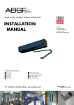
Operating Instructions
Air-On® Individual room air conditioner AKLKK-900
Item no. 002061_00/03.2014
www.air-on.ch
Table of contents
1
General Information................................................................................7
1.1
2
3
Intended use........................................................................................................................................7
1.3
EC Declaration of Conformity .......................................................................................................7
1.4
Disposal .................................................................................................................................................7
Safety Instructions...................................................................................9
2.1
Explanation and Structure..............................................................................................................9
2.2
Information on safe use ............................................................................................................... 11
2.3
Installation......................................................................................................................................... 13
2.4
Commissioning................................................................................................................................ 13
2.5
Operation........................................................................................................................................... 14
2.6
Warranty terms and liability exclusion ................................................................................... 14
Your Air-On® ......................................................................................... 15
3.1
4
6
Device overview .............................................................................................................................. 15
Functions ................................................................................................ 17
4.1
5
Target group........................................................................................................................................7
1.2
Your room air quality .................................................................................................................... 17
4.2
Functional principle ....................................................................................................................... 18
4.3
Separate functions ......................................................................................................................... 19
4.4
Your Air-On® in the course of the year ................................................................................. 24
Operation................................................................................................ 25
5.1
Operating concept ......................................................................................................................... 25
5.2
Overview of the operating elements....................................................................................... 26
5.3
Operating element, Standby ...................................................................................................... 27
5.4
Switching the device On/Off ...................................................................................................... 27
5.5
Device drying mode ...................................................................................................................... 28
5.6
Setting the nominal temperature value................................................................................. 29
5.7
Operating the modes.................................................................................................................... 30
5.8
Comparison of the operation modes ..................................................................................... 31
5.9
Status displays ................................................................................................................................. 32
Care and Cleaning ................................................................................ 35
6.1
AKLKK-900
Clean the device surfaces with a moist cloth....................................................................... 35
Air-On AG – Table of contents
5
7
8
9
Maintenance........................................................................................... 37
7.1
Maintenance schedule.................................................................................................................. 37
7.2
Read code.......................................................................................................................................... 38
7.3
Error codes ........................................................................................................................................ 39
7.4
Cleaning the filter ........................................................................................................................... 39
7.5
Filter, replace .................................................................................................................................... 43
Options .................................................................................................... 45
8.1
Humidification module................................................................................................................. 45
8.2
KNX-TP interface card................................................................................................................... 46
Troubleshooting.................................................................................... 47
9.1
10
Customer service ............................................................................................................................ 47
9.2
Faults according to symptoms (without error message) ................................................ 48
9.3
Error code .......................................................................................................................................... 49
9.4
Vent the water circuit in the device......................................................................................... 50
Technical Data........................................................................................ 51
10.1
General data ..................................................................................................................................... 51
10.2
Type plate .......................................................................................................................................... 54
Index of key words ............................................................................... 55
Imprint ..................................................................................................... 59
6
Air-On AG – Table of contents
AKLKK-900
1
General Information
1.1 Target group
This document is intended for persons that:
•
•
are in immediate contact with the device (users of the climatised room)
are responsible for the maintenance of the device (user/caretaker/maintenance supervisor)
1.2 Intended use
Your Air-On® must only be used for the purpose intended by the manufacturer. Any other or
use beyond this is termed as not intended use.
Keep these operating instructions in a safe place for future reference.
1.3 EC Declaration of Conformity
You can find the Declaration of Conformity on our homepage at:
www.air-on.ch/konformitaetserklaerung
1.4 Disposal
Packaging
Packaging material must be recycled and disposed of correctly.
De-installation
The device must only be de-installed by a service partner.
Disposal
Device and replacement parts must be disposed of correctly according to applicable national
legislations.
The active carbon filter must be packed in a plastic bag and disposed of with the normal rubbish.
AKLKK-900
Air-On AG – General Information
7
8
Air-On AG – General Information
AKLKK-900
2
Safety Instructions
2.1 Explanation and Structure
Safety instructions are intended to avert possible risks wen using the device.
Structure
The safety instructions in this document are structured as follows:
1
i
Note
3
Incorrect cleaning agent may damage the device
Never clean the device with aggressive and scouring
cleaning agents.
Clean the device only with a moist cloth.
2
4
1
Safety signs
3
Type and source of the danger
2
Signal word
4
Impacts and measures
Meaning and use
The safety instructions in this document are classified as follows:
Designates a potentially hazardous situation
Not avoided this may lead to mortal or severe injuries.
Warning
AKLKK-900
Air-On AG – Safety Instructions
9
Designates a potentially hazardous situation
Not avoided this may lead to minor injuries.
Caution
Designates a potentially harmful situation
i
If not avoided, the device or something in its vicinity will be damaged.
Note
Additional notes
Support
The "Hint" designates additional information that assist you in using the
Hint
10
device.
Air-On AG – Safety Instructions
AKLKK-900
2.2 Information on safe use
Risk of injury from mechanical and electrical components
Warning
Inside the device, there are components that are live and that are moved
mechanically which can lead to injuries or death when touched.
Never attempt to open, change, disassemble or dismantle the device at locations not intended for that purpose in any other way!
Risk of explosion
Inflammable or corrosive gases, vapours or dust may ignite.
Warning
If inflammable or corrosive gases are determined, the device must be
switched off immediately.
Risk from moisture
Liquids entering may damage the device or cause a short-circuit that, if
Warning
touched, can lead to severe injuries or even death.
Prevent liquids from entering:
•
•
never put plants on or above the device so that water ingress when
watering is avoided.
never wash the device with too much water or a soaking wet cloth. Use
only a moist cloth.
Make sure that no water in air inlets or outlets enters the facade (do not spray
the facade, protect against rain water).
Unauthorised use
This device is not designed to be used by persons (including children) with
Warning
restricted physical, sensory, or mental capabilities or with lack of experience
and/or knowledge unless they are supervised by a person who is responsible
for their safety and have received instructions from this supervising person in
how the device should be used.
AKLKK-900
Air-On AG – Safety Instructions
11
Children
There is a risk of injury when using the device incorrectly. Children should be
Warning
supervised in order to ensure that they do not play with the device.
Ventilation blades
Fans are located behind the ventilation blades that rotate at high speed, and
Caution
electric filters that are operated with high voltage. If not operated correctly,
these can lead to injury or electric shock. Never stick objects in the device
openings!
Risk of falling
Injuries may result if the device is misused as a climbing or stepping aid.
Caution
Never stand on the device and never use the device as a climbing or stepping
aid.
Missing or used active carbon filter results in too high
ozone concentrations
Caution
An ozone concentration that is too high poses a risk to health.
Never operate the device without active carbon filter, and always replace it in
time.
LED check when opening the doors and covers
If the opening of one of the doors or covers is not detected, there is a risk of
Caution
injury.
When opening the service doors or covers of the bottom inlet or top outlet
respectively, the user must check if the respective LED illuminates on the
status display.
If the LEDs do not illuminate, an error is at hand. Then you have to close the
doors/covers and contact your service partner (see page 47).
Example: service
doors open
12
Air-On AG – Safety Instructions
AKLKK-900
2.3 Installation
Incorrect installation
i
Note
Incorrect installation may damage the device.
The device must only be installed by a trained fitter according to the national
in accordance with the national installation regulations.
Wall outlet
Installing the device under a wall socket incorrectly could lead to risk from the
Warning
wall socket overheating.
The device must not be installed/operated immediately underneath a wall
socket.
Bath/shower
An electric shock may result from making contact with live sources that could
Warning
be lethal or lead to severe injuries.
The device must be installed in such a manner that it cannot be touched by
the person in the bath/shower.
Defective mains connecting line
An electric shock could be lethal or lead to severe injuries when making conWarning
tact with a defective mains connection line.
If the mains connection line of this device is damaged, it must be replaced by
the service partner.
2.4 Commissioning
Incorrect commissioning
i
Note
AKLKK-900
Incorrect commissioning may damage the device.
The device must only be commissioned by a trained fitter.
Air-On AG – Safety Instructions
13
2.5 Operation
Damage from accumulation of air
i
Note
Damage can be caused to the device if the correct air circulation cannot be
guaranteed, e.g., by a thick airtight curtain.
Never cover the device. It is forbidden to place textile materials or other
materials and objects on the device, or to block the air inlets at the bottom
and on the right side.
The device is intended for mounting on the wall. The following distances must be maintained
to ensure for optimum air circulation during operation:
A
A
A
A:
Recommended positioning 10 cm from floor. Access from right, left and right
must be guaranteed (recommended min. 5 cm)
You must be able to access the main switch at all times (see page 15 Device overview
Position 2).
2.6 Warranty terms and liability exclusion
The warranty terms and liability exclusion for the Air-On® device are subject to the general
terms of business of Air-On AG. You can find this on our homepage at:
http://www.air-on.ch/agb
14
Air-On AG – Safety Instructions
AKLKK-900
3
Your Air-On®
3.1 Device overview
5
7
6
8
9
10
4
3
2
11
1
16
152
14
13
12
1
Radiant panel
9
2
Main switch
10 Cover of the outdoor air electric filter
3
Control panel
11 Service doors
4
Active carbon filter
12 Water tank (optional)
5
Blade outlet
13 Humidification module (optional)
6
Service display
14 Secondary air blade inlet
7
Outdoor air electric filter
15 Room air coarse filter
8
Outdoor air coarse filter
16 Room air electric filter
AKLKK-900
Outgoing air coarse filter
Air-On AG – Your Air-On®
15
16
Air-On AG – Your Air-On®
AKLKK-900
4
Functions
4.1 Your room air quality
Heating – ventilation – air purification – dehumidification - humidification: everything in one
device!
The intelligent control regulates the three central influencing factors in a demand-oriented and
energy-saving way for a healthy room climate.
•
•
•
CO2 -concentration
Humidity
Temperature
Temperature [°C]
Air-On® always keeps these three physical quantities in the optimum desired range, provides
an ideal, comfortable climate for humans and effectively filters fine particles, ultrafine, allergens
and pollen particles out of the air. This ideal comfortable climate in combination with the relation between temperature and relative humidity, are summarised in a so-called area of comfort
that contains all factors for well-being.
Relative air humidity [%]
The area of comfort in which the temperature and humidity is perceived as being pleasant.
AKLKK-900
Air-On AG – Functions
17
4.2 Functional principle
1
8
2
11
9
5
3
4
10
6
7
Functional principle as device cross-section
1
Supply air (cleans, conditions the air with 6
Heating water supply/return lines
outdoor air quantity)
7
Condensation
2
Exhaust air
8
Sensors (temperature, CO2, humidity)
3
Outdoor air
9
Thermoelectric heat pump
4
Secondary air
10 Humidification and dehumidification
5
Radiant heat
18
Air-On AG – Functions
AKLKK-900
4.3 Separate functions
Air-On® is the only device with an integrated silent heating pump for individual room conditioning. These and other superior technologies make each of the individual functions to an
excellent module of healthy indoor environment.
heating
Using convection, the Air-On® device brings the room to the desired temperature quickly and efficiently. At the same time, the radiating surface on the
front side ensures for a pleasant warmth.
Depending on the heating demands, the integrated thermoelectric heat pump
of the Air-On® is switched on automatically.
1
2
1
Thermoelectric heat pump
AKLKK-900
2
Air flow in heat mode
Air-On AG – Functions
19
Ventilation
The room is supplied with cleaned outdoor air according to demand, thus,
CO2, temperature and humidity controlled. This is pre-heated or pre-cooled
by the exhaust air via a heat exchanger.
A possible icing of the heat exchanger by unfavourable temperature conditions indoors and outdoors is prevented effectively by the Air-On® device.
3
2
1
1
Outdoor air
2
Exhaust air
20
3
Air-On AG – Functions
Cleaned and odour-neutralised supply air
AKLKK-900
Cleaning the air
Outdoor air and indoor air are cleaned by the Air-On® device effectively in
three filter levels (coarse filter, electrostatic filter and active carbon filter).
In this manner, the room air and the outdoor air supplied are cleaned from
fine particles, in particular also ultrafine particles, allergens, pollen and
unpleasant odours.
The Air-On® device efficiently reduces ozone to a level that is safe according to the WHO. The
active carbon filter does not only bind ozone that is produced by the electrostatic filters in the
device and ensures for hygiene in the device. It also reduces ozone that is contained in the outdoor air in high concentrations during the summer months.
2
1
3
1
Electric filter module
2
Active carbon filter
AKLKK-900
3
Air flow in air cleaning mode
Air-On AG – Functions
21
Dehumidification
The dehumidification takes place in perfect interaction with the gentle cooling.
As soon as the outdoor and room air is cooled below the dew point by the
decentral thermoelectric heat pump in cooling mode, it looses humidity. This
supports the cooling function as the perception of temperature is associated
with the humidity.
In heating mode, the room is dried by air supplied from outside.
1
2
1
22
Thermoelectric heat pump
Air-On AG – Functions
2
Air flow in dehumidification mode
AKLKK-900
Humidification (optional)
An additional humidification of the room air may make sense for an optimum
room climate depending on demand and season. For this purpose, Air-On®
devices are available with and without humidification module; this can be retrofitted as an option at any time.
Normal tap water can be used in a convenient manner for the energy saving
and hygienic ultrasonic atomisation. In doing so, a demineralisation cartridge ensures that no
lime is released in the form of harmful ultrafine particles.
3
1
2
1
Water tank
2
Humidification module
AKLKK-900
3
Air flow in humidification mode
Air-On AG – Functions
23
4.4 Your Air-On® in the course of the year
The device operates in different combinations of the individual functions which are each activated automatically depending on the time of year.
WINTER
Symbol
24
SPRING
Function
SUMMER
Symbol
AUTUMN
Function
Humidification
Only active in winter
and partially in the transitional period.
Cleaning the air
Active throughout the
year.
heating
Only active in winter
and partially in the transitional period.
Dehumidification
Only active in summer
and partially in the transitional period.
Ventilation
Active throughout the
year.
In some cases
Possible in the transitional period but only
necessary in some
cases.
Air-On AG – Functions
AKLKK-900
5
Operation
5.1 Operating concept
Your Air-On® is self-cleaning. The device is provided with information from the environment
and by the user (absence, guest, night, cold, warm, etc.) and sets itself automatically. Depending on the operating mode, different influence variables (CO2 content, temperature, humidity,
fan level) are evaluated and the individual functions are controlled by the intelligent Air-On®
regulation that a pleasant room climate desired by the user is always created.
AKLKK-900
Air-On AG – Operation
25
5.2 Overview of the operating elements
1
2
DOOR
WATER SERVICE FAULT
3
4
5
1
Standby indicator
4
Operation modes control panel
2
Status displays
5
Control panel temperature specification
3
Mini view of the device with status
localisation
26
Air-On AG – Operation
AKLKK-900
5.3 Operating element, Standby
The operating element switches to standby after not being touched for 10 seconds. All LEDs go
out and only the standby indicator (1) continues to illuminate.
Exception: when in operating mode Party (see page 31) as well as if an error or service message
illuminates in the status display (2) and an LED illuminates on the miniature view of the device
(3), the operating element cannot switch to standby until the message has been acknowledged.
In order to reactivate the operating element, you can tap on a sensor button (temperature or
operating mode selection) (4/5).
5.4 Switching the device On/Off
The main switch is positioned on the left side behind the device and should only be operated
for maintenance purposes or with possible malfunctions.
Switch on the device
•
In order to switch on the device, move the rocker switch to 1, and to 0 for switching off.
Avoid the formation of mould in the room
In order to prevent the accumulation of mould during longer periods of
Hint
absence, we recommend that the Air-On® is never switched off.
Device drying during longer standstill periods
i
Note
AKLKK-900
Residual moisture can lead to the formation of mould.
If the device is taken out of service for longer periods, it is absolutely
necessary to carry out the device drying mode.
Air-On AG – Operation
27
5.5 Device drying mode
If the device is going to be switched off and taken out of service for longer periods (longer
than one week), the device drying mode must be carried out in all cases in order to guarantee
hygiene in the device.
In case your device is equipped with the option humidification, first decommission the humidification module before starting the device drying according to chapter 8 (see page 45).
Start the device drying
The device drying is started when pressing the < and + buttons at the same
time.
The correct starting of the device drying is indicated by the 4 symbols
flashing at the same time.
The noise of the fan increases at the same time.
In case your device is equipped with the option KNX, take note that the device drying must be
started separately on each device. Starting the device drying via KNX for all devices at the same
time is not possible.
Device drying completed
The complete device drying takes 3 hours. The completion of the device drying is indicated by
the 4 symbols lighting up continuously at the same time.
As soon as the 4 symbols light up, the device automatically switches to the window opening mode. Now it can
be switched off manually using the main switch (see
page 27).
The device is dried out hygienically perfectly and can be switched off for longer periods without problem.
28
Air-On AG – Operation
AKLKK-900
5.6 Setting the nominal temperature value
By tapping on the “+/-“ buttons, you can regulate your individual room temperature. The LED
of the level set illuminates blue.
•
•
Tap on the “+” button to increase the room temperature.
Tap on the “-” button to reduce the room temperature.
Control panel temperature specification
Optimum operation
When changing the temperature, different device-internal factors are
Hint
adapted. This takes a little time. For this reason, the temperature should only
be adjusted in small steps: switch maximum one to two levels higher or lower
each time.
AKLKK-900
Air-On AG – Operation
29
5.7 Operating the modes
Your Air-On® device operates in five different performance levels, the so-called operating
mode:
•
•
•
•
•
Absent
Silent
Comfort
Party
Window opening
In doing so, the device regulates the room climate depending on the season, humidity and
temperature.
When tapping on the arrow buttons, you can change the operating mode step
by step from the left to the right
or vice-versa.
30
Air-On AG – Operation
AKLKK-900
5.8 Comparison of the operation modes
Operating mode «Absent»
This operation of the Air-On® is optimised for a low energy consumption
(power and water) at the cost of a higher noise level.
Ideal for uninhabited premises.
Operating mode «Quite»
The night mode is optimised for minimum noise emission. In doing so, the
Air-On® still ensures for a good climate for one to two persons.
Ideal for sleeping.
Operating mode «Comfort»
The device automatically reacts to different requirements (temperature
indoors/outdoors, humidity indoors/outdoors, CO2 concentration in the room
air) and ensures for a good room climate. Odour development and energy efficiency are treated in a balanced manner.
Ideal for operating during the day or with brief absence.
Operating mode «Party»
The fan as well as the filter run constantly at high performance thus enabling a
good and healthy room climate despite high loading. Compared with normal
operation, the noise level is increased.
Ideal if there are many persons, odour-intensive beverages, etc.
AKLKK-900
Air-On AG – Operation
31
Operating mode: «Window opening»
This mode switches the heating, ventilation and air cleaning function off temporarily. The room climate is intended exclusively for the open window. The
device only have self-protection against frost risk.
Ideal when opening the window or when the device should be absolutely quiet.
You can switch on the operating mode "Window opening" on by pressing the
left arrow button again in the operating mode "Absence".
Displays “Absent” and “Quite” both illuminate.
5.9 Status displays
DOOR
WATER SERVICE FAULT
Status display example: “Service doors open”
Three levels of messages are shown in the status display:
1
Messages for the user (open doors, water tank empty, etc.).
2
Service messages for maintaining the device (see page 37).
3
Error messages for troubleshooting for the service partner (see page 47).
32
Air-On AG – Operation
AKLKK-900
User messages
Status
DOOR
DOOR
DOOR
WATER
AKLKK-900
Miniature view
Cause
Action
Service doors are
missing or are not
mounted correctly.
Mount the service
doors correctly.
Blade for the outlet is
missing or not
mounted correctly.
Mount the blade
correctly.
Blade for the room air
inlet is missing or not
mounted correctly.
Mount the blade
correctly.
Humidification
module water reservoir is empty.
Fill up the water reservoir in the
humidification
module.
Air-On AG – Operation
33
34
Air-On AG – Operation
AKLKK-900
6
Care and Cleaning
6.1 Clean the device surfaces with a moist cloth
Clean the device surfaces
•
Wipe over the surface of the device with a moist cloth.
i
Note
AKLKK-900
Incorrect cleaning agent may damage the surfaces of
the device
Never clean the device with aggressive and scouring cleaning agents.
Clean the device only with a moist cloth.
Air-On AG – Care and Cleaning
35
36
Air-On AG – Care and Cleaning
AKLKK-900
7
Maintenance
Maintenance by the user
Manipulation to the device may lead to injuries.
Caution
The user may only carry out the maintenance tasks listed in this chapter.
In event of incorrect handling, also by third parties, will lead to all guarantee
and warranty claims being cancelled.
7.1 Maintenance schedule
Status display
SERVICE
Miniature view
Activity
Frequency
Clean the room air electric filter module.
every 6 months or
earlier in event of
high contamination
Automatic acknowledgement of the service
notification after
cleaning.
Clean the outdoor air
electric filter module.
SERVICE
SERVICE
ERROR
AKLKK-900
every 6 months or
earlier in event of
high contamination
Automatic acknowledgement of the service
notification after
cleaning.
Order a filter set. Replace
active carbon filter and
both coarse filters.
1 x per year
The service notification
goes out automatically
after replacement.
Maintenance necessary:
Read off the error code
from the service display
(see page 38).
Contact your service
partner
(see page 47).
-
Air-On AG – Maintenance
37
7.2 Read code
Service and error messages that the user cannot rectify themselves are designated with a code.
The code for the service partner is read as follows.
Description
1
Remove service doors (1).
1
2
Remove the water tank (2) (only if your
device is equipped with this option).
2
3
38
Read code.
Air-On AG – Maintenance
AKLKK-900
7.3 Error codes
Status display
Miniature view
ERROR
Activity
Display code
Maintenance necessary:
Read off the error code
from the service display.
Contact your service
partner (see page 47).
7.4 Cleaning the filter
Room air electric filter
Room air electric filter, removal
1
Using handle shell (2), push the service
doors (1) to the right, hang out and
remove.
2
1
2
Push the blades (3) to the right and
remove.
3
Pull out the room air electric filter
module (4) parallel to the front on both
5
tabs (5).
4
Clean the electric filter in a non-trade
dishwasher with the filter attachment
pointing upwards.
AKLKK-900
3
4
Air-On AG – Maintenance
39
Clean the electric filter module in the dishwasher
Place the electric filter with coarse filter in the dishwasher pointing wards to
Hint
ensure that no contamination can accumulate in the filter. Do not wash any
sensitive dishes together with the electric filter module.
Clean the electric filter module in the sink
As an alternative, the filter can be cleaned in the sink. Take care that when the
Hint
filter is cleaned in the sink, it is not covered in soap and/or scrubbed, but that
it is only rinsed in lukewarm water under the tap.
Then the filter must be dried in the air or in a cold flow of air (e.g., hair drier).
Error due to moisture
i
Note
Residual wetness in the electric filter module can lead to faults in the device.
The electric filter module may only be reinstalled in the device in a dry state.
Residual moisture may still be at hand, in particular, in the struts of the plastic
parts as well as in the coarse filter net. The drying can, if required, be sped up
by using an absorbent lint-free cloth without applying mechanical pressure
(external dabbing).
40
Air-On AG – Maintenance
AKLKK-900
Outgoing air coarse filter
Outgoing air coarse filter, removal
1
Using handle shell (2), push the service
doors (1) to the right, hang out and
remove.
2
1
2
Pull the outgoing air coarse filter (3) to
the front.
3
Clean the filter in a non-commercial
dishwasher or rinse under a tap with
lukewarm water and then dry well.
3
AKLKK-900
Air-On AG – Maintenance
41
Outdoor air electric filter module
Outdoor air electric filter module, removal
1
Using handle shell (2), push the service
doors (1) to the right, hang out and
remove.
2
1
2
Pull the cover of the outdoor air electric
filter (3) to the front.
3
Pull the outdoor air electric filter (4) to
the front using the handle shell (5).
4
5
Clean the electric filter in a non-trade
dishwasher with the filter attachment
pointing upwards
3
4
Clean the electric filter module in the dishwasher
Place the electric filter with coarse filter in the dishwasher pointing wards to
Hint
42
ensure that no contamination can accumulate in the filter.
Air-On AG – Maintenance
AKLKK-900
Clean the electric filter module in the sink
As an alternative, the filter can be cleaned in the sink. Take care that when the
Hint
filter is cleaned in the sink, it is not covered in soap and/or scrubbed, but that
it is only rinsed in lukewarm water under the tap.
Then the filter must be dried in the air or in a cold flow of air (e.g., hair drier).
Error due to moisture
i
Note
Residual wetness in the electric filter module can lead to faults in the device.
The electric filter module may only be reinstalled in the device in a dry state.
Residual moisture may still be at hand, in particular, in the struts of the plastic
parts as well as in the coarse filter net. The drying can, if required, be sped up
by using an absorbent lint-free cloth without applying mechanical pressure
(external dabbing).
7.5 Filter, replace
The Air-On® device outputs a message as soon as it is necessary to change the active carbon
filter and both electric filter attachments (coarse filter).
For replacing the active carbon filter and electric filter attachment, a complete filter set can be
ordered from Air-On AG or your service partner (see page 47). A detailed instruction as to how
the filter is replaced is included in the filter set.
The active carbon filter and the filter attachments must be replaced at least once a year. The
device outputs a respective message.
Spare filter set, ordering
i
Note
AKLKK-900
The spare filter set can be ordered from your service partner.
The instructions for changing the filter is enclosed in the FS-AKLKK-900 filter
set.
Air-On AG – Maintenance
43
44
Air-On AG – Maintenance
AKLKK-900
8
Options
8.1 Humidification module
The Air-On® device can be equipped or retrofitted with a humidification module. It can be
ordered from your service partner (see page 47) and also be installed by them. A more detailed
installation and operating instruction is enclosed in the packaging.
Ordering the humidification module
i
Note
AKLKK-900
The humidification module can be ordered from your service partner.
The installation instruction is enclosed with the module.
Air-On AG – Options
45
8.2 KNX-TP interface card
Protection
and
safety
Automation
and
remote access
Sun protection
and blind
control
Operation
and
visualisation
Lighting
control
Energy
management
Heating
ventilation and air
conditioning
control
An Air-On® device can be connected to an KNX network via a KNX interface and thus, be integrated into a building management system. This allows the Air-On® device to be operated in
the different function ranges from KNX.
KNX can be used to control the heating, lighting, roller blinds, ventilation and security technologies across buildings and demand-oriented.
A separate installation manual is available on out homepage (www.air-on.ch/knx) for the installation of the KNX interface card as well as for commissioning and programming.
46
Air-On AG – Options
AKLKK-900
9
Troubleshooting
9.1 Customer service
You have to contact the service partner to assist with troubleshooting. You can find the contact
data behind the service doors on the cover of the outdoor air electric filter.
Contact address in the device
1
Remove service doors (1).
2
The contact address (2) is located on
the electric filter cover.
2
1
AKLKK-900
Air-On AG – Troubleshooting
47
9.2 Faults according to symptoms (without error message)
Symptom
Possible cause
•
Hissing noise
•
•
Gurgling/rustling noise in
the water circuit
Standby indicator does
not illuminate, no function
Standby indicator illuminates, the control panel is
dark
Standby indicator illuminates, no function of the
device
48
•
•
Soiled electric filter causes discharging
The electric filter was not dried
completely by the dishwasher
Climatic conditions may also
lead to discharge
Air in the water circuit
Main switch not
switched on
Measures
•
•
•
•
•
•
No mains voltage
•
•
Display in energy saving mode
•
•
One or more covers are open
(status display "Door" is
illuminated)
Air-On AG – Troubleshooting
•
Clean the electric filter
module in the dishwasher
and re-insert (see page 39).
Remove the electric filter
module, dry completely
and reinsert.
If there is a hissing noise
after carrying out the
measures described, establish contact with the service
partner.
Vent the water circuit in the
device (see page 50).
Switch the main switch on
(standby indicator is
green).
Check the power supply.
Press any button to activate the display.
Close all doors and covers.
AKLKK-900
9.3 Error code
Status display
Miniature view
Activity
Display code
Error:
Read off the error code
from the service display
(see page 38).
ERROR
Contact your service
partner (see page 47).
Meaning of the error codes
Error code on the service display
Possible cause
20
•
21
•
22
•
25...99
•
AKLKK-900
Measures
Lack of water in the external
heating system.
Service has not been carried
out on the outdoor air electric
filter.
Service has not been carried
out on the room air electric
filter.
Device error.
•
•
•
•
Rectify the lack of water in
the central heating (consult
the service partner / heating engineer).
Clean the electric filter
immediately (see page 42).
Clean the electric filter
immediately (see page 39).
Contact your service partner (see page 47).
Air-On AG – Troubleshooting
49
9.4 Vent the water circuit in the device
Vent the water circuit
1
Remove service doors (1).
1
2
Remove the water tank (2) (only if your
device is equipped with this option).
•
The venting screw is located at the top
left on the device.
2
3
Turn the venting screw (3) open by a
half a turn counter-clockwise.
4
Collect the water running out with a
3
container or cloth.
5
Close the venting screw (3) again.
6
Re-insert the water tank and
mount the service doors.
50
Air-On AG – Troubleshooting
AKLKK-900
10 Technical Data
10.1 General data
Requirements
Installation requirements
Positioning
Wall mounting by means of Air-On® suspension device
(MS-AKLKK-900), recommended on outside wall.
Recommended positioning 10 cm from floor. Access from
right, left and right must be guaranteed (recommended min.
5 cm)
Environmental conditions
Range of application
Central European climate zone. Height limit 3,000 meters.
Indoors, recommend low-energy buildings
Water supply
Max. operation pressure in the
water circuit
6 bar (PN6)
Differential pressure
Controlled differential pressure
(∆pw)
Max. 2 bar
Min. 0.2 bar
Flow rate
Constant min. 104 l/h per device.
A hydraulic balance must be planned and implemented with
the quantified values.
Water quality
Demineralised water according to current standard: SWKI BT
102-01, VDI 2035 (specific requirements for Aluminium)
Supply temperature range
17... 50° C
Piping water supply
Existing, conventional dual pipe system can normally be used
Ventilation
Pressure drop
Pressure loss in outside and exhaust air ducts (customer side)
each max. 15 Pa (at 60 m3/h) flow velocity < 1.5 m/s (at
ø 125 mm air ducts).
Heat recovery
The device is equipped an integrated outgoing air heat
recovery function.
Heating
Central heating system
Air-On® can be perfectly integrated into all heating systems
which are able to provide, either directly (e.g. reversible heating pump) or aided by an appropriate self-contained system
(e.g. gas-fired system, oil boiler, pellet heating), a supply
temperature of 17 ... 50 °C.
Connection to facade
Ventilation
AKLKK-900
Tapping drill hole Ø 160 mm, air passage Ø approx. 125 mm,
air duct and associated insulation to be provided by the
customer.
On request, ventilation flaps provided by the customer can
be controlled by the optionally available Air-On KNX
interface.
Air-On AG – Technical Data
51
Requirements
Connected rating (peak)
1
Wall plate
2
3
Customer's condensation pipe
siphons (e.g. HT pipe/Geberit)
at Ø=min. 30mm and
min. 20° gradients (12°) to
outside
Sealing/insulation
4
Flexible hose
5
Shrink hose
6
Metal pipe outer Ø= 10mm
Tapping drill hole condensation pipe Ø 50 mm, 20 % gradient (12°) to outside (max. 0.5 l/h). Condensation passage
(pipe) Ø min. 30 mm, condensate duct and insulation must
be provided by customer.
Condensation pipe to SWKI VA-104/VDI 6022.
3
1
2
6
4
5
Insulation
Insulation module
1
2
Insulation module (individually adaptable)
Window sill
3
Air-On® device
4
Outdoor and exhaust air duct
below window sill
A special module is available for simplifying the outdoor and
exhaust air ducts of the Air-On® device. The air ducts for
optimum flow conduction - with the lowest possible flow
resistance - are integrated into this module. The module can
be used as part of the building insulation below the window
on the outer facade, and supplied as a complete block to the
desired thickness and height. The module is adapted to the
specific height and width on site (detailed information from
www.air-on.ch/Installation).
2
4
3
1
1
1
4
52
Air-On AG – Technical Data
AKLKK-900
Technical Data
Interfaces
Mains connection
230 VAC/50 Hz protection class 1
Electrical
Fusing (FI LS 13 A). Up to three devices can be looped.
Connected rating (peak)
320 W, average power consumption < 25 W
Building automation
KNX-TP interface card with BST14 connection (optional)
Dimensions, weight, colour
Installation dimensions
WxHxD
1,000 × 678 × 205 mm
Weight
38 kg
Colour
RAL 9016 (traffic white)
Water supply
Flow control
The device is supplied with a balanced, pressure-independent and
factory-set control valve.
Piping water supply
Connection preparation on Air-On® with flex connections: 2x IG Rp
3/8“ according to ISO 228/1
Supply and return lines ventilated with shut-off cock ON/OFF (e.g.
"Trigress" 3/8" ball cock and "Nussbaum" 3/8" vent valve).
Hydraulic pressure drop
200 mbar (design value)
Ventilation
Supply air volume
Absent mode:
Silent mode:
Comfort mode:
Party mode:
Window opening mode:
Home configuration
0 ... 75 m3/h
0 ... 15 m3/h
0 ... 30 m3/h
30 ... 60 m3/h
0 m3/h
Office configuration
0 ... 75 m3/h
0 ... 30 m3/h
0 ... 50 m3/h
50 ... 75 m3/h
0 m3/h
CO2 control
Limit value 1350 ppm/conforms to EN 13779 or SIA 382/1 RAL3
Maximum heat recovery
Exhaust/outdoor air
Heat exchanger efficiency 70 % (measured in dry environment),
80 % (with condensation)
Sound pressure level
Silent mode (night mode) < 20 dB(A)
(Measurement conditions: Standard room, reverberation time 0.5 s,
distance 1 m) 44 dB (conforms to noise protection class 4 for
windows)
Filters
Electrostatic filter for outdoor air
Deposition rate for particles 0.3 ... 10 µm > 95 % (filter class F9)
Deposition rate for particles 10 ... 500 µm > 85 % (filter class E10)
Electrostatic filter secondary air
Deposition rate for particles 0.3 ... 10 µm > 80 % (filter class F7)
Active carbon filter for
supply air
Reduced odours
Humidity
Room air
dehumidification
Max. 300 ml/h
Room air humidification
Max. 200 ml/h
Water reservoir
Removable tank, approx. 2 litres
AKLKK-900
Air-On AG – Technical Data
53
Subject to technical modifications.
10.2 Type plate
Air-On ® Individual room air conditioner
Model: AKLKK-900
Mains connection
230V~ 50 Hz
Connecting cable
320 W
Cooling power nom./max. 190/380 W
Heating power nom./max. 500/870 W
Supply air volume
0 - 75 m³/h
Outdoor air/exhaust air 0 - 60 m³/h
001523-05
Air-On AG
Gewerbestr. 11
CH-6330 Cham
www.air-on.ch
Nominal pressure (6 bar) 600 kPa
Differential pressure 12 - 200 kPa
Supply temperature cooling 17 - 25 °C
Supply temperature heating 22 - 50 °C
104 l/h
Flow rate
38 kg
Weight
S/N A2013001420
Type plate sample
Type plate in the device
1
Remove service doors (1).
2
The type plate (2) is located at the
bottom on the rear wall.
2
1
54
Air-On AG – Technical Data
AKLKK-900
Index of key words
A
Area of comfort 17
C
Contact address 47
D
De-installation 7
Disposal
active carbon filter 7
device and replacement parts 7
F
Functions
Cleaning the air 21
Dehumidification 22
Heating 19
Humidification 23
Ventilation 20
M
Meaning of the error codes 49
O
Operating mode
Comfort 31
Party 31
Quite 31
Window opening 32
Operating mode «Absent» 31
Outdoor air coarse filter 43
Outdoor air electric filter module 42
Outgoing air coarse filter 41
AKLKK-900
Air-On AG – Index of key words
55
P
Packaging 7
R
Read code 38
Requirements 51
Room air coarse filter 43
Room air electric filter 39
V
Venting screw 50
W
Water tank 38
56
Air-On AG – Index of key words
AKLKK-900
Imprint
Article number:
Index:
Issue:
002061
00
24. July 2014
Prepared:
Classification:
Feedback:
Florian Christen, ZetaVision
Approved
[email protected]
Original language: German
AKLKK-900
Air-On AG – Imprint
59
Head Office Switzerland
Gewerbestrasse 11
6330 Cham
Switzerland
Tel.:
Fax:
+41 (0)41 743 14 14
+41 (0)41 743 14 16
[email protected]
www.air-on.ch