1
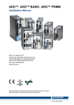
AKD® Central Power Supply
Installation Manual
Edition: A, November 2013
Valid for AKD-C, Hardware Revision A
Part Number 903-200019-00
Original Document
Keep all manuals as a product component during the life span of the product.
Pass all manuals to future users and owners of the product.
Record of Document Revisions
Revision
A, 11/2013
Remarks
First edition
Hardware Revision (HR)
AKD-N
A
AKD-C
A
Firmware
from 1.10
WorkBench
from 1.10
Remarks
AKD-C Start revision
Trademarks
l
l
l
l
l
AKD is a registered trademark of Kollmorgen Corporation
EnDat is a registered trademark of Dr. Johannes Heidenhain GmbH
EtherCAT is a registered trademark and patented technology, licensed by Beckhoff Automation GmbH
HIPERFACE is a registered trademark of Max Stegmann GmbH
Windows is a registered trademark of Microsoft Corporation
Current patents
l
l
l
l
l
US Patent 5,162,798 (used in control card R/D)
US Patent 5,646,496 (used in control card R/D and 1 Vp-p feedback interface)
US Patent 6,118,241 (used in control card simple dynamic braking)
US Patent 8,154,228 (Dynamic Braking For Electric Motors)
US Patent 8,214,063 (Auto-tune of a Control System Based on Frequency Response)
Technical changes which improve the performance of the device may be made without prior notice!
Printed in Germany
This document is the intellectual property of Kollmorgen. All rights reserved. No part of this work may be reproduced in any form (by photocopying, microfilm or any other method) or stored, processed, copied or distributed
by electronic means without the written permission of Kollmorgen.
2
Kollmorgen | November 2013
AKD-C Installation | Table of Contents
1 Table of Contents
1 Table of Contents
2 General
3
7
2.1 About this Manual
8
2.2 Using the PDF Format
8
2.3 Notes for the Printed Edition (paper version)
8
2.4 Symbols Used
9
2.5 Abbreviations Used
10
2.6 Standards Used
11
12
3 Safety
3.1 You should pay attention to this
13
3.2 Use as Directed
15
3.3 Prohibited Use
15
3.4 Handling
16
3.4.1 Packaging
16
3.4.2 Transport
16
3.4.3 Storage
16
3.4.4 Maintenance and cleaning
16
3.4.5 Uninstalling
17
3.4.6 Repair and disposal
17
4 Approvals
18
4.1 Conformance with UL/cUL
19
4.2 Conformance with EC Low Voltage and EMC Directives
19
4.3 Conformance with EC Machinery Directive, Functional Safety
19
20
5 Package
5.1 Package Supplied
21
5.2 Nameplate
21
5.3 Part Number Scheme
22
6 Technical description and data
23
6.1 The AKD-C Central Power Supply
24
6.2 Mechanical Data
25
6.3 Electrical Data
25
6.4 Fusing
26
6.4.1 External power supply fusing
26
6.4.2 External regen resistor fusing
26
6.5 Ambient Conditions, Ventilation, and Mounting Position
26
6.6 Grounding System
27
6.7 Signal Inputs/Outputs
27
6.8 Connectors
28
6.9 Recommended Tightening Torques
28
6.10 Cable Requirements
28
6.11 Cable Length Definition
29
6.12 Dynamic Braking
30
6.13 Regen circuit
30
Kollmorgen | November 2013
3
AKD-C Installation | Table of Contents
6.13.1 Functional description
30
6.13.2 Technical data
30
6.14 Switch-On and Switch-Off Behavior
6.14.1 Switch-on behavior in standard operation
31
6.14.2 Switch-off process, standard operation
32
6.15 Global Safe Torque Off (STO)
33
6.15.1 General information
33
6.15.2 Safety characteristic data
34
6.15.3 Use as directed
34
6.15.4 Prohibited use
34
6.15.5 STO Safety instructions
35
6.15.6 Enclosure, wiring
35
6.15.7 Technical data and connection
36
6.15.8 Functional description
37
6.15.8.1 Signal diagram (sequence)
38
6.15.8.2 Functional test
38
6.15.8.3 Control circuit (example)
38
6.15.8.4 Mains supply circuit (example)
38
6.16 Shock-hazard Protection
39
6.16.1 Leakage current
39
6.16.2 Residual current protective device (RCD)
39
6.16.3 Isolating transformers
39
6.17 LED Display
7 Mechanical Installation
39
40
7.1 Important Notes
41
7.2 Mechanical Drawings
42
7.2.1 Dimensions
42
7.3 Mounting Example
43
8 Electrical Installation
44
8.1 Important Notes
45
8.2 Guide to Electrical Installation
45
8.3 EMI Noise Reduction
46
8.3.1 Recommendations for EMI noise reduction
46
8.3.2 Shielding connection to the drive
47
8.3.2.1 Shield connection clamps for X12, X13, X14, X15, X16
47
8.3.2.2 Ethernet connectors X10, X11, X18
47
8.3.2.3 DC power connector X20A, X21A (cable CCNCN1)
47
8.3.2.4 Local fieldbus connectors X20B, X21B (cable CCNCN1)
47
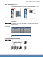
8.4 System Topology of a Decentralized Servo System
4
31
48
8.4.1 System limits
48
8.4.2 Example for one AKD-C
48
8.4.3 Example for several AKD-C
49
8.5 Wiring
50
8.6 Connection Overview
51
8.6.1 Connector assignment
51
8.6.2 Connection diagram
52
Kollmorgen | November 2013
AKD-C Installation | Table of Contents
8.7 Electrical Supply Connection
53
8.7.1 Connection to various mains supply networks
53
8.7.2 Mains supply connection (X12)
54
8.7.2.1 Three phase connection
54
8.7.3 24 VDC supply voltage (X13)
55
8.8 DC Bus link (X14)
56
8.8.1 Regen resistor (X14)
57
8.8.1.1 Internal regen resistor
57
8.8.1.2 External regen resistor
57
8.8.2 Capacitor Modules (X14)
58
8.8.2.1 Technical Data
58
8.8.2.2 Example installation with KCM-S and KCM-E
59
8.8.2.3 Example installation with KCM-P and KCM-E
60
8.8.2.4 Discharging KCM modules
61
8.9 Drive String Connection
62
8.9.1 String assignment
62
8.9.2 DC power (X20A, X21A)
63
8.9.3 Local Fieldbus (X20B, X21B)
63
8.10 I/O Connection
64
8.10.1 I/O connectors X15 and X16
64
8.10.2 Digital Input (ENABLE, X15)
65
8.10.3 Digital Output (X15)
66
8.10.4 FAULT relay contacts
67
8.10.5 STO signals (X16)
67
8.11 Motion Bus Interface (X10/X11)
68
8.11.1 Pinout
68
8.11.2 Bus Protocols
68
8.11.3 Network configuration
68
8.11.4 EtherCAT
68
8.12 Service Interface (X18)
69
8.12.1 Pinout
69
8.12.2 Service Bus Protocols
69
8.12.3 Possible Network Configurations
69
8.13 Pushbutton (B1)
70
8.14 Rotary Switches (S1), Setting IP address
71
9 Setup
72
9.1 Important Notes
73
9.2 Setup software WorkBench
74
9.2.1 Use as directed
74
9.2.2 Software description
75
9.2.3 Hardware requirements
75
9.2.4 Operating systems
75
9.2.5 Installation under Windows 2000/XP/VISTA/7
76
9.3 Initial System Test
77
9.3.1 Unpacking, mounting, and wiring
77
9.3.2 Set IP address
77
Kollmorgen | November 2013
5
AKD-C Installation | Table of Contents
9.3.3 Confirm connections
77
9.3.4 Install and start WorkBench
78
9.3.5 Enable the drive using the setup wizard
78
9.4 Fault and Warning Messages
79
9.5 Troubleshooting the AKD-C
81
10 Index
6
Kollmorgen | November 2013
83
AKD-C Installation | 2 General
2 General
2.1 About this Manual
8
2.2 Using the PDF Format
8
2.3 Notes for the Printed Edition (paper version)
8
2.4 Symbols Used
9
2.5 Abbreviations Used
10
2.6 Standards Used
11
Kollmorgen | November 2013
7
AKD-C Installation | 2 General
2.1 About this Manual
This manual, AKD-C Installation Manual ("Instructions Manual" according to EC Machinery
Directive 2006/42/EC), describes the AKD-C (Central Power Supply) and includes information needed to safely install decentral drive system with an AKD-C and several AKD-N
drives. A digital version of this manual (pdf format) is available on the DVD included with your
device. Manual updates can be downloaded from the Kollmorgen website (www.kollmorgen.com).
Additional documents include the following:
l
l
l
l
l
Decentralized System Projecting Guide: describes how to build a decentralized drive system with AKD-C and AKD-N. It provides tips for system topology, cooling, and maximizing the system performance.
AKD-N Installation Manual: describes the AKD-N series of drives for Kollmorgen decentralized drive system and includes information needed for safe assembling and installation of the drives.
Decentralized System User Guide: describes how to use your drive in common applications. It also provides tips for maximizing your system performance. The User Guide
includes the Parameter and Command Reference Guide which provides documentation
for the parameters and commands used to program the AKD-N.
EtherCAT Communication: describes how to use your system in EtherCAT applications.
Accessories Manual.It provides documentation for accessories like cables and regen
resistors used with AKD-C and AKD-N. Regional variants of this manual exist.
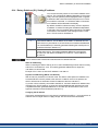
2.2 Using the PDF Format
This document includes several features for ease of navigation
Cross References
Table of contents and index include active cross references.
Table of contents and index
Lines are active cross references. Click on the line
and the appropriate page is accessed.
Page/chapter numbers in the text
Page/chapter numbers with cross references are
active links.
2.3 Notes for the Printed Edition (paper version)
A printed version of the manual is enclosed with each product. For environmental reasons,
the document was reduced in size and printed on DIN A5.
Should you experience difficulties reading the font size of the
scaled-down printed version, you can print and use the PDF version in DIN A4 format 1:1. You can find the PDF version on the
DVD accompanying the product and on the Kollmorgen website.
8
Kollmorgen | November 2013
AKD-C Installation | 2 General
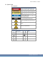
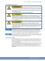
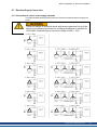
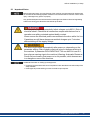
2.4 Symbols Used
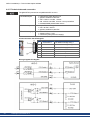
Warning Symbols
Symbol
Indication
Indicates a hazardous situation which, if not
avoided, will result in death or serious injury.
Indicates a hazardous situation which, if not
avoided, could result in death or serious injury.
Indicates a hazardous situation which, if not
avoided, could result in minor or moderate
injury.
This is not a safety symbol.
Indicates situations which, if not avoided, could
result in property damage.
This is not a safety symbol.
This symbol indicates important notes.
Warning of a danger (general). The type of
danger is specified by the text next to the symbol.
Warning of danger from electricity and its
effects.
Warning of suspended loads.
Drawing symbols
Symbol
Description
Signal ground
Symbol
Description
Diode
Chassis ground
Relay
Protective earth
Relay switch off delayed
Resistor
Normally open contact
Fuse
Normally closed contact
Kollmorgen | November 2013
9
AKD-C Installation | 2 General
2.5 Abbreviations Used
10
Abbreviation
CE
Meaning
Communité Européenne
COM
Serial interface for a personal computer
DCOM
Communication line for digital inputs
Disk
Magnetic storage (diskette, hard disk)
EEPROM
Electrically erasable programmable memory
EMC
Electromagnetic compatibility
KAS
Kollmorgen Automation Suite
KAS IDE
Setup software (Kollmorgen Automation Suite Integrated Development Environment) used for AKD PDMM drives
LED
Light-emitting diode
LSB
Low significant byte (or bit)
MSB
Main significant byte (or bit)
NI
Zero pulse
OSSD
Output signals Switching Device
PC
Personal computer
PE
Protective earth
PELV
Protective extra low voltage
PLC
Programmable logic control
PWM
Pulse-width modulation
RAM
Random access memory (volatile memory)
RBrake/RB
Regen resistor (also called a brake resistor)
RBext
External regen resistor
RBint
Internal regen resistor
RCD
Residual current device
RES
Resolver
ROD
Incremental encoder (A quad B)
SELV
Safety Extra Low Voltage
STO
Safe torque off
VAC
Volts, alternating current
VDC
Volts, direct current
Kollmorgen | November 2013
AKD-C Installation | 2 General
2.6 Standards Used
Standard
ISO 4762
Content
Hexagon socket head cap screws
ISO 11898
Road vehicles — Controller area network (CAN)
ISO 12100
Safety of machinery: Basic concepts, general principles for design
ISO 13849
Safety of machinery: Safety-related parts of control systems
IEC 60085
Electrical insulation - Thermal evaluation and designation Maintenance
IEC 60204
Safety of Machinery: Electrical equipment of machinery
IEC 60364
Low-voltage electrical installations
IEC 60439
Low-Voltage Switchgear and Controlgear Assemblies
IEC 60529
International protection rating (IP code)
IEC 60664
Insulation coordination for equipment within low-voltage systems
IEC 60721
Classification of environmental conditions
IEC 61000
Electromagnetic compatibility (EMC)
IEC 61131
Programmable controllers
IEC 61491
Electrical equipment of industrial machines – Serial data link for real-time
communications between controls and drives.
IEC 61508
Functional safety of electrical/electronic/programmable electronic safetyrelated systems
IEC 61800
Adjustable speed electrical power drive systems
IEC 62061
Functional safety of electrical/electronic/programmable electronic safetyrelated systems
IEC 82079
Preparation of instructions for use - Structuring, content and presentation
ANSI Z535
Product safety (symbols, colors, information)
UL 840
UL Standard for Safety for Insulation Coordination Including Clearances and
Creepage Distances for Electrical Equipment
UL 508C
UL Standard for Safety Power Conversion Equipment
ANSI - American National Standard Institute, Inc.
IEC - International Electrotechnical Commission
ISO - International Organization for Standardization
UL - Underwriters Laboratories
Kollmorgen | November 2013
11
AKD-C Installation | 3 Safety
3 Safety
12
3.1 You should pay attention to this
13
3.2 Use as Directed
15
3.3 Prohibited Use
15
3.4 Handling
16
Kollmorgen | November 2013
AKD-C Installation | 3 Safety
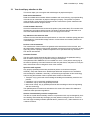
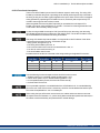
3.1 You should pay attention to this
This section helps you to recognize and avoid dangers to people and objects.
Read the documentation!
Read the available documentation before installation and commissioning. Improper handling
of the device can cause harm to people or damage to property. The operator of systems
using the AKD-C must require that all personnel who work with the system read and understand the manual before using the device.
Check Hardware Revision!
Check the Hardware Revision Number of the product (see product label). This number is the
link between your product and the manual. The product Hardware Revision Number must
match the Hardware Revision Number on the cover page of the manual.
Pay attention to the technical data!
Adhere to the technical data and the specifications on connection conditions (rating plate and
documentation). If permissible voltage values or current values are exceeded, the devices
can be damaged.
Perform a risk assessment!
The manufacturer of the machine must generate a risk assessment for the machine, and
take appropriate measures to ensure that unforeseen movements cannot cause injury or damage to any person or property. Additional requirements on specialist staff may also result
from the risk assessment.
Automatic Restart!
The drive might restart automatically after power on, depending on the parameter setting.
Risk of death or serious injury for humans working in the machine.
If the parameter DRV.ENDEFAULT for one AKD-N is set to 1, then place a warning sign to
the machine (Warning: Automatic Restart at Power On) and ensure, that power on is not possible, while humans are in a dangerous zone of the machine.
Specialist staff required!
Only properly qualified personnel are permitted to perform such tasks as transport,
assembly, setup and maintenance. Qualified specialist staff are persons who are familiar
with the transport, installation, assembly, commissioning and operation of drive technology
and who bring their relevant minimum qualifications to bear on their duties:
l
l
l
l
Transport: only by personnel with knowledge of handling electrostatically sensitive components.
Unpacking: only by electrically qualified personnel.
Installation: only by electrically qualified personnel.
Basic tests / Setup: only by qualified personnel with knowledge of electrical engineering
and drive technology
The qualified personnel must know and observe ISO 12100 / IEC 60364 / IEC 60664 and
national accident prevention regulations.
Observe electrostatically sensitive components!
The devices contain electrostatically sensitive components which may be damaged by incorrect handling. Electrostatically discharge your body before touching the device. Avoid contact with highly insulating materials (artificial fabrics, plastic film etc.). Place the device on a
conductive surface.
Kollmorgen | November 2013
13
AKD-C Installation | 3 Safety
Earthing!
It is vital that you ensure that the device is safely earthed to the PE (protective earth) busbar
in the switch cabinet. Risk of electric shock. Without low-resistance earthing no personal protection can be guaranteed.
Leakage Current!
Since the leakage current to PE is more than 3.5 mA, in compliance with IEC61800-5-1 the
PE connection must either be doubled or a connecting cable with a cross-section >10 mm²
must be used. Deviating measures according to regional standards might be possible.
Residual current protective or monitoring devices!
AKD-C with AKD-N can cause a d.c. current in the protective earthing conductor. Where a
residual current-operated protective (RCD) or monitoring (RCM) device is used for protection
in case of direct or indirect contact, only an RCD or RCM of Type B is allowed on the supply
side of AKD-C.
High voltages!
The equipment produces high electric voltages up to 900V. Do not open or touch the equipment during operation. Keep all covers closed.
During operation, AKD-C may have uncovered live sections, according to their level of enclosure protection. Wait at least seven minutes after disconnecting the product from the main
supply power before touching potentially live sections of the equipment (such as contacts) or
removing any connections.
Capacitors can have dangerous voltages present up to seven minutes after switching off the
supply power. Always measure the voltage in the DC bus link at connector X14 and wait until
the voltage is below 60 V before handling components.
Never undo any electrical connections to the AKD-C while it is live. There is a danger of electrical arcing with damage to contacts and personal injury.
Never modify the product!
It is not allowed to modify the product without permission by the manufacturer. Opening the
housing causes loss of warranty.
14
Kollmorgen | November 2013
AKD-C Installation | 3 Safety
3.2 Use as Directed
AKD-C are components that are built into electrical plants or machines and can only be operated as integral components of these plants or machines. The manufacturer of the machine
must generate a risk assessment for the machine.
Kollmorgen Decentral drive system
AKD-C series power supply must only be operated in a motion system with components
from Kollmorgen. Required additional Kollmorgen components are the "near servo drives"
AKD-N, CCNCx series of hybrid cables, motor power and feedback cables, servomotors.
Assembling
AKD-C devices must only be operated in environments suitable for the ambient conditions
defined on ➜ p. 26. Observe the information given in the Decentralized System Projecting
Guide.
Wiring
Use only Kollmorgen CCx/ WCx/HCx series of hybrid cables for connecting AKD-N and
AKD-C devices.
Power supply
AKD-C must be powered from a 3 phase industrial supply network
(not more than 200 kA symmetrical rated current at 400 V and 480 V).
Auxiliary voltage supply, Standby power
Standby power for the drive strings must only be used for supplying the AKD-N electronics.
24 VDC supply unit must accord to PELV/SELV (EN 60204-1) requirements.
Safe torque off
The Safe Torque Off (STO) functionality is in the certification process. As long as the function is not safety certified, it should not be used as safety function according to ISO 13849.
3.3 Prohibited Use
Other use than that described in chapter “Use as directed” is not intended and can lead to personnel injuries and equipment damage.
The device may not be used
l
l
l
l
with a machine that does not comply with appropriate national directives or standards,
for driving elevators,
in applications with continuous, operational short circuits to the external regen resistor
contacts.
in applications with any short circuits to the DC-Bus link contacts.
The use of the device in the following environments is also prohibited:
l
l
l
potentially explosive areas
environments with corrosive and/or electrically conductive acids, alkaline solutions, oils,
vapors, dusts
ships or offshore applications
Wiring the system with hybrid cables from other manufacturers than Kollmorgen is not
allowed. Changing Kollmorgen cables or connectors is not allowed.
Kollmorgen | November 2013
15
AKD-C Installation | 3 Safety
3.4 Handling
3.4.1 Packaging
The AKD-C packaging consists of recyclable cardboard with inserts and a label on the outside of the box.
Model
AKD-C01007
Package Dimensions
(mm) HxWxL
125 x 410 x 295
Total Weight
(kg)
5
3.4.2 Transport
Transport the AKD-C in accordance with IEC 61800-2 as follows:
l
l
l
l
l
Transport only by qualified personnel in the manufacturer’s original recyclable packaging.
Avoid shocks while transporting.
Store at or below maximum stacking height of 8 cartons
Transport only within specified temperature ranges: -25 to +70 °C, max. rate of change 20
K/hour, class 2K3.
Transport only within specified humidity: maximum 95% relative humidity, no condensation, class 2K3.
The devices contain electrostatically sensitive components that can be damaged by incorrect handling. Electrostatically discharge yourself before touching the device. Avoid contact
with highly insulating materials, such as artificial fabrics and plastic films. Place the device
on a conductive surface.
If the packaging is damaged, check the unit for visible damage. Inform the shipper and the
manufacturer of any damage to the package or product.
3.4.3 Storage
Store the AKD-C in accordance with IEC 61800-2 as follows:
l
l
l
l
Store only in the manufacturer’s original recyclable packaging.
Store at or below maximum stacking height of 8 cartons
Store only within specified temperature ranges: -25 to +55 °C, max.rate of change 20
K/hour, class 1K4.
Storage only within specified humidity: 5 to 95% relative humidity, no condensation, class
1K3.
3.4.4 Maintenance and cleaning
The device does not require maintenance. Opening the device voids the warranty.
The inside of the unit can only be cleaned by the manufacturer. To clean the device exterior:
l
l
Casing: Clean with isopropanol or similar cleaning solution.
Protective grill on fan: Clean with a dry brush.
Do not immerse or spray the device .
16
Kollmorgen | November 2013
AKD-C Installation | 3 Safety
3.4.5 Uninstalling
If a drive must be uninstalled (such as for replacement), remove the device as follows:
1. Switch off the main switch of the switchgear cabinet and the fuses that supply the system.
Contacts can still have dangerous voltage present up to seven minutes
after switching off mains voltage. Risk of electrical shock! Wait at least
seven minutes after disconnecting the AKD-C from the main supply
power before touching potentially live sections of the equipment (e.g. contacts) or undoing any connections. Always measure the voltage in the DC
bus link at connector X14 and wait until the voltage is below 60 V before
handling components.
2. Remove the connectors. Disconnect the potential earth connection last.
3. Check temperature.
4. Uninstall. Remove the AKD-C.
3.4.6 Repair and disposal
Only the manufacturer can repair the AKD-C. Opening the device voids the warranty. Uninstall the device as described in "Uninstalling" (➜ p. 17), then send the device in the original
packaging to the manufacturer (see table below). Transport costs are the responsibility of the
senders.
In accordance with the WEEE-2002/96/EC-Guidelines and similar, the manufacturer
accepts returns of old devices and accessories for professional disposal. Transport costs
are the responsibility of the sender. Send the devices to the manufacturer addresses shown
in the table below.
USA
Kollmorgen
201 West Rock Road
Radford, VA 24141
Europe
KOLLMORGEN Europe GmbH
Pempelfurtstr. 1
D-40880 Ratingen
Kollmorgen | November 2013
17
AKD-C Installation | 4 Approvals
4 Approvals
18
4.1 Conformance with UL/cUL
19
4.2 Conformance with EC Low Voltage and EMC Directives
19
4.3 Conformance with EC Machinery Directive, Functional Safety
19
Kollmorgen | November 2013
AKD-C Installation | 4 Approvals
4.1 Conformance with UL/cUL
Planned.
4.2 Conformance with EC Low Voltage and EMC Directives
CE Declarations of Conformity can be found on the Kollmorgen website or on page "Approvals" in the Kollmorgen Product WIKI.
Conformance with the EC EMC Directive 2004/108/EC and the Low Voltage Directive
2006/95/EC is mandatory for the supply of drives within the European Community.
The devices have been tested by an authorized testing laboratory in a defined configuration,
using the system components that are described in this documentation. Any divergence from
the configuration and installation described in this documentation means that the user will be
responsible for carrying out new measurements to ensure conformance with regulatory
requirements.
Kollmorgen declares the conformity of the product series AKD-C01007 with the following
directives:
EC Directive 2006/95/EC, low voltage
Used harmonized standard EN61800-5-1 (2007)
EC Directive 2004/108/EC, electromagnetic compatibility
Used harmonized standard EN 61800-3 (2004)
The AKD-C01007 meet the noise immunity requirements to the 2nd environmental category
(industrial environment). For noise emission theAKD-C01007 meet the requirement to a product of the Category C2.
These devices can cause high-frequency interferences in non industrial environments and
may require measures for interference suppression (such as additional external EMC filters).
4.3 Conformance with EC Machinery Directive, Functional Safety
Conformance with the EC Machinery Directive 2006/42/EC is mandatory for the supply of
safety components within the European Community.
Safe Torque Off (STO) string type
Certification in process.
Safe Torque Off (STO) single drive type
See AKD-N Installation Manual for detailed information. Certification in process.
Kollmorgen | November 2013
19
AKD-C Installation | 5 Package
5 Package
20
5.1 Package Supplied
21
5.2 Nameplate
21
5.3 Part Number Scheme
22
Kollmorgen | November 2013
AKD-C Installation | 5 Package
5.1 Package Supplied
When a device from the AKD-C series is ordered,, the following items are included in the
package:
l
l
l
l
l
AKD-C
Printed copy of AKD-C Installation Manual
DVD containing the setup software, WorkBench, and all product documentation in digital
format.
Mating connectors X12, X13, X14, X15, X16
Two connector covers M23
The M23 connector covers are required for protecting X2 of the last AKD-N in the strings.
Accessories Sold Separately
Accessories must be ordered separately if required; refer to your regional accessories manual:
l
l
l
l
Hybrid cables for connection to first AKD-N
External regen resistor
EtherCAT cable to the network
Power cable, control wires
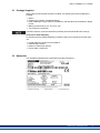
5.2 Nameplate
The nameplate depicted below is attached to the side of the device.
Kollmorgen | November 2013
21
AKD-C Installation | 5 Package
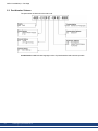
5.3 Part Number Scheme
The part number is identical to the order code.
Customization code includes language version of printed material and customer specials.
22
Kollmorgen | November 2013
AKD-C Installation | 6 Technical description and data
6 Technical description and data
6.1 The AKD-C Central Power Supply
24
6.2 Mechanical Data
25
6.3 Electrical Data
25
6.4 Fusing
26
6.5 Ambient Conditions, Ventilation, and Mounting Position
26
6.6 Grounding System
27
6.7 Signal Inputs/Outputs
27
6.8 Connectors
28
6.9 Recommended Tightening Torques
28
6.10 Cable Requirements
28
6.11 Cable Length Definition
29
6.12 Dynamic Braking
30
6.13 Regen circuit
30
6.14 Switch-On and Switch-Off Behavior
31
6.15 Global Safe Torque Off (STO)
33
6.16 Shock-hazard Protection
39
6.17 LED Display
39
Kollmorgen | November 2013
23
AKD-C Installation | 6 Technical description and data
6.1 The AKD-C Central Power Supply
Available AKD versions
Variant
Description
AKD-C01007-CBEC Central Power supply without
extension.
Power
10 kW
Connectivity
EtherCAT, Ethernet/IP
Standard features
l
l
l
l
l
l
Supply voltage range 400 V to 480 V ±10%.
Mains EMC filter and 24 V EMC filter integrated.
EtherCAT bus onboard.
TCP/IP service channel 100 Mbit/s onboard.
Safe Torque Off (STO) according to IEC 61508 SIL 2 onboard.
Supports up to 16 AKD-N drives.
Power section
l
l
l
l
l
l
l
l
l
Three phase supply, maximum voltage range 360 to 528 V, 47 to 65 Hz.
B6 bridge rectifier, integral soft-start circuit.
Fusing to be provided by the user.
Shielding star point close to the device.
DC power split to two connectors (strings) for up to 16 drives.
DC power voltage range 565 to 680 VDC, DC bus output current max 17 A.
Standby DC power voltage 55 VDC ±10% (generated from 24 VDC voltage supply)
Regen circuit for all connected AKD-N.
Built-in regen resistor, external regen resistor or capacitor module if required.
Integrated safety
l
l
l
l
Appropriate insulation/creepage distances and electrical isolation for safe electrical separation, per IEC 61800-5-1, between the power input/DC bus connections and the signal
electronics.
Soft-start, overvoltage detection, short-circuit protection, phase-failure monitoring.
Temperature monitoring.
SIL 2 safe torque off in accordance with IEC 61508, ➜ p. 33.
Supply voltage 24V DC (electronic supply and standby voltage)
l
From an external, safety approved 24 V ±10% power supply, minimum 480 W.
Operation and parameter setting
l
Using the setup software WorkBench for setup via TCP/IP.
Inputs/Outputs
l
l
l
l
l
l
l
24
1 programmable digital output (➜ p. 66)
1 fault relay output (➜ p. 67)
1 Enable input (➜ p. 65)
2 STO inputs (one per string) (➜ p. 33)
2 STO status outputs (one per string) (➜ p. 33)
Service Interface (➜ p. 69)
EtherCAT Interface (➜ p. 68)
Kollmorgen | November 2013
AKD-C Installation | 6 Technical description and data
6.2 Mechanical Data
Mechanical data
Weight
Units
kg
AKD-C01007-x
3.8
Height front
mm
290
Height back
mm
329
Width
mm
80
Depth, without connectors
mm
198
Depth, with connectors
mm
231
6.3 Electrical Data
Electrical data
Rated supply voltage
Units
V~
Value
3 x 400 V to 3 x 480 V, ±10%
Hz
50 Hz to 60 Hz, ±10%
at 3x400 V
kVA
9.2
at 3x480 V
kVA
11
Rated input current at 3x400/480 V
A
14
Permitted switch on/off frequency
1/h
30
A
5
Rated DC bus link voltage
(Bus Turn on Delay 3ph 1 sec)
V=
565 to 680
Standby DC power voltage
V=
55 ±10%
Continuous total output current
A=
17
Peak total output current (for 1 s, ± 3%)
A=
34
at 3x400 V
kVA
9.2
at 3x480 V
kVA
11
at 3x400 V
kVA
18.4
at 3x480 V
kVA
22
—
➜ p. 30
No AKD-N (min)
W
8.6
16 AKD-N (max)
Rated supply input frequency
Rated input power
Max. inrush current
Continuous output power
Peak output power (for 1 s)
Technical data for regen circuit
Thermal dissipation at 24V standby
W
40
Thermal dissipation at rated current (without
regen power)
W
125
Noise emission (low speed / high speed fan)
dB(A)
40 / 60
Aux. voltage supply (PELV)
V=
24 V (±10%, check voltage
drop)
Aux. voltage supply current
A=
14
Aux. voltage inrush current
A=
16
-
IP20
Protection class
Kollmorgen | November 2013
25
AKD-C Installation | 6 Technical description and data
6.4 Fusing
US fuses: Class RK5 or CC or J, 600 VAC 200 kA, time-delay. The fuse must be UL and
CSA listed, UL recognized is not sufficient.
EU fuses: types gRL or gG, 400 V/500 V, time-delay
Fuse holders: Combined with the standard fuse blocks, finger safe fuse holders must be
used according to IEC 60529.
Examples:
Bussmann: CH Series Modular Fuse Holders, fuse size 0 to 30A class J, 3 poles: CH30J3
Ferraz: Ultrasafe Fuse holders, fuse size 0 to 30A class J, 3 poles: US3J3I
6.4.1 External power supply fusing
External AC power
supply fusing
External 24 VDC
supply fusing
Ampere rating UL Region
20A (Time-Delay) in process
CE Region
example:
Siba
type gRL/gG, D02, 20A
15A (Time-Delay) in process
example:
Siba
type in process
6.4.2 External regen resistor fusing
AKD-C01007
Ampere rating
25A
UL Region
in process
CE Region
example:
Siba
type in process
6.5 Ambient Conditions, Ventilation, and Mounting Position
Storage
➜ p. 16
Transport
➜ p. 16
Ambient temperature
in operation
0 to +40 °C under rated conditions
+40 to +55 °C with continuous current derating 4 % per Kelvin
Humidity in operation
Relative humidity 5 to 85%, no condensation, class 3K3
Site altitude
Up to 1000 meters above mean sea level without restriction
1,000 to 2,000 meters above mean sea level with power derating 1.5%/100 m
Pollution level
Pollution level 2 as per IEC 60664-1
Vibrations
Class 3M1 according to IEC 60721-3-3
Environmental area
Cabinet IP 54 according to IEC 60529
Mounting position
Vertical
Ventilation
Built-in fan
The device shuts down in case of excessively high temperature in the control cabinet. Make sure sufficient forced
ventilation is supplied within the control cabinet.
26
Kollmorgen | November 2013
AKD-C Installation | 6 Technical description and data
6.6 Grounding System
There are several ground networks in the drive:
DCOM
common line for digital inputs on I/O connector X15
GND
24 V supply
STO-GND
STO input
0V
internal digital ground, service channel
6.7 Signal Inputs/Outputs
Interface
Enable input
Digital output
Electrical Data
l as per IEC61131-2 type 1
l ON: 15 VDC to 30 VDC, 2 mA to 15 mA
l OFF: -3 VDC to 5 VDC, < 1 mA
l update rate 250 µs
l galvanic isolation for 250 VDC
l
l
l
l
Relay output
l
l
l
l
STO-Enable inputs
l
l
l
STO-Status outputs
l
l
l
as per IEC61131-2 type 1
max. 30 VDC, 100 mA
short circuit proof
galvanic isolation for 250 VDC
max. 30 VDC, 1A
max. 42 VAC, 1 A
time open/close 10ms
isolation 400 VDC contact/coil
ON: 18 VDC to 30 VDC, 210 mA +10 mA per AKD-N
OFF: 0 VDC to 12 VDC, < 50 mA
galvanic isolation for 250 VDC
as per IEC61131-2 type 1
max. 30 VDC, 100 mA
galvanic isolation for 250 VDC
Kollmorgen | November 2013
27
AKD-C Installation | 6 Technical description and data
6.8 Connectors
Given voltage and current data are the lowest values allowed by UL and CE. Connector
Type
Max. Cross
Section1
0,5 mm², 21 awg
Motion Bus X10, X11 RJ45
Current2 Voltage3
1A
<100 V
Power X12
Terminal Connector, 4 poles 10 mm², 8 awg
30 A
600 V
Aux. voltage X13
Terminal Connector, 2 poles 2.5 mm², 12 awg
16 A
250 V
DC bus, Regen X14 Terminal Connector, 4 poles 10 mm², 8 awg
30 A
600 V
Control signals X15
Terminal Connector, 6 poles 1 mm², 18 awg
12 A
250 V
STO signals X16
Terminal Connector, 6 poles 1 mm², 18 awg
12 A
250 V
Service Port X18
RJ45
1A
<100 V
DC Power X20A,
X21A
Terminal Connector, 3 poles 10 mm², 8 awg
30 A
600 V
0.5 A
30 V
0,5 mm², 21 awg
Local Fieldbus In/Out Mini I/O connector, 8 poles
X20B, X21B
0.34 mm², 22 awg
1single-line connection
2single-line connection with recommended conductor cross section (➜ p. 28)
3rated voltage with pollution level 2
6.9 Recommended Tightening Torques
Connector
X13, X15, X16
Tightening Torque/Nm
0.2 to 0.25
X12, X14, X20A, X21A
0.7 to 0.8
PE bolt
1.7
See "Conformance with UL/cUL" (➜ p. 19) for in-lbs values.
6.10 Cable Requirements
The table below describes the recommended interface cross sections and cable requirements in accordance with IEC 60204. For information on the chemical, mechanical, and electrical characteristics of the cables please refer to the accessories manual or contact
customer support.
Use Kollmorgen hybrid, motor, and feedback cables only. You will loss system warranty, if
you use hybrid, motor or feedback cables from a manufacturer other than Kollmorgen.
Hybrid cable from Cable type* Hybrid cable to
AKD-C X20A/X20B CCNCN1-025 AKD-N X1, hybrid
String 1
Cross section
3 x 2.5 mm²
4 x 0.25 mm²
AKD-C X21A/X21B
String 2
3 x 2.5 mm²
4 x 0.25 mm²
CCNCN1-025 AKD-N X1, hybrid
* Followed by length coding. Contact your Kollmorgen sales representative.
28
Interface
X12, AC connection
Cross Section Cable Requirements
4.0 mm² (12 awg) 600 V,minimum 75°C
X13, +24 V/GND, max 30 m
2.5 mm² (14 awg) single line
X14, DC bus link, regen resistor
4.0 mm² (12 awg) 1000 V, minimum 75°C, shielded for
lengths >0.20 m
X15, Digital I/Os, max. 30 m
0.5 mm² (21 awg) single line
X16, STO Signals, max. 30 m
0.5 mm² (21 awg) single line
Kollmorgen | November 2013
AKD-C Installation | 6 Technical description and data
6.11 Cable Length Definition
AKD-C offers two separate strings to connect up to 8 AKD-N to each of them. Maximum
total cable length for each string is 100 m. For system topology information refer to ➜ p. 48
Cable
Type
CCNCN1
Cable usage
AKD-C to AKD-N, hybrid
Available
Length (m)
3, 6, 12, 24, 36
Max.
Length (m)
40
Ethernet Cable
AKD-C to AKD-C
on request
100
Ethernet Cable
AKD-C to Personal Computer or Switch on request
100
Kollmorgen | November 2013
29
AKD-C Installation | 6 Technical description and data
6.12 Dynamic Braking
Dynamic braking is a method to slow down a servo system by dissipating the mechanical
energy driven by the motor back EMF. The AKD-N drives have a built in advanced dynamic
braking mode which operates fully in hardware. When activated, the drive shorts the motor
terminals in phase with the back EMF (q axis) but continues to operate the non-force producing current loop (d-axis) with 0 current. This forces all of the dynamic braking current to be
stopping current and insures the fastest stopping/amp of motor terminal current.
l
l
l
When current is not being limited, the mechanical energy is being dissipated in the motor
resistance.
When current is being limited, energy is returned to the AKD-C bus capacitors.
The drive also limits the maximum dynamic braking motor terminal current via the
DRV.DBILIMIT parameter to insure that the drive, motor, and customer load do not see
excessive currents/forces.
Whether and how the AKD uses dynamic braking depends on (DRV.DISMODE).
6.13 Regen circuit
When the amount of returned energyfrom the AKD-N builds the bus capacitor voltage up
enough, the AKD-C activates the regen circuit to start dumping the returned energy in the
regen resistor (also called regenerative or brake resistor). The AKD-C has an internal regen
resistor, an additional external one can be connected to X14.
External regen resistors are described in the regional Accessories Manual.
6.13.1 Functional description
When the amount of returned energy builds the bus capacitor voltage up enough, the AKD-C
activates the brake chopper to start dumping the returned energy in the regen resistor at the
AKD-C (internally or connected to terminal X14). 90% of the combined power of all the coupled drives is always available for peak and continuous power.
The drive that has the lowest switch-off threshold (resulting from tolerances) reports an overvoltage fault if the DC bus threshold is exceeded. The drive power stage is disabled and the
load coasts to a stop with the fault message “F501 Bus Over voltage" (➜ p. 79). The AKD-C
fault relay contact (terminals X15/5-6) is opened due to this fault.
6.13.2 Technical data
Observe the regeneration time (some minutes) after full load with peak regen power.
Rated data
Switch-on threshold of regen circuit (nominal)
Units
V
400 V
760
480 V
760
Overvoltage limit
V
840
840
Maximum regen duty cycle
%
15*
15*
Internal regen resistor
Ohm
33
33
Continuous power, internal resistor
W
100
100
Peak regen power, internal resistor (0.5s)
kW
17.5
17.5
Ohm
33
33
External regen resistor
Maximum continuous regen power, external resistor
kW
1.5
1.5
Peak regen power, external (1s)
kW
17.5
17.5
Absorption energy in capacitors (+/- 20%)
Ws
21
7
DC Bus Capacitance (nominal)
µF
585
585
* depends on connected regen resistor power
30
Kollmorgen | November 2013
AKD-C Installation | 6 Technical description and data
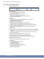
6.14 Switch-On and Switch-Off Behavior
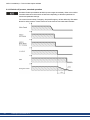
6.14.1 Switch-on behavior in standard operation
The diagram below illustrates the correct functional sequence for switching the System on.
Kollmorgen | November 2013
31
AKD-C Installation | 6 Technical description and data
6.14.2 Switch-off process, standard operation
Hardware Enable input disables all AKD-N power stages immediately. Refer to the AKD-N
Installation Manual for drive switch-off behaviour depending on different operational situations and parameter settings.
The control functions Stop, Emergency Stop and Emergency Off are defined by IEC 60204.
Notes for safety aspects of these functions can be found in ISO 13849 and IEC 62061.
32
Kollmorgen | November 2013
AKD-C Installation | 6 Technical description and data
6.15 Global Safe Torque Off (STO)
Certification of functional safety is in process.
6.15.1 General information
Connector X16 offers access to all STO (Safe Torque Off) relevant signals of the decentral
drive system powered by this AKD-C .
The global STO function uses the following devices: AKD-C, AKD-N without option "DS",
Kollmorgen hybrid connection cable.
There is one STO-Enable input and one STO-Status output for each DC Power string. STOEnable 1 does affect string 1 only. STO-Enable 2 does affect string 2 only.
The string STO input releases the power output stage of all AKD-N (without option DS) connected to the string as long as a 24 V signal is applied to this input. If the STO input goes
open-circuit, then power will no longer be supplied to the connected motors, and the drives
will lose all torque and coast to a stop.
In case of using an AKD-N with option "DS" (local STO input), the global STO signal will
have not influence to this specific drive. The local STO input on the AKD-N has no influence
to the global STO as well. The local STO functionality is described in the AKD-N installation
manual.
The STO safety implementation on the AKD is certified. The safety circuit implementation
used for the safety function "Safe Torque Off" in the drive is suited for SIL 2 according to IEC
61508-2 and PLd / CAT3 according to ISO 13849-1.
Application examples can be found in the Decentralized System Projecting Guide.
Kollmorgen | November 2013
33
AKD-C Installation | 6 Technical description and data
6.15.2 Safety characteristic data
The subsystems are described with the following characteristic data:
Device
STO
Operation
Mode
STO single
channel
ISO 13849-1
IEC 61508-2
PL d, CAT 3
SIL 2
PFH
[1/h]
0
TM [Years]
20
SFF
[%]
100
A very unlikely but possible event can happen, if within a very short time 2 not adjacent
IGBTs will have a short circuit. In such case a movement of maximum an angle of 120° (electrical) can happen. This effect can only happen if the drive is in the function STO.
In order to show the probability of such event, the following calculation can help. If the total
failure rate of the IGBT is 120 fit normally for such short circuit 60 fit will be valid (50:50
model). By such event 2 specific IGBTs have to fail at same time. The calculation shows a
probability of 1.5 * 10-15 per hour (without common cause failure). Even if the STO function
will be issued for a whole year, this event will only happen every 100 Billion years.
6.15.3 Use as directed
The STO function is exclusively intended to provide a functional safe torque off of the motion
system. To achieve this functional safety, the wiring of the safety circuits must meet the
safety requirements of IEC 60204, ISO 12100 and ISO 13849.
If the global STO function is in use, then the inputs STO-Enable 1/2 must be connected to the
exit of a security control or a safety relay, which at least meets the requirements of PLd, CAT
3 according to ISO 13849.
The 24 VDC supply unit for local STO supply must accord to PELV/SELV (EN 60204-1)
requirements.
6.15.4 Prohibited use
The STO function must not be used if the drive is to be made inactive for the following reasons:
l
l
l
l
34
Cleaning, maintenance and repair operations, long inoperative periods. In such cases, the
entire system should be disconnected from the supply and secured (main switch).
Emergency-Off situations. In an Emergency-Off situation, the main contactor is switched
off (by the Emergency-Off button).
Wiring the system with hybrid cables from other manufacturers than Kollmorgen is not
allowed.
Changing cables or connectors is not allowed.
Kollmorgen | November 2013
AKD-C Installation | 6 Technical description and data
6.15.5 STO Safety instructions
The drive cannot hold a vertical load when STO is active. Serious injury
could result when load is not properly blocked. Drives with a suspended
load must have an additional safe mechanical blocking (for instance, by a
motor-holding brake).
The drives have not to be used for driving elevators.
In case of a specific double fault within a very short time (see ➜ p. 34) a
single movement of maximum an angle of 120° (electrical) can happen.
This effect can only happen if the drive is in the function STO. Even if the
STO function will be issued for a whole year, this event will only happen
every 100 Billion years
The STO function does not provide an electrical separation from the
power output. There is a danger of electrical shock and personnel injury.
If access to the motor power terminals is necessary, the drive must be disconnected from mains supply considering the discharging time of the
intermediate circuit.
If the safety function STO is automatically activated by a control system, then make sure
that the output of the control is monitored for possible malfunction. The monitoring can be
used to prevent a faulty output from unintentionally activating the STO function. Since the
STO function is a single-channel system, erroneous engaging will not be recognized.
It is not possible to perform a controlled brake if the drive controlled STO-Enable is off. If controlled braking before the use of the STO function is necessary, the drive must be braked and
the input STO must be separated time-delayed from +24 V .
6.15.6 Enclosure, wiring
Observe the required ambient conditions as described in chapter "Ambient Conditions, Ventilation, and Mounting Position" (➜ p. 26). The AKD-C (IP 20) must be mounted in an IP54
cabinet to ensure pollution level 2 according to IEC 60664-1. The AKD-N can be used in an
environment that meet IP67.
If you are wiring leads that are outside the specified enclosure (IP54), the cables must be laid
durably (firmly), protected from outside damage (for example, by laying the cable in a duct),
placed in different sheathed cables, or protected individually by grounding connection.
Wiring remaining within the specified enclosure must meet the requirements of the standard
IEC 60204-1.
Kollmorgen | November 2013
35
AKD-C Installation | 6 Technical description and data
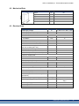
6.15.7 Technical data and connection
The global STO inputs are not compatible with IEC 61131-2.
STO-Enable inputs
l
l
l
l
l
STO-Status outputs
l
l
l
STO 24 VDC supply
l
l
l
inputs do not match IEC61131-2
galvanic isolation for 250 VDC
OFF: 0 VDC to 12 VDC, < 50 mA
ON: 18 VDC to 30 VDC, 210 mA +10 mA per AKD-N
tolerated OSSD pulse duration 0.2 ms
as per IEC61131-2 type 1
max. 30 VDC, 100 mA
galvanic isolation for 250 VDC
PELV/SELV acc. to EN 60204-1
Output 24 VDC +/-10%
Current 5 A (full system STO supply)
Pinout connector X16 STO Signals
Pin
1
Signal
STO-Status 1
Description
STO-Status message string 1
2
STO-Status 2
STO-Status message string 2
3
+24
4, 5
GND
6
STO-Enable 1
7
GND
8
STO-Enable 2
Wiring diagram STO Signals
36
Kollmorgen | November 2013
STO +24 VDC supply
STO GND
STO Enable string 1
STO GND
STO Enable string 2
AKD-C Installation | 6 Technical description and data
6.15.8 Functional description
There is one STO-Enable input and one STO-Status output for each string. The string STOEnable input releases the power output stage of all AKD-N (without option DS) connected to
the string as long as a 24 VDC signal is applied to this input. When STO function is engaged
during operation by separating STO-Enable from 24 V, the drives (without option DS) connected to the string slow down without control.
When the global STO function (Safe Torque Off) is not needed, then the inputs STOEnable 1/2 must be connected directly to +24 VDC. The function is then bypassed and cannot be used in the machinery safety concept.
In case of using an AKD-N with option "DS" (local STO input) in the string, then the string
STO-Enable signal will have no influence to this specific drive. The local STO-Status of this
drive nevertheless is monitored in the string STO-Status.
The string STO-Status output at the AKD-C is a logical OR of all STO-Status of the drives
connected to that respective string. STO-Status is high:
- during system boot (power up), or
- if the string STO-Enable input is 0V, or
- if the communication with one of the connected drives is lost, or
- if no drive is connected to the string, or
- if the local fieldbus doesn't work.
Possible states of the drives connected to the string referring to the global STO function:
String
STO-Enable
0V
String
STO-Status
low
String
HW Enable
no
AKD-N on String can
produce Torque
no
Safe Status
acc. to SIL2
yes
0V
low
yes
no
yes
+24 V
high
no
no
no
+24 V
high
yes
yes
no
Use the following functional sequence when the STO function is used:
1. Brake the drives in a controlled manner (speed setpoint = 0 V).
2. When drives speed = 0 rpm, disable the string (enable = 0 V).
3. If a suspended load is present, block the drive mechanically.
4. Activate the STO function.
It is not possible to perform a controlled brake if the STO-Enable is off. If controlled braking
prior to the use of the STO function is necessary, the drive must be braked first and the input
STO must be separated from +24 V time-delayed.
When wiring the input STO within one enclosure, the cables and the enclosure must meet
the requirements of IEC 60204-1. If you are wiring leads outside the specified enclosure,then
the cables must be laid durably and protected from outside damage.
Kollmorgen | November 2013
37
AKD-C Installation | 6 Technical description and data
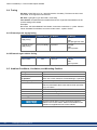
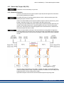
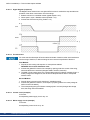
6.15.8.1 Signal diagram (sequence)
The diagram below shows how to use global STO function for a safe drive stop and fault free
operation of the drives connected to one of the strings.
1. Brake the drives in a controlled manner (speed setpoint = 0 V).
2. When speed = 0 rpm, disable the drives (Enable = 0 V).
3. Activate the STO function (STO_Enable = 0 V)
6.15.8.2 Functional test
You must test the safe torque off function after initial start of the drive, after each interference
into the wiring of the drive, or after exchange of one or several components of the drive.
First Method:
1. Stop drives in the string with setpoint 0 V. Keep drives enabled.
DANGER: Do not enter hazardous area!
2. Activate the global STO function for example by opening protective screen of the string,
where the drives are connected (voltage at AKD-C X16/6 or X16/8 0V).
3. The AKD-C fault contact opens, the corresponding string STO-Status message (X16/1 or
X16/2) changes the voltage level, the drives lose torque and slow down to zero speed
without control.
Second Method:
1. Stop all drives in the string with setpoint 0 V, disable the string.
2. Activate the global STO function, for example, by opening protective screen (voltage at
AKD-C X16/6 or X16/8 0V)
3. The corresponding string STO-Status message (X16/1 or X16/2) changes the voltage
level, the string cannot be enabled.
6.15.8.3 Control circuit (example)
In Process.
Corresponding mains supply circuit ➜ p. 38
6.15.8.4 Mains supply circuit (example)
In Process.
Corresponding control circuit ➜ p. 38.
38
Kollmorgen | November 2013
AKD-C Installation | 6 Technical description and data
6.16 Shock-hazard Protection
6.16.1 Leakage current
Leakage current via the PE conductor results from the combination of equipment and cable
leakage currents. The leakage current frequency pattern includes a number of frequencies,
whereby the residual-current circuit breakers definitively evaluate the 50 Hz current. For this
reason, the leakage current cannot be measured using a conventional multimeter.
Since the leakage current to PE is more than 3.5 mA, in compliance with IEC61800-5-1 the
PE connection must either be doubled or a connecting cable with a cross-section >10 mm²
must be used. Deviating measures according to regional standards might be possible
6.16.2 Residual current protective device (RCD)
AKD-C with AKD-N can cause a d.c. current in the protective earthing conductor. Where a
residual current-operated protective (RCD) or monitoring (RCM) device is used for protection
in case of direct or indirect contact, only an RCD or RCM of Type B is allowed on the supply
side of AKD-C.
In conformity with IEC 60364-4-41 – Regulations for installation and IEC 60204 – Electrical
equipment of machinery, residual current protective devices (RCDs) can be used provided
the requisite regulations are complied with.
The AKD-C is a 3-phase system with a B6 bridge. Therefore, RCDs which are sensitive to
all currents must be used in order to detect any DC fault current.
Rated residual currents in the RCDs:
10 to 30 mA
Protection against "indirect contact" (personal fire protection) for stationary
and mobile equipment, as well as for "direct contact".
50 to 300 mA
Protection against "indirect contact" (personal fire protection) for stationary
equipment
If you use a selective RCD, the more intelligent evaluation process will prevent spurious tripping of the RCD.
6.16.3 Isolating transformers
When protection against indirect contact is absolutely essential despite a higher leakage current, or when an alternative form of shock-hazard protection is sought, the AKD can also be
operated via an isolating transformer (schematic connection ➜ p. 53).
A ground-leakage monitor can be used to monitor for short circuits.
Keep the length of wiring between the transformer and the drive as short as possible.
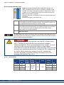
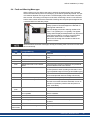
6.17 LED Display
The LED seven-segment display indicates the status
of the drive after the 24 V supply is switched on. If the
service connection to the PC or to the PAC doesn't
work, then the LED display is the only way to get information.AKD fault codes or warning codes are displayed constantly if present. Fault messages are
coded with "F" or "E", warnings are coded with "n".
The IP address can be flashed across the LED display if the B1 button is pressed.
The local fieldbus status LEDs are described in "Local Fieldbus (X20B, X21B)" (➜ p. 63).
Kollmorgen | November 2013
39
AKD-C Installation | 7 Mechanical Installation
7 Mechanical Installation
40
7.1 Important Notes
41
7.2 Mechanical Drawings
42
7.3 Mounting Example
43
Kollmorgen | November 2013
AKD-C Installation | 7 Mechanical Installation
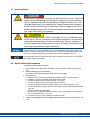
7.1 Important Notes
There is a danger of electrical shock by high EMC level which could
result in injury, if the drive (or the motor) is not properly EMC-grounded.
Protect the device from impermissible stresses. In particular, do not let any components
become bent or any insulation distances altered during transport and handling. Avoid contact
with electronic components and contacts.
The device will switch itself off in case of overheating. Ensure that the mounting space
matches the requirements ("Ambient Conditions, Ventilation, and Mounting Position" (➜ p.
26)).
Do not mount devices that produce magnetic fields directly beside the drive. Strong magnetic fields can directly affect internal components. Install devices which produce magnetic
field with distance to the AKD-C and/or shield the magnetic fields.
Kollmorgen | November 2013
41
AKD-C Installation | 7 Mechanical Installation
7.2 Mechanical Drawings
7.2.1 Dimensions
42
Kollmorgen | November 2013
AKD-C Installation | 7 Mechanical Installation
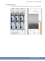
7.3 Mounting Example
Mounting material: Four M5 hexagon socket screws to ISO 4762, 4 mm T-handle Allen key.
Kollmorgen | November 2013
43
AKD-C Installation | 8 Electrical Installation
8 Electrical Installation
44
8.1 Important Notes
45
8.2 Guide to Electrical Installation
45
8.3 EMI Noise Reduction
46
8.4 System Topology of a Decentralized Servo System
48
8.5 Wiring
50
8.6 Connection Overview
51
8.7 Electrical Supply Connection
53
8.8 DC Bus link (X14)
56
8.9 Drive String Connection
62
8.10 I/O Connection
64
8.11 Motion Bus Interface (X10/X11)
68
8.12 Service Interface (X18)
69
8.13 Pushbutton (B1)
70
8.14 Rotary Switches (S1), Setting IP address
71
Kollmorgen | November 2013
AKD-C Installation | 8 Electrical Installation
8.1 Important Notes
Never remove electrical connections to the drive while it is live. There is a
danger of electrical arcing with damage to contacts and serious personal
injury. Capacitors can still have dangerous voltages present up to 7 minutes after switching off the supply power. Always measure the voltage in
the DC bus link at connector X14 and wait until the voltage is below 60 V
before handling components. Control and power connections can still be
live, even if the motor is not rotating.
Since the leakage current to PE is more than 3.5 mA, in compliance with
IEC61800-5-1 the PE connection must either be doubled or a connecting
cable with a cross-section >10 mm² must be used. There is a danger of
electrical shock with possible personal injury. Deviating measures according to regional standards might be possible.
Wrong DC Bus link voltage, unsuitable motor or wrong wiring will damage the system components. Check the combination of drive and motor. Compare the rated voltage and current
of the units. Implement the wiring according to the connection diagrams: ➜ p. 51.
It is permissible to use the setup software to alter the settings of the device. Any other alterations will invalidate the warranty.
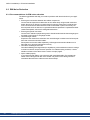
8.2 Guide to Electrical Installation
Install the electrical system as follows:
1. Select cables in accordance with IEC 60204 (➜ p. 28.) and the system topology (➜ p.
48).
2. Install shielding and ground the AKD-C.
Ground the mounting plate and CNC-GND of the control system.
3. Wire the device.
n Wire the FAULT contact in series into the emergency stop circuit of the system.
n If required, connect the external regen resistor (with fusing).
n Connect the required AKD-N drives to string 1 or string 2.
n Connect the Enable input and the digital output, if required.
n Connect the STO inputs and STO status outputs for the used strings (➜ p. 33).
n Connect the auxiliary supply (maximum permissible voltage values see electrical data
(➜ p. 25).
n Connect the main electrical supply.
Check maximum permitted voltage value (➜ p. 25). Check proper use of residual-current circuit breakers (RCD, ➜ p. 39)
n Connect the PC (➜ p. 69) for setting up the drive system.
4. Check the wiring against the wiring diagrams and observe the system topology limits (➜
p. 48).
Kollmorgen | November 2013
45
AKD-C Installation | 8 Electrical Installation
8.3 EMI Noise Reduction
8.3.1 Recommendations for EMI noise reduction
The following guidelines will help you to reduce problems with electrical noise in your application.
l
l
l
l
l
46
Ensure good connections between the cabinet components.
Connect the back panel and cabinet door to the cabinet body using several conductive
braids. Never rely on hinges or mounting bolts for ground connections. Provide an electrical connection across the entire back surface of the AKD-C panel. Electrically-conductive panels such as aluminum or galvanized steel are preferred. For painted and other
coated metal panels, remove all coating behind the drive.
Ensure good ground connection.
Connect from cabinet to proper earth ground. Ground leads should be the same gauge as
the leads to main power or one gauge smaller.
Use Kollmorgen cables.
Experience has shown that customers who use Kollmorgen’s cables have far fewer problems than customers who build cables.
Route power and control cables separately, Kollmorgenrecommends a distance of at
least 200 mm to improve interference immunity.
Ground the shielding at both ends.
Ground all shielding with large areas (low impedance), with metalized connector housings
or shield connection clamps wherever possible. For cables entering a cabinet, connect
shields on all 360° of the cable. Never connect a simple "pigtail".
Splice cables properly.
If you need to divide cables, use connectors with metal backshells. Ensure that both
shells connect along the full 360° of the shields. No portion of the cabling should be
unshielded. Never divide a cable across a terminal stripe
Kollmorgen | November 2013
AKD-C Installation | 8 Electrical Installation
8.3.2 Shielding connection to the drive
8.3.2.1 Shield connection clamps for X12, X13, X14, X15, X16
Shield connection clamps (see accessories manual) are used for connecting cable shields
for X12, X13, X14, X15, X16.
Usually wiring to these connectors must not be shielded.
We recommend using Phoenix Contact SK14 shield clamps with clamp range of 6 to 13mm.
The clamps hook into the grounding plate and ensure optimum contact between the shield
and the grounding plate.
8.3.2.2 Ethernet connectors X10, X11, X18
The shield of Ethernet cables is connected via the connectors to the housing.
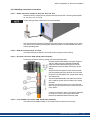
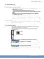
8.3.2.3 DC power connector X20A, X21A (cable CCNCN1)
Connection for the DC power by mating connector with strain relief.
Strip the external cable sheath to a length of approx.
100 mm, taking care not to damage the braided
shield. Push the braided shield (1) back over the
cable and secure with a rubber sleeve (2) or shrink
sleeve.
Shorten all the wires apart from the protective earth
(PE) wire (green/yellow) by about 20 mm so that the
PE wire is now the longest wire. Strip all wires and fit
wire end ferrules.
Secure the braided shield of the cable to the shroud
with a cable tie (3) and use a second tie (4) to fasten
the cable.
Wire the connector as shown in the connection diagram. Plug in the connector to the socket on the front
of the AKD-C.
Screw the connector in place. This ensures that there
is conductive contact over a large surface area
between the braided shield and the front panel.
8.3.2.4 Local fieldbus connectors X20B, X21B (cable CCNCN1)
The shield of local fieldbus cables is connected via the connector to the housing.
Kollmorgen | November 2013
47
AKD-C Installation | 8 Electrical Installation
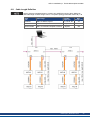
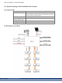
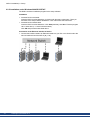
8.4 System Topology of a Decentralized Servo System
8.4.1 System limits
String length:
maximum 100 m total cable length per string
Number of AKD-N:
maximum 8 per string, total maximum 16
observe total power/current restrictions described in the Decentralized System Projecting Guide
Number of AKD-C:
limited by fieldbus protocol
Sum of output current of 17 A, use coincidence factor of the axes for optimization
string 1 and string 2:
Standby total power:
Total standby power is limited to 260 W at 24 V.
Service Interface X18
Ethernet TCP/IP, 100 Mbit/s
8.4.2 Example for one AKD-C
48
Kollmorgen | November 2013
AKD-C Installation | 8 Electrical Installation
8.4.3 Example for several AKD-C
Kollmorgen | November 2013
49
AKD-C Installation | 8 Electrical Installation
8.5 Wiring
There is a danger of electrical arcing which can cause serious personnel
injury. Only install and wire the equipment when it is not live, that is, when
neither the electrical supply nor the 24 V auxiliary voltage nor the supply
voltages of any other connected equipment is switched on.
Make sure that the cabinet is safely disconnected (for instance, with a
lock-out and warning signs). The individual voltages are switched on for
the first time during setup.
Only professional staff who are qualified in electrical engineering are allowed to install the
decentral drive system. Wires with color green with one or more yellow stripes must not be
used other than for protective earth (PE) wiring.
The ground symbol, which you will find in the wiring diagrams, indicates that you must take
care to provide an electrically conductive connection with the largest feasible surface area
between the unit indicated and the mounting plate in the control cabinet. This connection is
for the effective grounding of HF interference, and must not be confused with the PE-symbol
(PE = protective earth, safety measure as per IEC 60204).
Use the following connection diagrams:
Overview AKD-C
Mains supply
24 VDC supply
DC bus link
Drive string connection
Digital I/O
Motion Bus
Service interface
50
Kollmorgen | November 2013
➜
➜
➜
➜
➜
➜
➜
➜
p. 52
p. 54
p. 55
p. 56
p. 62
p. 64
p. 68
p. 69
AKD-C Installation | 8 Electrical Installation
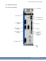
8.6 Connection Overview
8.6.1 Connector assignment
Kollmorgen | November 2013
51
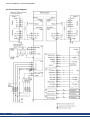
AKD-C Installation | 8 Electrical Installation
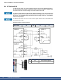
8.6.2 Connection diagram
52
Kollmorgen | November 2013
AKD-C Installation | 8 Electrical Installation
8.7 Electrical Supply Connection
8.7.1 Connection to various mains supply networks
This page illustrates all the possible connection variations for different electrical supply networks.
There is a danger of electrical shock with serious personnel injury if the
device is not properly grounded. An isolating transformer is required for
120V/240V networks to get a minimum voltage of 400 V -10%.
Kollmorgen | November 2013
53
AKD-C Installation | 8 Electrical Installation
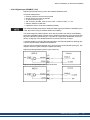
8.7.2 Mains supply connection (X12)
8.7.2.1 Three phase connection
l
l
54
Directly to 3-phase supply network, supply networks ➜ p. 53
Fusing (such as fusible cut-outs) to be provided by the user ➜ p. 26.
Kollmorgen | November 2013
Pin
1
Signal
L1
Description
Line 1
2
L2
Line 2
3
L3
Line 3
4
PE
Protective Earth
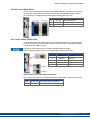
AKD-C Installation | 8 Electrical Installation
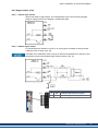
8.7.3 24 VDC supply voltage (X13)
The following diagram describes external 24 VDC power supply, electrically isolated, for
example, via an isolating transformer. The required current rating depends on the use of
motor brake and number of connected AKD-N drives.
The 24 VDC voltage is internally split into a control supply to power the AKD-C electronics
and a supply voltage to power the connected AKD-N drives in case of switched off AC mains
power.
Standby power is limited to 260 W at 24 V for both strings. This power must supply all AKDN ( 8 W each) and the remaining power can be used for motor holding brakes.
Pin
1
Signal
+24
2
GND
Description
+24 VDC Auxiliary voltage
24V Supply GND
Kollmorgen | November 2013
55
AKD-C Installation | 8 Electrical Installation
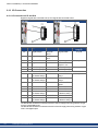
8.8 DC Bus link (X14)
The DC bus link can be connected in parallel so that the regen power is divided between all
the AKD-C that are connected to the same DC bus link circuit. Every AKD-C must have it's
own power connection to mains voltage, even if the DC bus link is used.
The devices can be destroyed if DC bus link voltages are different. Only devices with mains
supply from the same mains (identical mains phases and voltage) may be connected by the
DC bus link. Use unshielded single cores with a maximum length of 200 mm. Use shielded
cables for longer lengths.
The DC-Bus link circuit +DC/-DC is not short circuit proof. Observe the recommended wire
cross section (➜ p. 28).
Possible DC Bus Link connections
Devices
AKD-C01007
56
Kollmorgen | November 2013
AKD-xzzz07
yes
KCM
yes
AKD-xzzz06
no
S3xx / S7xx
no
Pin
3
Signal
-DC
Description
DC-Link Bus negative
4
+DC (+RB)
DC-Link Bus positive
AKD-C Installation | 8 Electrical Installation
8.8.1 Regen resistor (X14)
8.8.1.1 Internal regen resistor
AKD-C has a built-in regen resistor. This internal brake circuit is active with the plugged
bridge in mating connector X14 between 1 (+RBi) and 2 (-RB).
8.8.1.2 External regen resistor
For technical data on the brake circuit ➜ p. 30. Fusing (such as fusible cut-outs) to be provided by the user "Fusing" (➜ p. 26).
The brake circuit +RB/-RB is short circuit proof. Observe the prohibition of continuous, operational short circuits to the external regen resistor contacts (➜ p. 15).
Pin
2
4
Signal Description
-RB
External Regen Resistor negative
+RB
External Regen Resistor positive
Kollmorgen | November 2013
57
AKD-C Installation | 8 Electrical Installation
8.8.2 Capacitor Modules (X14)
KCM modules (KOLLMORGEN Capacitor Modules) absorb kinetic
energy generated by the motor when it is operating in generator mode.
Normally, this energy is dissipated as waste via regen resistors. KCM
modules, however, feed the energy they have stored back into the DC
Bus link as and when it is required.
Assembly information: see regional accessories manual or KCM instruction manual.
Dimensions (HxWxD) : 300x100x201 mm
KCM-S Saves energy: The energy stored in the capacitor module during generative braking is available the next time acceleration happens. The module’s inception voltage is calculated automatically during the first load cycles.
KCM-P
Power in spite of power failure: If the power supply fails, the module provides the
servo amplifier with the stored energy that is required to bring the drive to a standstill in a controlled manner (this only applies to the power supply voltage;
battery-back the 24 V supply separately).
KCM-E Expansion module for both applications. Expansion modules are available in two
capacitance classes.
The KCM modules may only be connected to AKD with 400/480 V rated voltage and a maximum rated current of 24 A. Mounting, installation, and setup instructions can be found in the
Instructions Manual of the KCM Modules.
DC Bus link terminals in servo systems carry high DC voltage of up to
900 V. Touching the terminals while they are carrying voltage is
extremely dangerous. Switch off (disconnect) the line voltage. You must
only work on the connections when the system is disconnected.
It can take over an hour for the modules to self-discharge. Check the state
of charge with a measuring device that is suitable for a DC voltage of up
to 1,000 V. When measuring a voltage of over 60 V between the
DC+/DC- terminals or to ground, discharge the modules (see "Discharging KCM modules" (➜ p. 61)).
8.8.2.1 Technical Data
StorageCapacity
58
Type
KCM-S200
[Ws]
1600
KCM-P200
2000
KCM-E200
2000
KCM-E400
4000
Kollmorgen | November 2013
Rated
Supply
Voltage
[V DC]
Peak
Supply
Voltage
[V DC]
max. 850
max. 950
(30s in 6
min)
Power Protection
Class
[kW]
18
IP20
Inception Weight
Voltage
[V DC]
evaluated
[kg]
6.9
470
6.9
-
4.1
-
6.2
AKD-C Installation | 8 Electrical Installation
8.8.2.2 Example installation with KCM-S and KCM-E
Maximum cable length between AKD-C and KCM: 500mm. The DC+ and DC- lines should
always be twisted, maximum cross section is 6mm². Ensure that the polarity is correct,
swapping round DC+/DC- will damage the KCM modules.
Create a motion profile that causes the brake chopper to respond.
Setup KCM-S and KCM-E
Prerequisite for the following instructions:
l
l
l
l
Properly disconnected, grounded system.
KCM-S: assembled and wired in the switching cabinet. The load that leads to the activation of the brake chopper during braking must be connected.
KCM-E: assembled and connected to the KCM-S with connection cable (X1) and PE line.
Discharge aids (plug-in bridge) are removed.
Proceed as instructed below:
1. Switch on the line voltage.
2. Enable the AKD and operate the motion profile that causes the brake chopper to respond.
3. The KCM-S determines the chopper threshold and begins to charge; LED (top view)
flashes. The energy stored in the capacitor module during generative braking is available
the next time acceleration happens.
Kollmorgen | November 2013
59
AKD-C Installation | 8 Electrical Installation
8.8.2.3 Example installation with KCM-P and KCM-E
Maximum cable length between AKD-C and KCM: 500mm. The DC+ and DC- lines should
always be twisted, maximum cross section is 6mm². Ensure that the polarity is correct,
swapping round DC+/DC- will damage the KCM modules.
The KCM-P starts the charging process at approx. 470 V DC. If the power supply fails, the
module provides the DC bus link with the stored energy (this only applies to the power supply
voltage; battery-back the 24 V supply separately).
Setup KCM-P and KCM-E
Prerequisite for the following instructions:
l
l
l
l
Properly disconnected, grounded system.
KCM-P: assembled and wired in the switching cabinet. Set AKDundervoltage limit
VBUS.UVTHRESH to a value significantly below 470V DC, otherwise AKD will switchoff before KCM-P provides energy to the DC bus link.
KCM-E: assembled and connected to the KCM-P with connection cable (X1) and PE line.
Discharge aids (plug-in bridge) are removed.
Proceed as instructed below:
1. Switch on the line voltage.
2. The KCM-P begins the charging process at approx. 470 V DC; the LED flashes.
60
Kollmorgen | November 2013
AKD-C Installation | 8 Electrical Installation
8.8.2.4 Discharging KCM modules
The aids supplied with each KCM module (plug-in bridge/connecting cables) allows discharging the modules safely.
When the charging LED on top of the modules flashes, the capacitors are charged. Please
note, however, that the LED does not allow you to draw a definite conclusion about the state
of discharge, as it is not monitored for failures.
DC Bus link terminals in servo systems carry high DC voltage of up to
900 V. Touching the terminals while they are carrying voltage is
extremely dangerous.
Switch off the line voltage (disconnect the system). You must only work
on the connections when the system is disconnected.
Check the state of charge of the capacitors with a measuring device that
is suitable for a DC voltage of up to 1,000 V. Wait until the voltage measured between the DC+/DC- terminals or to ground has sunk below 60 V.
It can take over an hour for the modules to self-discharge. If you cannot
wait for the duration of the self-discharge time, you must force the modules to discharge.
You must follow the procedure described below when forcing the modules to discharge.
For your own safety, proceed as follows when forcing the modules to discharge:
1. Switch off (disconnect) the line voltage.
2. Discharge the modules:
KCM-S/-P: Insert the plug-in bridge in the screw terminals (black-1 to gray-2) on the base
of the modules, wait at least 70 s, leave the plug-in bridge in place (as a means of securing for transport). Remove the plug-in bridge again before recommissioning.
KCM-E: Bridge the X2/X3 connector with a connecting cable on the top of the module,
wait at least 70 s, leave the connecting cable in place (as a means of securing for transport). Detach the connecting cable and reconnect the KCM-E properly before recommissioning.
3. Perform the scheduled task (e.g., cleaning, maintenance, or uninstallation).
Kollmorgen | November 2013
61
AKD-C Installation | 8 Electrical Installation
8.9 Drive String Connection
AKD-C support two strings to connect up to 16 AKD-N drives.
For connecting the first AKD-N to one of the DC strings
the Kollmorgen cable type CCNCN1 must be used. This
cable is a Y type adapter with one hybrid connector on the
AKD-N end and two connectors on the AKD-C end with
separate DC power and local fieldbus lines.
8.9.1 String assignment
62
Kollmorgen | November 2013
AKD-C Installation | 8 Electrical Installation
8.9.2 DC power (X20A, X21A)
The DC power lines supply DC power for up to 8 AKD-N drives in one string. Connection for
the DC power must be done by a mating connector with strain relief due to EMC reasons.
This connector is configured with the Kollmorgen CCNCN1 cable (➜ p. 28).
Pin
1
Signal
+DC_ST
Description
DC power positive
2
-DC_ST
DC power negative
3
PE
Protective Earth
8.9.3 Local Fieldbus (X20B, X21B)
Local fieldbus connectors separate for each string enable the AKD-C to communicate with
all connected AKD-N via a four line bus medium. This connector is configured with the Kollmorgen CCNCN1 cable (➜ p. 28).
These ports may not be directly connected to standard EtherCAT nodes.
These connectors are type 1 mini I/O, use Kollmorgen cables CCNCN1 only.
Pin
1
Signal
Receive +
Description
Receive +
2
Receive -
Receive -
3
Transmit +
Transmit +
6
Transmit -
Transmit -
4,5,7,8
n.c.
not connected
Status LEDs for the local fieldbus connections
The communication status is indicated by the built-in status LEDs, one pair for each string.
LED
green
yellow
Name
Function
IN port Link ON = active, OFF= not active
RUN
ON = running, OFF = not running
Kollmorgen | November 2013
63
AKD-C Installation | 8 Electrical Installation
8.10 I/O Connection
8.10.1 I/O connectors X15 and X16
Digital I/O signals are connected to X15, STO signals are connected to X16.
X15 (I/O)
Conn.
X16 (STO)
Pin Signal
Abbreviation Function
Programmable
Wiring
Diagram
➜ p. 66
Enable
Output stage enable
➜ p. 65
DCOM
Common line for
X15 pin 1, 2, 3
X15
1
Digital Output +
DIGITALOUT+
X15
2
Digital Output -
DIGITALOUT-
X15
3
Hardware Enable
X15
4
Digital Common
X15
5
Fault Relay Output Fault
Fault Relay Output
X15
6
Fault Relay Output Fault
Fault Relay Output
X16
1
STO-Status for
STO-Status 1 Status of STO for
DC Power String 1
string 1
X16
2
STO-Status for
STO-Status 2 Status of STO for
DC Power String 2
string 2
X16
3
STO +24 VDC
STO +24 V
24 VDC for STO
signals
X16
4
STO GND
STO GND
GND for STO 24 V
X16
5
STO GND
STO GND
GND for STO 24 V
X16
6
STO-Enable for
STO-Enable 1 Switches off torque
DC Power String 1
for drives in string 1
X16
7
STO GND
X16
8
STO-Enable for
STO-Enable 2 Switches off torque
DC Power String 2
for drives in string 2
STO GND
➜ p. 67
➜ p. 67
GND for STO 24 V
The DCOM line should be connected to the 0V of the I/O supply when using sensors of type
"Source" with digital inputs.
The DCOM line should be connected to the 24V of the I/O supply when using sensors of type
"Sink" with digital inputs.
64
Kollmorgen | November 2013
AKD-C Installation | 8 Electrical Installation
8.10.2 Digital Input (ENABLE, X15)
Digital Input (terminal X15/3) is set to the Hardware Enable function.
Technical characteristics:
l
l
l
l
l
l
Floating, reference common line is DCOM
Sink or Source type wiring is possible
As per IEC61131-2 type 1
ON: 15 VDC to 30 VDC, 2 mA to 15 mA, OFF: -3 VDC to 5 VDC, < 1 mA
Galvanic isolation for 250 VDC
Update rate: direct connection to hardware (FPGA)
The Hardware Enable input and the Software Enable signal (via fieldbus or WorkBench) are
serial, that means wiring of Hardware Enable is mandatory.
The output stage of the AKD-N drives, which are connected to the AKD-C are enabled by
applying the ENABLE signal (Terminal X15/3). Enable is possible only if the input STO-Enable 1 or 2 (valid for DC power strings 1 or 2) has a 24 V signal (see "Global Safe Torque Off
(STO)" on page 33). In the disabled state the connected motor has no torque.
A software enable by means of the setup software is also required (AND link), although this
can also be permanently enabled with WorkBench.
The input can be used with switched +24 V (source type) or switched GND (sink type). See
diagrams below for typical examples of digital input wiring.
Digital Input Wiring Diagram (Source type connection):
Digital Input Wiring Diagram (Sink type connection):
Kollmorgen | November 2013
65
AKD-C Installation | 8 Electrical Installation
8.10.3 Digital Output (X15)
The drive supplies one digital output (X15/1 to X15/2, ➜ p. 64). Choose the required function
in the setup software. Messages from pre-programmed functions stored in the AKD-C can be
output here. A list of these pre-programmed functions can be found in the setup software. If
the output is to be assigned to a pre-programmed function, then the parameter set must be
saved in the AKD-C.
Technical characteristics:
l
l
l
l
l
l
As per IEC61131-2 type 1
Floating, max. 30 VDC, 100 mA
Short circuit proof
Galvanic isolation for 250 VDC
Can be wired as active low or active high (see examples below)
Update rate: 250 µs
Wiring diagram:
66
Kollmorgen | November 2013
AKD-C Installation | 8 Electrical Installation
8.10.4 FAULT relay contacts
Operational readiness (terminals X15/5 and X15/6 ) is signaled by a floating relay contact.
The fault relay can be programmed to two modes of operation:
- Contact closed when there is no fault
- Contact closed when there is no fault and the drive is enabled.
The signal is not influenced by the enable signal, the I²t-limit, or the regen threshold.
Technical characteristics:
l
l
l
FAULT: Relay output, max. 30 VDC or 42 VAC, 1 A
Time to close: max. 10 ms
Time to open: max. 10 ms
All faults cause the FAULT contact to open and the AKD-N output stages to be switched off
(if a fault occurs, the internal hardware ready signal is inhibited -> no power output to motors).
List of the fault messages: ➜ p. 79.
Wiring diagram:
8.10.5 STO signals (X16)
Connector X16 offers access to all STO (Safe Torque Off) signals of the decentral drive system powered by this AKD-C . There is one STO-Enable input and one STO-Status output for
each DC Power string. All STO signals are galvanically isolated and need external 24 VDC
supply (PELV/SELF).
For detailled description of STO interface and functionality refer to "Global Safe Torque Off
(STO)" (➜ p. 33).
Kollmorgen | November 2013
67
AKD-C Installation | 8 Electrical Installation
8.11 Motion Bus Interface (X10/X11)
The motion bus interface has RJ-45 connectors and can be used for communication
with the EtherCAT master and other AKD-C.
Do not connect the Ethernet line for the PC or PAC with the set up software to the motion
bus interface X10/X11. The set up Ethernet cable must be connected to X18.
8.11.1 Pinout
Pin
1
Signal X10
Transmit +
Signal X11
Receive+
2
Transmit -
Receive-
3
Receive+
Transmit +
4, 5
n.c.
n.c.
6
Receive-
Transmit -
7, 8
n.c.
n.c.
8.11.2 Bus Protocols
Protocol
EtherCAT
Type
Connectivity Option
Motion bus
EC
8.11.3 Network configuration
8.11.4 EtherCAT
AKD-C01007-CBEC can be connected as slaves to the EtherCAT network (CoE) via RJ-45
connectors X10 (in port) and X11 (out port).The communication status is indicated by the
built-in connector LEDs.
Connector
X10
X11
LED#
LED1
Name
IN port Link
LED2
RUN
LED3
LED4
68
Kollmorgen | November 2013
Function
ON = active, OFF= not active
ON = running, OFF = not running
OUT port Link ON = active, OFF = not active
-
-
AKD-C Installation | 8 Electrical Installation
8.12 Service Interface (X18)
Operating, position control, and motion-block parameters can be set up by using the setup
softwareWorkBench on an ordinary commercial PC ("Hardware requirements" (➜ p. 75)).
Connect the service interface X18 to an Ethernet interface on the PC directly or via a network switch. The cable can be connected/disconnected to X18 with power on. Confirm that
the link LED on the AKD-C (the green LED on the RJ45 connector) and on your PC (or network switch) are both illuminated. If both lights are illuminated, then you have a good electrical connection.
The X18 service port of an AKD-C does not allow access to AKD-N drives connected to
other AKD-C devices.
8.12.1 Pinout
Pin
1
Signal
Transmit +
Pin
5
Signal
n.c.
2
Transmit -
6
Receive-
3
Receive+
7
n.c.
4
n.c.
8
n.c.
8.12.2 Service Bus Protocols
Protocol
Ethernet TCP/IP
Type
Service Bus, 100 Mbit/s
8.12.3 Possible Network Configurations
Network hubs and transfer rate of 10 Mbit/s are not supported.
Kollmorgen | November 2013
69
AKD-C Installation | 8 Electrical Installation
8.13 Pushbutton (B1)
.
The pushbutton can be used to start predefined functions.
Press short to display the IP address in the LED display
70
Kollmorgen | November 2013
AKD-C Installation | 8 Electrical Installation
8.14 Rotary Switches (S1), Setting IP address
You can use the rotary switch S1 to set the IP address of the
AKD-C. The configured IP address (depending on the current
rotary switch S1 position) will be displayed on the 7 segment
at Ethernet cable connection time and at power-on, if an Ethernet cable is connected.. If no Ethernet cable is connected,
no IP address will be indicated in the display.
By default, the AKD-C utilizes the rotary switch to aquire its
IP address. A method of setting the IP address independent
of the rotary switch is available. More information is available
in the AKD-C User Guide or in the Settings Screen-> Fieldbus-> TCP/IP screen in WorkBench.
S1 Setting AKD-C IP Address
0
DHCP/AutoIP address. The IP address of the AKD-C is obtained from the
DHCP server on your network. If no DHCP server is found the IP addresses
is an AutoIP address (it is internally generated following the AutoIP protocol
and will be of the form 169.254.x.x).
1 to 9
Static IP Address. The IP address is 192.168.0.n, where n is the number set
with the rotary switch. This setting generates addresses in a range from
192.168.0.1 to 192.168.0.9. Example:if S1 is set to 5 – the IP address is
192.168.0.5
The PC subnet mask must be set to 255.255.255.0 or 255.255.255.128
Static IP addressing
When connecting the AKD-C directly to a PC, static IP addressing must be used. Set rotary
switch S1 to a number from 1 to 9. This setting generates addresses in a range from
192.168.0.1 to 192.168.0.9.
Example: if S1 is set to 5, then the IP address is 192.168.0.5
Dynamic IP addressing (DHCP and Auto-IP)
With S1 set to 0, the device is in DHCP mode. The AKD-C will acquire its IP address from
an external DHCP server if present in the network. If a DHCP server is not present, the
AKD-C will assume an Automatic Private IP Address of the form 169.254.x.x.
If your PC or PAC is directly connected to the AKD-C , and set to obtain an IP address automatically in the TCP/IP settings, a connection will be established with both devices using
compatible automatic generated addresses. It can take up to 60 seconds for a PC to configure an Automatic Private IP Address (169.254.x.x).
Changing the IP address
If the switch is altered while 24 V Logic power is supplied to the AKD-C , you must switch off
and then switch on again the 24 V supply voltage. This action will reset the address.
Kollmorgen | November 2013
71
AKD-C Installation | 9 Setup
9 Setup
72
9.1 Important Notes
73
9.2 Setup software WorkBench
74
9.3 Initial System Test
77
9.4 Fault and Warning Messages
79
9.5 Troubleshooting the AKD-C
81
Kollmorgen | November 2013
AKD-C Installation | 9 Setup
9.1 Important Notes
Before testing and setup, the manufacturer of the machine must generate a risk assessment
for the machine and take appropriate measures so that unforeseen movements cannot cause
injury or damage to any person or property.
Only professional personnel with extensive knowledge in the fields of electrical engineering
and drive technology are allowed to test and set up the drive.
The equipment produces potentially lethal voltages up to 900 V. Risk of
electrical shock. Check that all connection components that are live in
operation are safely protected against bodily contact.
Never remove the electrical power connections to the drive while it is live.
Capacitors can still have dangerous residual charges up to 7 minutes
after switching off the supply voltage.
The drive might restart automatically after power on, depending on the
parameter setting. Risk of death or serious injury for humans working in
the machine. If parameter DRV.ENDEFAULT for one AKD-N is set to 1,
then place a warning sign to the machine (Warning: Automatic Restart at
Power On) and ensure, that power on is not possible, while humans are
in a dangerous zone of the machine.
Additional information on setting up the equipment:
l
l
Programming parameters and control loop behavior are described in the online help of the
setup software.
Kollmorgencan provide training courses for the drive upon request.
Kollmorgen | November 2013
73
AKD-C Installation | 9 Setup
9.2 Setup software WorkBench
This chapter describes the installation of the setup software WorkBench for AKD-C and
AKD-N drives.
Kollmorgen offers training and familiarization courses on request.
9.2.1 Use as directed
The setup software is intended to be used for altering and saving the operating parameters for
the AKD series of products. The attached devices can be set up with the help of this software, and during this procedure the drive system can be controlled directly by the service
functions.
Only professional personnel who have the relevant expertise (➜ p. 13) are permitted to carry
out online parameter setting for a drive that is running. Sets of data that have been stored on
data media are not safe against unintended alteration by other persons. Unexpected move
could be the result if you use unchecked data. After loading a set of data you must therefore
always check all parameters before enabling the drive.
74
Kollmorgen | November 2013
AKD-C Installation | 9 Setup
9.2.2 Software description
Each device must be adapted to the requirements of your machine. For most applications,
you can use a PC and WorkBench (the setup software) to set up the operating conditions
and parameters. The PC is connected to the AKD-C by an Ethernet cable (➜ p. 69). The
setup software provides the communication between the PC and every AKD-N drive connected to this AKD-C. You can find the setup software on the accompanying DVD and in the
download area of the Kollmorgen website.
With very little effort you can alter parameters and instantly observe the effect on the drive,
since there is a continuous (online) connection to the AKD-C. You can also read important
actual values from drives, which are displayed on the monitor of the PC (oscilloscope functions).
You can save sets of data on data media (archiving) and load them them into other AKD-C or
use them for backup. You can also print out the data sets.
Most standard feedbacks (SFD, EnDAT 2.2, 2.1, and BiSS) are plug and play compatible.
Motor nameplate data is stored in the feedback device and read by the drive automatically at
startup. Non-plug and play Kollmorgen motors are stored in WorkBench and can be loaded
with one-click using the Motor screen in the WorkBench software.
An extensive online help with integrated description of all variables and functions supports
you in each situation.
9.2.3 Hardware requirements
The Service interface (X18, RJ45) is connected to the Ethernet interface of the PC by an Ethernet cable (➜ p. 69).
Minimum requirements for the PC:
Processor: at least Pentium® II or comparable
Operating system : Windows 2000 or XP or VISTA or 7
Graphics adapter : Windows compatible, color
Data Drives : hard disk with at least 20 MB free space, DVD drive
Interface : one free Ethernet Interface, or a Switch port, 100 Mbit/s
9.2.4 Operating systems
Windows 2000/XP/VISTA/7
WorkBench works with Windows 2000, Windows XP, Windows VISTA and Windows 7
Unix, Linux
The functioning of the software has not been tested for Windows running with Unix or Linux.
Kollmorgen | November 2013
75
AKD-C Installation | 9 Setup
9.2.5 Installation under Windows 2000/XP/VISTA/7
The DVD includes an installation program for the setup software.
Installation
l
l
Autostart function activated:
Insert the DVD into a free data drive. A window with the start screen opens. There you
find a link to the setup software WorkBench. Click it and follow the instructions.
Autostart function deactivated:
Insert the DVD into a free data drive. Click Start (task bar), then Run. Enter the program
call: x:\index.htm (x = correct DVD drive letter).
Click OK and proceed as described above.
Connection to the Ethernet interface of the PC
l
76
Connect the interface cable to an Ethernet interface on your PC or to a Switch and to the
service interface X18 of the AKD-C (➜ p. 69).
Kollmorgen | November 2013
AKD-C Installation | 9 Setup
9.3 Initial System Test
9.3.1 Unpacking, mounting, and wiring
l
l
l
l
l
l
Unpack the AKD-C and accessories. Observe the safety instructions in the documentation.
Mount the AKD-C (➜ p. 40ff).
Connect the AKD-N via the hybrid cables to the AKD-C (➜ p. 44ff).
Connect motors to the connected AKD-N. See AKD-N Installation Manual for more information.
Make sure you have on hand the following information about the drive components:
n rated mains supply voltage
n motor type (motor data, if the motor type is not listed in the motor database)
n feedback unit built into the motor (type, poles/lines/protocol)
n moment of inertia of the load
Connect a PC with the installed WorkBench setup software to connector X18. See AKDC Installation Manual for more information.
9.3.2 Set IP address
The AKD-C node address can be set with the rotary switch (➜ p. 71), with the WorkBench
setup software or via the fieldbus.
9.3.3 Confirm connections
Switch on 24 VDC logic power for the system through the AKD-C X13 connector (mains
supply voltage is not needed for communications).
Confirm that the green link LEDs on the AKD-C and on the PC are both illuminated.
While the PC is connecting, your statusbar will show the following acquiring icon:
Wait for this icon to change to the limited functionality icon (this process can take up to one
minute).
Although Windows displays this limited functionality icon for the drive connection, the PC
can communicate fully with the drive. Using WorkBench, you can now configure the drive
through this connection.
Kollmorgen | November 2013
77
AKD-C Installation | 9 Setup
9.3.4 Install and start WorkBench
WorkBench installs automatically from the DVD included with the drive. WorkBench is also
available on the Kollmorgen Web site: www.kollmorgen.com.
Once installation is complete, click the WorkBench icon to start the program. WorkBench
will show a list of all the drives that it can find connected to the AKD-C.
Select the AKD-C you wish to configure and then click Next.
If multiple devices are detected, a device can be uniquely identified using one of the following
methods:
1. The MAC address of the device. This address is printed on the sticker on the side of the
drive.
2. The name of the devices. The device name is set using WorkBench. A new device
defaults to “No_Name.”
3. Blinking the display. Select a device and click Blink to force the display on the front of the
drive to blink on and off for 20 seconds.
9.3.5 Enable the drive using the setup wizard
Once a connection to the AKD-C has been established, all AKD-N connected to this device
are listed. Select one of these drives and the AKD Overview screen appears. Your drive
appears in the navigation area on the left of the screen. Right click on your drive name and
select Setup Wizard from the drop-down menu. The Setup Wizard guides you through the initial drive configuration, which includes a simple test motion.
After completing the Setup Wizard, your drive should be enabled. If the drive is not enabled,
check the following:
1. The hardware enable (HW) for the drive strings must be in the enabled state (pin 3 on
AKD-C X15 connector).
2. The software enable (SW) must be in the enabled state. Activate using the Enable/Disable button on the upper toolbar on WorkBench or in the Overview screen.
3. No faults may be present (click the Clear Fault button on the upper tool bar to clear any
faults).
The status of HW enable, SW enable, and Faults is displayed in the lower toolbar of the
WorkBench software. The drive is connected if the lower right corner shows Online.
You can now use the Settings View in WorkBench to complete advanced configuration of
your drive.
78
Kollmorgen | November 2013
AKD-C Installation | 9 Setup
9.4 Fault and Warning Messages
When a fault occurs, the AKD-C fault relay is opened, the output stage of the connected
AKD-N are switched off (motors lose all torque), or the load is dynamically braked. The specific behavior depends on the type of fault. The LED display shows the number of the fault
that occurred. If a warning is issued prior to the fault, the warning is shown on the LED and
has the same number as the associated fault. Warnings do not trip the power stages of the
connected AKD-N or fault relay output.
AKD fault codes or warning codes are displayed constantly if present. Fault messages are coded with "F",
warnings are coded with "n".
The LED displays the fault or warning number as follows: F-1-0-1-[break] or n-1-0-1-[break]. The highest
priority fault is displayed. Multiple faults may be present
when a fault condition is occurring. Check the AKD
WorkBench Fault Screen or read the status of
DRV.FAULTS through the controller or HMI for the
entire list of faults.
More information about fault messages, remedy and clearing faults can be found in the WorkBench online help.
Fault
F0
Message/Warning
Cause
Reserved.
F101
Firmware type mismatch.
Installed firmware is not compatible with the drive hardware.
n101
The FPGA is a lab FPGA.
The FPGA is a lab version FPGA.
F102
Resident firmware failed.
Software failure detected.
n102
Operational FPGA is not a default
FPGA.
The FPGA minor version is larger than the operational
firmware default FPGA minor version
F103
Resident FPGA failed.
Software failure detected. Load resident FPGA failure
occurred (several cases according to flowchart, including incompatible image to FPGA type and fieldbus type).
F104
Operational FPGA failed.
Software failure detected. Load operational FPGA failure occurred (several cases according to flowchart).
F105
Non-volatile memory stamp invalid.
Non-volatile memory stamp is corrupted or invalid.
F106
Non-volatile memory data
Non-volatile memory data is corrupted or invalid. When
this fault occurs after a firmware download, it is not an
indication of a problem (clear the fault and perform a
“save” to the drive).
F125
n125
Synchronization lost
The fieldbus lost synchronization.
F136
Firmware and FPGA versions are
not compatible
The FPGA version does not match the firmware FPGA
version constants.
F201
Internal RAM failed.
Hardware failure detected.
F202
External RAM failed.
Hardware failure detected.
F203
Code integrity failed.
Software failure detected. FPGA register access failure
occurred.
F204 to F232 EEPROM failure detected
EEPROM failure detected
F234 to F237 Temperature sensor high.
n234 to n237
High temperature limit reached.
Kollmorgen | November 2013
79
AKD-C Installation | 9 Setup
Fault
Message/Warning
F240 to F243 Temperature sensor low.
n240 to n243
80
Cause
Low temperature limit reached.
F501
n501
Bus over voltage.
Bus voltage too high. Usually, this problem is load
related.
F503
n503
Bus capacitor overload.
Single phase AC input on a drive only rated for threephase input or excessive single-phase power load.
F519
Regen short circuit.
Regen resistor short circuit.
F521
n521
Regen over power.
Too much power stored in regen resistor.
F523
Bus over voltage FPGA
Bus over voltage hard fault.
F531
Power stage fault.
Hardware failure detected.
F536
Standby power supply fault.
Loss of standby power. F537
Precharge fault.
Precharge process could not performed successfully.
F541
AC Input Phase L1 missing
Mains supply failure detected, phase L1 missed
F542
AC Input Phase L2 missing
Mains supply failure detected, phase L2 missed
F543
AC Input Phase L3 missing
Mains supply failure detected, phase L3 missed
F545
Drive String current over peak limit
String current too high
F546
Drive String current over continuous
limit
String current too high
F560
More than eight AKD-N connected to Too many drives at string 1
string 1
F561
More than eight AKD-N connected to Too many drives at string 2
string 2
F564
Number of connected AKD-N at
string 1 decreased
Drive has been removed from string 1
F565
Number of connected AKD-N at
string 1 decreased
Drive has been removed from string 1
F621
Control Board CRC fault.
Hardware failure detected
F623
Power Board CRC fault.
Hardware failure detected
F624
Power Board Watchdog fault.
Hardware failure detected
F625
Power Board Communication fault.
Hardware failure detected
F626
Power Board FPGA not configured.
Hardware failure or faulty configuration
F627
Control Board Watchdog fault.
Hardware failure detected
F702
n702
Fieldbus communication lost.
All fieldbus communication was lost.
Kollmorgen | November 2013
AKD-C Installation | 9 Setup
9.5 Troubleshooting the AKD-C
Drive problems occur for a variety of reasons, depending on the conditions in your installation. The causes of faults in multi-axis systems can be especially complex. If you cannot
resolve a fault or other issue using the troubleshooting guidance presented below, customer
support can give you further assistance.
More details on the removal of faults can be found in the WorkBench online help.
Problem
Possible Causes
Remedy
HMI message:
l wrong cable used, cable plugged
l plug cable into the correct sockets on
Communication fault
into wrong position on drive or
the drive and PC
PC
l select correct interface
l wrong PC interface selected
Drive strings do not
enable
l
HW Enable not wired
HW or SW Enable not set
l
l
During installation,
the message “Please
wait while the
installer finishes
determining your
disk space requirements” appears and
never disappears.
l
MSI installer issue.
l
l
Harddisk space not sufficient
l
l
connect HW Enable (X15 pin 3)
Apply 24V to HW Enable and select
SW Enable in WorkBench / Fieldbus
Cancel the installation. Relaunch the
installer (you may need to try several
times, the problem is random).
Make sure that you have enough disk
space on your hard disk (~500MB to
allow Windows .NET update if necessary), if not make some space.
Kollmorgen | November 2013
81
AKD-C Installation | 9 Setup
This page intentionally left blank.
82
Kollmorgen | November 2013
AKD-C Installation | 10 Index
I
10 Index
A
Abbreviations
AKD Family
Ambient temperature
Aux. supply 24V, interface
10
24
26
55
C
Cable and Wire Requirements
Capacitor Modules
CE conformance
Connection Diagram
Connection Overview
Connector Assignments
Connectors
28
58
19
52
51
51
28
D
DC bus link, interface
DC Power String, interface
Digital inputs
Disposal
Dynamic Braking
56
63
65
17
30
65
26
68
68
F
Fault messages
FAULT relay
Fieldbus String, interface
Fusing
79
67
63
26
G
Grounding
45
H
Hardware requirements
WorkBench
Humidity
in operation
Storage
Transport
64
77
27
65
65
33
44
41
76
K
58
KCM
L
Leakage current
39
M
E
ENABLE
Enclosure protection
EtherCAT
EtherNet
EtherCAT Protocol
I/O-Connection
Initial Drive Test
Inputs
Basic Data
Digital
Enable
STO
Installation
Electrical
Mechanical
Software WorkBench
75
26
16
16
Mains supply, interface
Maintenance
Mounting position
54
16
26
N
Nameplate
Noise Emission
21
26
O
Operating systems
WorkBench
Outputs
Basic Data
Digital
Fault Relay
75
27
66
67
P
Package supplied
Packaging
Part number scheme
PC connection
Pollution level
Prohibited Use
General
STO
Pushbutton B1
21
16
22
69
26
15
34
70
R
Regen circuit
Regen resistor, interface
Kollmorgen | November 2013
30
57
83
AKD-C Installation | 10 Index
Repair
17
S
Safe Torque Off (STO)
Safety
Safety Instructions
STO
Service Interface
Setup
Setup Software
WorkBench
Shielding
Shock-hazard protection
Site altitude
Stacking height
Stacking Height
Transport
Stacking Height, Storage
Standards used
STO
STO signals
Storage
Supply networks
Switch-on/switch-off behavior
Symbols used
33
12
35
69
73-74
74
45
39
26
16
16
16
11
33
67
16
53
31
9
T
Temperature
in operation
Storage
Transport
Tightening torques, connectors
Transport
Trouble Shooting
26
16
16
28
16
81
U
Uninstalling
Use as directed
Drive
STO
WorkBench Setup Software
17
15
34
74
V
Ventilation
Ambient Conditions
Vibrations
26
26
W
Warnings
Wiring
84
Kollmorgen | November 2013
79
50
AKD-C Installation | 10 Index
This page intentionally left blank.
Kollmorgen | November 2013
85
AKD-C Installation | 10 Index
This page intentionally left blank.
86
Kollmorgen | November 2013
AKD-C Installation | 10 Index
This page intentionally left blank.
Kollmorgen | November 2013
87
About KOLLMORGEN Kollmorgen is a leading provider of motion systems and components for machine builders. Through worldclass knowledge in motion, industry-leading quality and deep expertise in linking and integrating standard and
custom products, Kollmorgen delivers breakthrough solutions that are unmatched in performance, reliability
and ease-of-use, giving machine builders an irrefutable marketplace advantage. For assistance with your application needs, visit www.kollmorgen.com or contact us at:
North America
KOLLMORGEN
203A West Rock Road
Radford, VA 24141 USA
Europe
KOLLMORGEN Europe GmbH
Pempelfurtstraße 1
40880 Ratingen, Germany
Asia
KOLLMORGEN
Rm 2205, Scitech Tower, China
22 Jianguomen Wai Street
Web:
Mail:
Tel.: Fax: Web:
Mail:
Tel.: Fax: Web: www.kollmorgen.com
Mail: [email protected]
Tel.: +86 - 400 666 1802
Fax: +86 - 10 6515 0263
www.kollmorgen.com
[email protected]
+1 - 540 - 633 - 3545
+1 - 540 - 639 - 4162
www.kollmorgen.com
[email protected]
+49 - 2102 - 9394 - 0
+49 - 2102 - 9394 - 3155