1
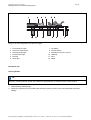
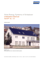
Solar Energy Systems of Schweizer:
Installation Manual
Solrif® XL / D
September 2009
®
Solrif XL / D
Mounting Directions for In-Roof Photovoltaic Systems
Ernst Schweizer AG, Metallbau, CH-8908 Hedingen, Telefon +41 44 763 61 11, Telefax +41 44 763 61 19, www.schweizer-metallbau.ch
Contents
1
2
3
4
6
7
8
9
About this Installation Manual
1.1 Revisions
1.2 Validity
1.3 Target Group
1.4 Warnings, Symbols, Displays
1.4.1
Warnings in this Document
1.4.2
Symbols and Displays
Safety Instructions
2.1 Use According to Regulations
2.2 Safety Regulations
2.3 Personnel Qualifications
2.4 Changes and Alterations
2.5 Sources of Danger
2.5.1
Electrical Installation
2.5.2
Working on the Roof
Instructions
3.1 Overview
®
3.2 Solrif -framed Photovoltaic Modules
3.3 Substructure
3.5 Required Components for In-Roof Mounting / Flashing
3.5.1
Flashing profiles
3.5.2
Flashings
3.5.3
Eaves Skirting, Sealing Tape for Seams and Clamps for the Lower Seam
Mounting
4.1 Tools, Auxiliary Material
4.2 Preliminary Steps
4.2.1
Structure Statics in Accordance with DIN 1055/Eurocode 1
4.2.2
General Planning
4.3 Wiring
4.4 In-Roof Mounting
4.4.1
Installing the Photovoltaic Modules
4.4.2
Roof Seams
4.5 Potential Equalization and Lightning Protection
Dismounting
Control
Disposal
List of Parts
®
9.1 Accessories for Solrif XL
®
9.2 Accessories for Solrif D
Ernst Schweizer AG, Metallbau, CH-8908 Hedingen, Telefon +41 44 763 61 11, Telefax +41 44 763 61 19, www.schweizer-metallbau.ch
4
4
4
4
4
4
5
5
5
6
5
6
6
7
7
7
8
8
9
12
13
15
18
20
20
21
21
21
24
25
25
32
40
40
41
41
41
41
42
Solar Energy Systems 01.09.2009
Mounting Directions for In-Roof Photovoltaic Systems
1
Page 3
About this Installation Manual
These instructions describe a quick and reliable in-roof installation of the photovoltaic system.
Read this manual carefully before starting with the installation.
Keep this manual for as long as the photovoltaic system is in use.
Be sure that this manual can be made available to the operator at all times.
Hand this manual on to all subsequent owners or users of the photovoltaic system.
Insert all supplemental information received from the producer.
Heed all other applicable documents.
1.1
Revisions
Date
Version
What’s new?
12 Feb. 2009
1
complete update
20 April 2009
1.1
potential equalization supplement
Table 1-1:
1.2
Revisions
Validity
®
This manual is valid exclusively for the installation of Ernst Schweizer AG photovoltaic modules Solrif XL and
®
Solrif D.
1.3
Target Group
This manual is intended for installers of photovoltaic systems as well as for qualified technicians specializing in the
mounting, operating and maintenance of photovoltaic systems.
1.4
Warnings, Symbols, Displays
1.4.1
Warnings in this document
In this instruction manual warning signs are used in order to prevent injuries and damages.
Read and always heed these warning signs.
Warnings are marked by the following symbols and terms:
DANGER
Imminent Danger.
Negligence could lead to death or serious injury.
WARNING
Impending Danger.
Negligence could lead to death or serious injury.
Ernst Schweizer AG, Metallbau, CH-8908 Hedingen, Telefon +41 44 763 61 11, Telefax +41 44 763 61 19, www.schweizer-metallbau.ch
Solar Energy Systems 01.09.2009
Mounting Directions for In-Roof Photovoltaic Systems
CAUTION
Dangerous Situation.
Negligence could lead to injury.
CAUTION
Critical Situation.
Negligence could lead to material damage.
1.4.2
Symbols and Displays
In this installation manual symbols and displays are used to facilitate comprehension.
Symbol
Meaning
Prerequisite to this specific stage of
installation.
Installation stage with one or more
steps, the order of which is not
important.
1.
2.
3. ...
Installation stage with several steps, the
order of which is relevant and therefore
listed.
Listing at the first level
–
(cf. chapter)
Table 1-2:
Listing at the second level, including
stage instructions
Cross reference within this installation
manual
Symbols and Displays
TIP
Important information towards understanding or towards optimizing the process of installation.
Ernst Schweizer AG, Metallbau, CH-8908 Hedingen, Telefon +41 44 763 61 11, Telefax +41 44 763 61 19, www.schweizer-metallbau.ch
Page 4
Solar Energy Systems 01.09.2009
Mounting Directions for In-Roof Photovoltaic Systems
2
Safety Instructions
2.1
Use According to Regulations
Page 5
The photovoltaic system is intended solely for the generation of solar power. Mounting is to occur only upon roof
constructions in accordance with the present installation manual.
There is no guarantee for alternative applications, even if analogous. Categorically any such application is not in
accordance with regulations.
2.2
Safety Regulations
The operator of the photovoltaic system is responsible for seeing that all relevant legal regulations and guides are
adhered to.
•
•
•
•
•
•
•
2.3
Start, operate and maintain the photovoltaic system only in accordance with the following regulations and
standards.
Installation manual
Warning labels and tips on the photovoltaic module
Further applicable documents
System specific regulations and requirements
Valid international, national and regional specifications, especially as pertaining to the installation of electrical
appliances and systems, to working with direct current and to the regulations of the local power company
applicable to parallel operation of solar power system
Regulations of the construction employers’ liability insurance association
Regulations concerning accident prevention
Personnel Qualifications
The operator and the installer are responsible for engaging only trained and schooled specialists to carry out
installation, maintenance, initial operation and dismounting.
Ensure all personnel have understood this manual and are capable of implementing the instructions.
Ensure all personnel are familiar with and adheres to the pertinent accident prevention and safety regulations.
Ensure all personnel uses appropriate protective clothing and equipment.
2.4
Changes and Alterations
Changes and alterations to the installation system can damage the photovoltaic module or impair its proper
functioning.
Refrain from making changes or reconstructions during the process of installation, excepting for the steps
described in this manual.
2.5
Sources of Danger
The photovoltaic module is a product made of glass and should be handled as such.
Do not place against bare edging.
Do not step on or burden improperly.
Ernst Schweizer AG, Metallbau, CH-8908 Hedingen, Telefon +41 44 763 61 11, Telefax +41 44 763 61 19, www.schweizer-metallbau.ch
Solar Energy Systems 01.09.2009
Mounting Directions for In-Roof Photovoltaic Systems
2.5.1
Page 6
Electrical Installation
Ensure that the electrical installation and initial operation is carried out by a licensed electrician.
See that the entire off-circuit voltage is hooked up even by minimal sunshine.
Do not exceed the maximum permissible system voltage of the photovoltaic modules even by low
temperatures.
Electric Arcs on Direct Current Conductors!
Simultaneous contact to both poles causes fatal injury.
Do not sever live cables.
Bare cable ends should be connected or insulated.
Voltage Higher than Safety Extra-Low Voltage (SELV)!
Injury to persons due to summation of voltage during series connection
Observe proper safety and security measures.
Dampness During Electrical Installation!
Injury to persons, damage to the system
Carry out work on the system only on a dry undersurface.
During installation see that photovoltaic modules, wiring, etc., are dry.
2.5.2
Working on the Roof
TIP
Safety regulations state that work higher than 3 meters (eaves height) requires scaffolding with safety nets.
If it is not possible to put up scaffolding or if the roof is very steep:
Put on a safety harness and attach it to a stable structure.
Use a proper safety rail when working on the roof.
Arrange for a suitable work surface for tools and material.
Arrange for cordoned off areas to protect against falling objects.
Heed all relevant regulations for working on a roof.
Ernst Schweizer AG, Metallbau, CH-8908 Hedingen, Telefon +41 44 763 61 11, Telefax +41 44 763 61 19, www.schweizer-metallbau.ch
Page 7
Solar Energy Systems 01.09.2009
Mounting Directions for In-Roof Photovoltaic Systems
3
Instructions
3.1
Overview
Image 3-1: Exploded drawing of the photovoltaic system
1
Eaves-side skirting and sealing tape
2
3
4
5
6
7
Sheet grips
Mounting clamp
Cylinder-head screw (5 x 35)
Flashing (left side)
Flashing profile (left)
Mounting board 100 x 30
8
9
10
11
12
13
Batten for roof tiles
Side flashing upper left
Ridge-side flashing left corner
®
Solrif -framed photovoltaic module
Join capping piece
Flashing ridge middle
Ernst Schweizer AG, Metallbau, CH-8908 Hedingen, Telefon +41 44 763 61 11, Telefax +41 44 763 61 19, www.schweizer-metallbau.ch
Page 8
Solar Energy Systems 01.09.2009
Mounting Directions for In-Roof Photovoltaic Systems
®
3.2
Solrif -framed photovoltaic modules
®
®
Solrif -framed modules consist of standard modules mounted with special Solrif profile frames and sealed
watertight.
The profile frames of adjoining modules fit neatly together, thus forming the water runoff level of the roof. Along the
sides impermeability between the overlapping module edges is guaranteed by means of an additional rubber lip.
By roof slopes >10° the rainproof integration of the modules into the roofing is thereby possible in accordance with
guidelines set by the German Roofers’ Association (ZVDH).
®
Ready to mount Solrif -framed photovoltaic modules for in-roof installation can be obtained by various means:
®
Solrif frame kit with framing from Schweizer
Module manufacturers, wholesalers or partners of the Ernst Schweizer AG.
The modules have the following measurements:
Measurement
Lamination
measurement L x W
Framed module (mm)
(L+50) x (W+32)
Laying measurements
(mm)
(L+32) x W
Thickness (mm)
Ca. 34
Mass (kg)
Lamination + ca. 1.5 2.5
Table 3-1:
Measurements of the photovoltaic modules
TIP
Please always consult the current data sheets for the exact specifications of framed modules.
Ernst Schweizer AG, Metallbau, CH-8908 Hedingen, Telefon +41 44 763 61 11, Telefax +41 44 763 61 19, www.schweizer-metallbau.ch
Page 9
Solar Energy Systems 01.09.2009
Mounting Directions for In-Roof Photovoltaic Systems
3
1
4
2
Image 3-2:
SF 130
1
2
3.3
Framed photovoltaic modules (front and backside)
SF 200
Photovoltaic module
®
Solrif -XL profile frames
3
Socket
4
Connecting cable with patch plug
Substructure
The substructure is the basis for the in-roof mounting of the modules. It consists of battens and mounting boards
fastened directly to the roof. It is constructed by means of a grid plan (cf. chapter 4.2.2, p. 26).
3.4
Mounting Clamps
®
Modules framed with Solrif XL profile frames are braced to the substructure with mounting clamps. Three different
types of clamps can be used:
Number
Designation
Article Number
1
Mounting clamp “profile” and “frame”
respectively
13318
1.1
Mounting clamp “profile”, black
06497
2
Mounting clamp “glass” and “module”
respectively
13319
2.1
Mounting clamp “glass”, black
06500
3
Mounting clamp “top”, long, for flat
sheet-metal seams
33954
Table 3-2:
Overview of mounting clamp types
Ernst Schweizer AG, Metallbau, CH-8908 Hedingen, Telefon +41 44 763 61 11, Telefax +41 44 763 61 19, www.schweizer-metallbau.ch
Solar Energy Systems 01.09.2009
Mounting Directions for In-Roof Photovoltaic Systems
Page 10
Mounting Clamp „Profile“
The mounting clamp “profile” is used to brace two modules respectively to their frames in the overlapping area.
This clamp is normally necessary.
Clamp width:
16.5 mm
Material gauge:
1,5 + 2,0 mm
Material:
Stainless spring steel type 1.4310
Screw type:
Cylinder-head screws 5 x 35 high grade (2
screws)
Image 3-3: Mounting clamp “profile”
Mounting Clamp „Glass“
In order to meet the demands of statics, a module can be additionally fastened in the glass area by means of the
mounting clamp “glass”. The necessary number of clamps per module edge is to be determined on the basis of the
grid plan in accordance with the static demands. To protect the glass the front side of the clamp has been coated
with weatherproof plastic.
TIP
The mounting clamp “glass” has been conceived as an additional measure, dependent upon module size and
static demands, not necessary all the time nor in every case.
Clamp width:
16.5 mm
Material gauge:
1,5 + 2,0 mm
Material:
Stainless spring steel type 1.4310
Screw type:
Cylinder-head screws 5 x 35 high grade (2
screws)
Ernst Schweizer AG, Metallbau, CH-8908 Hedingen, Telefon +41 44 763 61 11, Telefax +41 44 763 61 19, www.schweizer-metallbau.ch
Solar Energy Systems 01.09.2009
Mounting Directions for In-Roof Photovoltaic Systems
Page 11
Image 3-4: Mounting clamp “glass”
Mounting Clamp „Top“
The mounting clamp “top” for flat sheet-metal seams is for fastening the highest row of modules from the top. This
clamp is only necessary when flat sheet-metal seams other than those provided by Ernst Schweizer AG are used.
If sheet-metal seams are to be laid from the top, mounting clamps “frame” should be used. The necessary number
of clamps per module edge is to be determined on the basis of the grid plan in accordance with the static demands.
Clamp width:
16.5 mm
Material gauge:
2,0 mm
Material:
Stainless spring steel type 1.4310
Screw type:
Wood or cylinder-head screw 5 x 35 high grade
(2 screws)
Image 3-5: Mounting clamp “top/long flat flashing joins
Ernst Schweizer AG, Metallbau, CH-8908 Hedingen, Telefon +41 44 763 61 11, Telefax +41 44 763 61 19, www.schweizer-metallbau.ch
Page 12
Solar Energy Systems 01.09.2009
Mounting Directions for In-Roof Photovoltaic Systems
3.5
Required Components for In-Roof Mounting / Flashing
Often the module surface of the system, based upon the grid measure of the modules, does not correspond exactly
with the measurements of the roof itself. In this case, the rest of the roof surface must be integrated into the system
by means of flashing profiles and flashings, which can be delivered.
3.5.1
Flashing profiles
For in-roof mounting, special profiles for flashings on the right and left sides of the system are available as an
option. They compose a uniform transition to the seams.
Flashing profile right
3
2
1
Image 3-6: Flashing profile right
1
Flashing seam right side
2
Flashing profile right side
3
Photovoltaic module
Ernst Schweizer AG, Metallbau, CH-8908 Hedingen, Telefon +41 44 763 61 11, Telefax +41 44 763 61 19, www.schweizer-metallbau.ch
Page 13
Solar Energy Systems 01.09.2009
Mounting Directions for In-Roof Photovoltaic Systems
Flashing profile left
1
2
3
3-7:
1
2
Flashing profile left
Flashing seam left side
Flashing profile left side
3
Photovoltaic module
Ernst Schweizer AG, Metallbau, CH-8908 Hedingen, Telefon +41 44 763 61 11, Telefax +41 44 763 61 19, www.schweizer-metallbau.ch
Page 14
Solar Energy Systems 01.09.2009
Mounting Directions for In-Roof Photovoltaic Systems
3.5.2
Flashings
Flashings provide a weatherproof seam to the roof tiles. They have been designed to be able to accommodate
most standard types of roof tiles.
The following flashings are available:
Flashing side (left/right)
Flashing side top (left/right)
Flashing ridge (middle/left/right)
3
4
5
2
6
1
7
1
7
8
Image 3-8: Mounting of the flashings
No.
Designation
1
Flashing side left
2
Flashing side top left
3
Flashing ridge left
(W + 54) x 281 mm
4
Flashing ridge middle
(W + 29) x 281 mm
5
Flashing ridge right
(W + 54) x 279 mm
6
Flashing side top right
281 x 121 mm
7
Flashing side right
773 x 121 mm
8
Photovoltaic modules (laying
measurements)
Table 3-3:
Lamination size L x W
(W + 110) x 121 mm
281 x 121 mm
(L + 31) x W mm
Flashing measurements
Ernst Schweizer AG, Metallbau, CH-8908 Hedingen, Telefon +41 44 763 61 11, Telefax +41 44 763 61 19, www.schweizer-metallbau.ch
Page 15
Solar Energy Systems 01.09.2009
Mounting Directions for In-Roof Photovoltaic Systems
3.5.2.1 Flashing side right/left
Flashings right/left are attached to the flashing profiles and fastened to the mounting board by means of sheet grips
and nails. The flashings are laid upon the modules’ mounting boards and are thus at the same height.
Flashing right side
1
2
3
Image 3-9: Flashing side/right
1
2
Flashing right side
Sheet grips with nails
3
Flashing profile right side
TIP
Fasten the sheets with as many sheet grips as deemed necessary but at least:
Flashing right side/left side: 2 grips
Flashing topside right/left: 1 grip
Ernst Schweizer AG, Metallbau, CH-8908 Hedingen, Telefon +41 44 763 61 11, Telefax +41 44 763 61 19, www.schweizer-metallbau.ch
Page 16
Solar Energy Systems 01.09.2009
Mounting Directions for In-Roof Photovoltaic Systems
Flashing left side
3
2
1
Image 3-10: Flashing side/left
1
2
Sheet grips with nails
Flashing left side
3.5.2.2
3
Flashing profile left side
Flashing upper right/left side
The ridge flashings are laid upon the upper side flashings right/left. They have the same width as the side
flashings. These flashings can be used with all types of modules.
Flashing upper right side
3
4
2
1
6
5
Image 3-11: Flashing side/top/left
1
2
3
Sheet grips with nails
Flashing left side
Flashing upper left side
4
5
6
Flashing ridge left
Photovoltaic module
Flashing profile left side
Ernst Schweizer AG, Metallbau, CH-8908 Hedingen, Telefon +41 44 763 61 11, Telefax +41 44 763 61 19, www.schweizer-metallbau.ch
Page 17
Solar Energy Systems 01.09.2009
Mounting Directions for In-Roof Photovoltaic Systems
Flashing upper left side
3
4
2
1
6
5
Image 3-12: Flashing side/top/left
1 Sheet grips with nails
2 Flashing left side
3 Flashing upper left side
4 Flashing ridge left
5 Photovoltaic module
6 Flashing profile left side
Flashing Ridge
The upper seam consists of individual sheets, each of which is assigned to a module in the upper row.
There are three types of flashings for the upper seam:
Flashing ridge middle
Flashing ridge left side
Flashing ridge right side
4
3
1
2
5
6
8
7
Image 3-13: Flashing ridge
Ernst Schweizer AG, Metallbau, CH-8908 Hedingen, Telefon +41 44 763 61 11, Telefax +41 44 763 61 19, www.schweizer-metallbau.ch
Page 18
Solar Energy Systems 01.09.2009
Mounting Directions for In-Roof Photovoltaic Systems
1
2
3
4
Flashing ridge left
Flashing ridge middle
Join capping piece
Roof tile
5
6
7
8
Flashing upper right side
Flashing ridge right
Flashing right side
Photovoltaic module
The ridge flashings left and right have a special construction and lock into the corner flashings and thus ensure a
rainproof junction. The ridge flashings are joined at the upturn, or bevel fold, by means of a capping sheet, which
also guards against the weather.
3.5.3
Eaves skirting, seam sealing strip and bottom mounting clamps
Lower Seam
The photovoltaic modules can be mounted either directly on the eaves or above the tiles.
For the crossover from the lower array edge to the tiles it is normal to use eaves skirting as for other in-roof fixtures,
such as dormer windows (rolled lead sheet 150 mm or Mage flex aluminum roll black 280 mm available as
accessories).
The sealing strips (valley sealing strips) are mounted on the eaves skirting in order to close off the roof hollows for
small animals and insects.
TIP
It is advisable to lay a 17 mm spacing block underneath the mounting clamp “glass” in the lowest row. This is to
prevent the back side of the module from coming into contact with the fold of the mounting clamp by heavy snow
load.
4
Mounting
4.1
Tools, Auxiliary Material
Have the following tools and other material at hand during the mounting process:
Carpenter’s pencil
String / chalk line
Tape measure and measuring stick
Screwdriver set
Nails for sheet grips
Hammer for sheet grip nails
Level
Wood saw
Sheet metal shears and tongs
Knife
Portable electric screwdriver with T25 bit
Angle grinder (diamond grinding wheel) for removing tile nibs
Multimeter
Ultraviolet-resistant cable ties
Ernst Schweizer AG, Metallbau, CH-8908 Hedingen, Telefon +41 44 763 61 11, Telefax +41 44 763 61 19, www.schweizer-metallbau.ch
Solar Energy Systems 01.09.2009
Mounting Directions for In-Roof Photovoltaic Systems
4.2
Preliminary Steps
4.2.1
Structural Calculations in Accordance with DIN 1055/Eurocode 1
Page 19
TIP
The following specifications should be checked on site by means of the local structural conditions.
Before ordering, determine the structural conditions of the roof with the aid of Schweizer’s dimensioning
program ProSolrif and draw up the parts list, especially the number of mounting clamps.
The “simplified” calculating method is based upon actual tests (maximum clamp load) and load effect in
accordance with DIN 1055 (WLZ 2). This method is appropriate for normal wind and snow conditions.
For higher wind conditions and snow loads the dimensioning must be carried out in accordance with DIN 1055.
4.2.2
General Planning
TIP
The particular design of the generator field should conform with local factors and with the demands of the project.
Size of the Grid
TIP
When calculating the size of the grid, do not forget the overlapping frame profiles.
Calculating the size of the grid:
-
Grid size horizontal: Rhor [mm] = Lamination Width [mm] + 31 mm (frame profile)
-
Grid size vertical: Rver [mm] = Lamination Height [mm]
Generator Panel
TIP
In the case of very large systems it is advisable to calculate by 32 mm in order to allow for tolerances.
1. Multiply the grid measurements by the corresponding number of module columns or module rows:
Ernst Schweizer AG, Metallbau, CH-8908 Hedingen, Telefon +41 44 763 61 11, Telefax +41 44 763 61 19, www.schweizer-metallbau.ch
Page 20
Solar Energy Systems 01.09.2009
Mounting Directions for In-Roof Photovoltaic Systems
-
Generator width [mm] = Rhor [mm] x number of module columns
-
Generator height [mm] = Rver [mm] x number of module rows
2. Include the outer frame profiles, as they have no further overlapping elements:
-
Generator width [mm] + 30 mm (15 mm right and left)
-
Generator height [mm] + 30 mm (top)
3. Include the flashings, as the case may be.
CAUTION
Misinterpretation of the number of mounting clamps in accordance with DIN 1055!
Damage to the roof structure and to the entire photovoltaic system.
Calculate so that the required number of mounting clamps in direct relationship to the given snow load and
wind zone are used.
TIP
®
Contact your Solrif dealer in order to draw up an individual grid plan for the photovoltaic modules.
®
Space the mounting clamps 15 mm away from the upper Solrif profile, so that the modules can be pushed
upwards and removed, if need be, for example for repair work.
Image 4-1: Distance between the mounting clamps
-
If the demands of the structural design require it, set the mounting clamps “glass” in center between the
framing clamps (a given number of “glass” clamps will have to be spaced evenly at the corresponding
pitch.
Ernst Schweizer AG, Metallbau, CH-8908 Hedingen, Telefon +41 44 763 61 11, Telefax +41 44 763 61 19, www.schweizer-metallbau.ch
Page 21
Solar Energy Systems 01.09.2009
Mounting Directions for In-Roof Photovoltaic Systems
R_ver
R_ver
R_ver
R_hoz
R_hoz
R_hoz
Image 4-2: Standard grid plan for a generator array with 9 modules (3x3)
Substructure
WARNING
IEC 61215 (ed.) certification of the modules is only valid in connection with a specifically defined substructure!
Use mounting boards with a cross-section size of 30 x 100 mm for the substructure
Softwood construction
grade timber
Only this minimum cross-section size of the boards guarantees the load transmission of the screws.
Fasten the mounting boards on the roof structure using only appropriate and approved fasteners.
TIP
Heat emitted by the photovoltaic modules decreases the efficiency of the system. Proper ventilation of the
modules will minimize this loss effect.
High module temperatures lessen the system’s efficiency.
Plan for a generous horizontal air gap for ventilating the modules (counter-battens as with a normal roof).
1. Fasten the substructure battens with ample fasteners directly on to the roof.
2. Align the substructure with the position of the mounting clamps for the photovoltaic modules (cf. grid plan).
3. Close off the open cross cut between the eaves-side battens with a protective screen against birds, etc.
4. If possible, convert the roof ridge into an aeration ridge in order to divert the warmth.
®
5. Use eaves-side skirting (lead roll or Mage flex strip) for the crossover from the lower edge of the system to the
tiles.
Ernst Schweizer AG, Metallbau, CH-8908 Hedingen, Telefon +41 44 763 61 11, Telefax +41 44 763 61 19, www.schweizer-metallbau.ch
Page 22
Solar Energy Systems 01.09.2009
Mounting Directions for In-Roof Photovoltaic Systems
4.3
Wiring
TIP
Lay the inverter cables and the circuit connecting cables before installing the modules.
Do not connect the modules in vertical circuits: the modules can have different temperatures and thus
different outputs.
Avoid induction loops when wiring the circuits.
TIP
Only high voltage cables and ultraviolet and heat resistant solar cables are permissible for wiring photovoltaic
systems (e.g., Solarflex 1 x 2.5 mm² or 1 x 4 mm²).
1. Connect the inverter cable to the first module or to the lowest module of the circuit.
2. Connect the modules in horizontal circuits with circuit connecting cables and plugs.
3. Connect the module circuits by means of the circuit connecting cable (not included in the delivery).
4. In case of exposed areas decide on site about the possibility of lightning protection measures.
Image 4-3: Correct laying of cables
1 Cable from the circuit to the inverter
2 Socket
3 Module cable with plug
4 Circuit connecting cable
Ernst Schweizer AG, Metallbau, CH-8908 Hedingen, Telefon +41 44 763 61 11, Telefax +41 44 763 61 19, www.schweizer-metallbau.ch
Page 23
Solar Energy Systems 01.09.2009
Mounting Directions for In-Roof Photovoltaic Systems
4.4
In-Roof Mounting
Load-bearing capacity of the roof construction has been tested.
Roof substructure with tile integration has been constructed.
Roofing underlay of DIN plus quality or British Standard 5250 or similar quality is available.
The entire photovoltaic system has been calibrated on the roof.
Corner points have been marked.
A grid plan has been drafted and the wiring of the individual photovoltaic modules has been plotted.
Safety regulations are adhered to.
Inverting cable has been laid and the photovoltaic modules have been set up with module and circuit cables.
4.4.1
Installing the Photovoltaic Modules
CAUTION
Neglecting Structural Demands!
Use only high grade construction quality 30x100 mm mounting boards for the substructure. With lesser
boards the effective strength of the screws can not be guaranteed.
The photovoltaic modules can be mounted either directly on the eaves or above the tiles.
In Preparation for Mounting on the Eaves
Image 4-4: Roof integration position directly at eaves edge
1
2
3
4
5
Mounting clamps “frame”
Mounting board 30 x 100
Photovoltaic module
Counter-batten
Rafter
6
7
8
9
10
Underlay
Roof furring strip
Eaves flashing
Protective screen
Gutter
Ernst Schweizer AG, Metallbau, CH-8908 Hedingen, Telefon +41 44 763 61 11, Telefax +41 44 763 61 19, www.schweizer-metallbau.ch
Solar Energy Systems 01.09.2009
Mounting Directions for In-Roof Photovoltaic Systems
Page 24
1. Attach the protective screen (9) against birds..
2. Fasten the first and the last mounting clamps “frame” of the lower row on to the mounting board using two
cylinder-head screws (5x35) per clamp.
Image 4-5: Fastening mounting clamp “frame”
3. Line up the two mounting clamps with the chalk line and fasten it.
4. Align the other lowest row mounting clamps according to the grid plan and fasten them.
5. Test the clamps for stability.
6. Inlay the modules.
In Preparation for Mounting on the Tiles
CAUTION
Drainage at the Eaves Skirting
Water damage.
When determining the spacing between mounting board and roof tile make sure of the required minimum
slope to ensure that water can drain off.
Ernst Schweizer AG, Metallbau, CH-8908 Hedingen, Telefon +41 44 763 61 11, Telefax +41 44 763 61 19, www.schweizer-metallbau.ch
Page 25
Solar Energy Systems 01.09.2009
Mounting Directions for In-Roof Photovoltaic Systems
4
3
5
2
1
6
7
8
Image 4-6: Roof eaves integration position on tiles
1
2
3
4
Roof tile
Eaves-side skirting
Mounting clamp “frame”
Channel sealing tape 20 x 60mm
5
6
7
8
Photovoltaic module
Counter-batten
Mounting board 30 x 100mm
Tile batten
1. Fasten the eaves-side skirting on the mounting board (7).
2. Fasten the first and the last mounting clamps “frame” (3) of the lower row on to the rafter using two cylinderhead screws (5x35) per clamp.
3. Line up the two mounting clamps with the chalk line and fasten it.
4. Align the other lowest row mounting clamps according to the grid plan and fasten them.
5. Test the clamps for stability.
6. Apply the channel sealing tape (4).
7. Inlay the modules.
4.4.1.1 Mounting the Modules
CAUTION
Wrong Screws!
Using the wrong screws can damage the mounting clamps and will not ensure the necessary stability.
Only use cylinder-head screws 5x35 (countersunk screw are not permissible).
CAUTION
Installing in the Wrong Direction!
Mind the direction! Start installing from the bottom up!
Due to the lateral overlapping of the individual frame pieces only lay the modules from the right to the left.
TIP
The modules can also be installed column by column, so that the roof remains accessible for the
installation of further rows.
Ernst Schweizer AG, Metallbau, CH-8908 Hedingen, Telefon +41 44 763 61 11, Telefax +41 44 763 61 19, www.schweizer-metallbau.ch
Solar Energy Systems 01.09.2009
Mounting Directions for In-Roof Photovoltaic Systems
Page 26
Image 4-7: Module installation order
TIP
Make sure that the inverter cable and the circuit connecting cables have been installed before installing the
modules.
Lead the module circuit connecting cable to the left before laying the module for contact access to the
following module.
1. In the lowest row of the first column to the right inlay the first photovoltaic module in the mounting clamp.
Thereby mind that the drainage channels of the frame profile are on the left and the open lamination edge on
the bottom.
2. Inlay flashing profiles and if necessary flashings on the right with the frame profiles at the panel edge in the
clamp.
Image 4-8: Mounting the first module
Ernst Schweizer AG, Metallbau, CH-8908 Hedingen, Telefon +41 44 763 61 11, Telefax +41 44 763 61 19, www.schweizer-metallbau.ch
Solar Energy Systems 01.09.2009
Mounting Directions for In-Roof Photovoltaic Systems
Page 27
TIP
Flashing profiles and flashings should be installed with their respective row of modules!
3. Make sure that the mounting clamp “frame” is fit exactly into the slots of the frame profile (fixed point).
Image 4-9: Position of the mounting clamp
4. Take another module and take the plug from the first module and put it into the connecting socket of the next
module.
5. Slide the frame profile of the next module into that of the first one.
Image 4-10: Mounting a further module
Ernst Schweizer AG, Metallbau, CH-8908 Hedingen, Telefon +41 44 763 61 11, Telefax +41 44 763 61 19, www.schweizer-metallbau.ch
Page 28
Solar Energy Systems 01.09.2009
Mounting Directions for In-Roof Photovoltaic Systems
6. Determine the position of the second row of mounting clamps. Mind keeping 15 mm space to the upper edge of
the module.
TIP
It must be possible, where necessary (e.g. repair work), to be able to remove the modules from the row!
Fasten further rows of mounting clamps leaving space X (15 mm) to the modules (cf. image 4-11).
When removing, slide the modules upwards until they are free of the lower clamps.
Image 4-11: Spacing the module clamp to the module
1 Position of reference
2 Mounting clamp
3 Module frame
4 Space X = 12 – 15 mm
7. Fasten the second row of mounting clamps to the rafter and test for stability.
TIP
The system measurement „R space between the mounting clamps“ (cf. image 4-1) is crucial for the correct
installation of the module array and for the resultant optical appearance.
The vertical space between the mounting clamps is a system measurement of the module array and should
thus be adhered to in the rows.
Adjustment of the row space for several rows by respective multiplication of the space measure.
Ernst Schweizer AG, Metallbau, CH-8908 Hedingen, Telefon +41 44 763 61 11, Telefax +41 44 763 61 19, www.schweizer-metallbau.ch
Solar Energy Systems 01.09.2009
Mounting Directions for In-Roof Photovoltaic Systems
Page 29
Image 4-12: Fastening mounting clamps for further rows
8. Inlay the first photovoltaic module in the mounting clamps in the second row to the right. Mind that the notches
of the frame profile, which are facing upwards, are on the left side.
9. Take another module and take the plug from the first module and put it into the connecting socket of the next
module.
10. Slide the frame profile of the next module into that of the first one.
Image 4-13: Mounting modules
11. Mount further rows of mounting clamps and photovoltaic modules as described above.
12. Connect flashing profiles and if necessary flashings to the frame profiles on the left array edge.
Ernst Schweizer AG, Metallbau, CH-8908 Hedingen, Telefon +41 44 763 61 11, Telefax +41 44 763 61 19, www.schweizer-metallbau.ch
Solar Energy Systems 01.09.2009
Mounting Directions for In-Roof Photovoltaic Systems
Page 30
Image 4-14: Mounting flashing profile and flashing on the left side
13. Fasten the top row of the modules:
-
Using mounting clamp ”top long” for sheet-metal seams for connecting directly to the roof ridge, or
-
Using mounting clamp “profile” if flashing “ridge” is required.
Ernst Schweizer AG, Metallbau, CH-8908 Hedingen, Telefon +41 44 763 61 11, Telefax +41 44 763 61 19, www.schweizer-metallbau.ch
Solar Energy Systems 01.09.2009
Mounting Directions for In-Roof Photovoltaic Systems
4.4.2
Page 31
Roof Seams
TIP
Roof seams are necessary when the modules do not completely cover the roof.
Roof Seams left and right
TIP
Make sure that the inverter cables and the circuit connecting cable are installed before beginning with the
mounting of the modules.
TIP
Flashing profiles and flashings should be laid with each respective row of modules!
1. Connect flashing profiles right and left to the frame profiles at the array edge.
2. Connect flashings to the flashing profiles.
Image 4-15: Flashing profile and flashing side/right
Ernst Schweizer AG, Metallbau, CH-8908 Hedingen, Telefon +41 44 763 61 11, Telefax +41 44 763 61 19, www.schweizer-metallbau.ch
Page 32
Solar Energy Systems 01.09.2009
Mounting Directions for In-Roof Photovoltaic Systems
Image 4-16: Flashing profile and lashing side/left
Image 4-17: Fastening flashing with sheet grips
1 Nail
2 Sheet grip
3. Fasten the outer upturn of the flashings with sheet grips and nails.
4. Using the angle grinder with the diamond grinding wheel remove the right or, as the case may be, the left nib of
the tile that is to lie upon the flashing.
5. Cover the rest of the roof with tiles.
TIP
Fasten the side sheets with sheet grips according to need but at least:
Flashing on the right or left side: 2 pieces.
Flashing on the right or left corner: 1 piece.
Ernst Schweizer AG, Metallbau, CH-8908 Hedingen, Telefon +41 44 763 61 11, Telefax +41 44 763 61 19, www.schweizer-metallbau.ch
Page 33
Solar Energy Systems 01.09.2009
Mounting Directions for In-Roof Photovoltaic Systems
1
2
12
3
11
4
5
10
6
9
8
7
Image 4-18: Roof integration on a tiled roof (right)
1
2
3
4
5
6
Photovoltaic module
®
Solrif -XL-profile frame
Flashing profile right
Flashing side right
Roof tile
Sheet grip
7
8
9
10
11
12
Tile batten
Counter-batten
Mounting board 100 x 30 mm
Underlay
Roof
Rafter
Roof Seam Top
Flashing Seams
TIP
Normally, mounting clamps “profile” are suitable for ridge flashings, as a flashing has no glass surface.
1. Fasten flashing side/top/right.
2. Fasten the uppermost row of modules with mounting clamps “profile” to the mounting board and test for
stability.
Ernst Schweizer AG, Metallbau, CH-8908 Hedingen, Telefon +41 44 763 61 11, Telefax +41 44 763 61 19, www.schweizer-metallbau.ch
Solar Energy Systems 01.09.2009
Mounting Directions for In-Roof Photovoltaic Systems
Page 34
Image 4-19: Flashing ridge/right
3. Fit the flashings into the last row of mounting clamps:
-
Fasten flashing ridge/left above the uppermost left module. Make sure that the flashing overlaps flashing
side/top/left.
-
Fasten flashing ridge/right above the uppermost right module. Make sure that the flashing overlaps flashing
side/top/right.
-
Fasten flashing ridge/middle above the center modules.
Image 4-20: Flashing ridge/middle
Ernst Schweizer AG, Metallbau, CH-8908 Hedingen, Telefon +41 44 763 61 11, Telefax +41 44 763 61 19, www.schweizer-metallbau.ch
Page 35
Solar Energy Systems 01.09.2009
Mounting Directions for In-Roof Photovoltaic Systems
4. Connect the individual flashings with a join capping piece profile (cf. Image 3-13, p. 17).
Image 4-21: Placing the join capping piece profile
5. Cover the rest of the roof surface with tiles.
Image 4-22: Roof integration on a tiled roof (ridge)
1 Photovoltaic module
2 Mounting clamp “profile”
3 Flashing ridge
4 Roof tile
5 Tile batten
6 Mounting board
TIP
Warmth emitted from the photovoltaic modules lessens the system’s output. Sufficient ventilation of the modules
minimizes the output loss.
High module temperatures lessen the system’s output.
Ventilation in the counter-batten area reduces module temperature and diverts the warmth up and away.
Do not obstruct the free movement of air between the counter-battens.
Divert the ventilation cross section of the counter-battens across the module array and up and away.
Convert the roof ridge into a ventilating ridge with enough ventilation cross sections.
Ernst Schweizer AG, Metallbau, CH-8908 Hedingen, Telefon +41 44 763 61 11, Telefax +41 44 763 61 19, www.schweizer-metallbau.ch
Page 36
Solar Energy Systems 01.09.2009
Mounting Directions for In-Roof Photovoltaic Systems
Seams without Flashings
1. Fasten the top row of the modules to the rafters by means of mounting clamps “long” for flashing “top” and test
for stability.
2. Fasten sealing tape (rolled sheet lead or Mage flex strip) to the mounting board.
3. Cover the upper array edge directly with a ridge tile.
Image 4-23: Integration without flashings
1 Photovoltaic module
2 Mounting clamp “long” for flat topside flashing
3 Sealing tape
4 Ridge tile
5 Mounting board
6 Ventilation ridge
TIP
Warmth emitted by the photovoltaic modules lessens the system’s output. Sufficient ventilation of the modules
minimizes this output loss.
High module temperatures lessen the system’s output.
Ventilation in the counter-battens reduces the module temperature and diverts the warmth up and away.
Do not obstruct the circulation of air between the counter-battens with built-in components.
Convert the roof ridge into a roof ridge ventilation system with sufficient cross-ducts.
Ernst Schweizer AG, Metallbau, CH-8908 Hedingen, Telefon +41 44 763 61 11, Telefax +41 44 763 61 19, www.schweizer-metallbau.ch
Page 37
Solar Energy Systems 01.09.2009
Mounting Directions for In-Roof Photovoltaic Systems
4.5
Potential Equalization and Lightning Protection
CAUTION
Voltage via Residual Current or Capacitive Charging
Electric shock upon contact with metal parts is possible and can result in damage or injury.
Prevent personal injury by correctly conducting potential equalization.
Potential Equalization
TIP
It is generally recommended to ground the photovoltaic generator and to link it to potential equalization. Potential
equalization is of the utmost importance in the following cases:
Non-transformer inverter
Existent lightning protection system with proper distancing
Establish potential equalization in accordance with DIN VDE 0100 or with the corresponding national
regulations as protection against electric shock.
®
It is possible to drill two holes in the upper frame profile of the Solrif modules in order to link to the potential
equalization. If necessary screws and tags can be fastened there securely (cf. image 4-25).
Image 4-24: Holes drilled for potential equalization
Ernst Schweizer AG, Metallbau, CH-8908 Hedingen, Telefon +41 44 763 61 11, Telefax +41 44 763 61 19, www.schweizer-metallbau.ch
Page 38
Solar Energy Systems 01.09.2009
Mounting Directions for In-Roof Photovoltaic Systems
3
5
6 mm² Cu
2
1
4
PE 16 mm² Cu
GND
Image 4-25: Recommended potential equalization
1 Grounding 16 mm² Cu
2 String cable to the inverter
3 Ridge flashings
®
4 Solrif module
5 Potential equalization 6 mm² Cu at the modules
Lightning and Overvoltage Protection
CAUTION
Damage due to faulty lightning and overvoltage protection!
Damage to the photovoltaic module array, to the inverter and the building due to faulty exterior or interior lightning
protection is possible.
Properly installed lightning protection in accordance with VDE 0185-305 / DIN EN 62305 prevents damage
due to overvoltage.
TIP
Lightning or overvoltage protection may be necessary instead of potential equalization:
Neglected safety distance between photovoltaic generator and lightning protection system.
On public buildings.
Bonding the photovoltaic generator to the exterior lightning protection system of the building.
Establish interior lightning protection as AC/DC overvoltage protection.
Observance of relative national and perhaps regional regulations.
Ernst Schweizer AG, Metallbau, CH-8908 Hedingen, Telefon +41 44 763 61 11, Telefax +41 44 763 61 19, www.schweizer-metallbau.ch
Solar Energy Systems 01.09.2009
Mounting Directions for In-Roof Photovoltaic Systems
5
Page 39
Connecting to the Inverter
CAUTION
High Voltage!
Mortal danger due to direct current of up to 1000 volts in the string cables of the modules. This voltage is present
even by very low solar effect values (twilight).
Connecting the photovoltaic modules to the inverter should be carried out only by a qualified electrician.
Follow the safety regulations and the corresponding operating guidelines of the inverter.
TIP
Proper system configuration for optimal solar energy production from each module.
The system configuration has essential influence on the output capability of the photovoltaic system.
Follow the laying criteria for the inverters and the guidelines of the module manufacturer for an optimal
combination with the inverters.
6
Dismounting
The photovoltaic system has zero-potential.
Dismounting is conducted in reverse order to mounting.
7
Control
Before initial operation of the photovoltaic system test the following points.
DANGER
DANGER
High voltage!
Mortal danger.
Follow safety regulations.
Work on voltage conducting parts should be carried out only by a qualified electrician.
Ernst Schweizer AG, Metallbau, CH-8908 Hedingen, Telefon +41 44 763 61 11, Telefax +41 44 763 61 19, www.schweizer-metallbau.ch
Page 40
Solar Energy Systems 01.09.2009
Mounting Directions for In-Roof Photovoltaic Systems
Control
Date/
Signature
Measure string open circuit voltage and compare
with the set-point (module number X open circuit
voltage), cf. module data sheet?
Roof closed?
All roof tiles in their proper place?
All cables attached?
No contact with roof surface?
All outer connections carefully sealed?
Table 7-1:
8
Control checklist
Disposal
Follow strictly the national and regional regulations when disposing of or recycling the photovoltaic system or
its components.
Questions pertaining to the disposal of the photovoltaic system should be addressed to an authorized
specialist.
9
Parts List
Designation
Measurement/
Condition
Article Number
Mounting clamp “profile”
16 mm x 1,5 + 2,0 mm
13318
Mounting clamp “profile/black”
16 mm x 1,5 + 2,0 mm
06497
Mounting clamp “glass”
16 mm x 1,5 + 2,0 mm
13319
Mounting clamp “glass/black”
16 mm x 1,5 + 2,0 mm
06500
Designation
Measurement/
Condition
Article Number
Mounting clamp for flat flashings
“long/top”
16 mm x 2,0 mm
33954
Cylinder-head screw
06545
5*35 V2A
Rolled lead sheet
15 cm
05381
Rolled aluminum, Mage flex, black
28 cm
06827
Sealing tape
1 m x 30 mm x 40 mm
06736
Edge guard profile for ridge
flashings
0,28 m
06801
Sheet grips
05483
Ernst Schweizer AG, Metallbau, CH-8908 Hedingen, Telefon +41 44 763 61 11, Telefax +41 44 763 61 19, www.schweizer-metallbau.ch
Page 41
Solar Energy Systems 01.09.2009
Mounting Directions for In-Roof Photovoltaic Systems
9.1
®
Accessories Solrif XL
Designation
Article Number
Flashing profile (right/left)
06434r
Flashing “side” (right/left)
Specific to the
module
Flashing “side/top” (right/left)
06683/06684
Flashing “ridge/side” (right/left)
Specific to the
module
Flashing “ridge/middle”
Specific to the
module
9.2
®
Accessories Solrif D
Designation
Article Number
Flashing profile (right/left)
06435r
Flashing “side” (right/left)
Specific to the
module
Flashing “side/top” (right/left)
06852/06853
Flashing “ridge/side” (right/left)
Specific to the
module
Flashing “ridge/middle”
Specific to the
module
VDE-certified by DIN EN ISO 9001
Management System
Reg.-No. CH96/0059.0/1996
DIN EN ISO 14001
Environment Management System
Reg.-No. CH08/0739.0/1996
Ernst Schweizer AG, Metallbau, CH-8908 Hedingen, Telefon +41 44 763 61 11, Telefax +41 44 763 61 19, www.schweizer-metallbau.ch