1
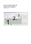
Control Center Series 30 User Manual
For CCS30 Version 1.1
Keller AG für Druckmesstechnik
St. Gallerstrasse 119
CH-8404 Winterthur
Index
1 Installation ..................................................................................................................... 4
1.1 Microsoft .Net 2.0..................................................................................................................4
2 General Functions ........................................................................................................... 5
2.1 Search for Devices.................................................................................................................5
2.1.1 Default Search ...................................................................................................................5
2.1.2 Advanced Search................................................................................................................6
2.2 Remove Device .....................................................................................................................6
3 Measuring ....................................................................................................................... 7
3.1 Current Measurement Values..................................................................................................8
3.1.1 Box View ...........................................................................................................................8
3.1.2 Tabular View......................................................................................................................9
3.2 Performing a “New Measurement” ........................................................................................ 10
3.2.1 Configuring a Measurement............................................................................................... 11
3.2.2 Measuring........................................................................................................................ 12
3.2.3 Saving / Loading / Adding measurements ........................................................................... 15
3.2.4 Exporting Measurements ................................................................................................... 15
4 Configuring Devices ...................................................................................................... 16
4.1 Configuring Individual Devices.............................................................................................. 17
4.2 Configuring Devices using General Bus Address 250 ............................................................... 18
4.3 Configuring Multiple Devices Simultaneously .......................................................................... 19
5 Program Settings .......................................................................................................... 20
5.1 General .............................................................................................................................. 20
5.2 Pressure Unit ...................................................................................................................... 21
5.3 Communication Port (Comport) Overview .............................................................................. 22
5.4 Parameters at Program Start ................................................................................................ 22
5.5 Login.................................................................................................................................. 22
October 2009
CCS30 Manual_en.doc
Page 2/22
Keller AG für Druckmesstechnik
St. Gallerstrasse 119
CH-8404 Winterthur
Quick Search
No.
1
2
3
4
5
6
Function
Search for device
Remove device
Configure device
Start new measurement
Display current measurements
Existing devices
October 2009
Page
5
6
15
7
8
-
CCS30 Manual_en.doc
Page 3/22
Keller AG für Druckmesstechnik
St. Gallerstrasse 119
CH-8404 Winterthur
1
Installation
Download the software using the Keller installer. The setup program now starts automatically.
Follow the setup instructions.
1.1 Microsoft .Net 2.0
At the start of installation you are asked to install the required Microsoft .NET 2.0 software, if it is not already present. The files that are needed are downloaded directly from Microsoft.
October 2009
CCS30 Manual_en.doc
Page 4/22
Keller AG für Druckmesstechnik
St. Gallerstrasse 119
CH-8404 Winterthur
2
General Functions
2.1 Search for Devices
The device address and other search parameters can be defined when searching for devices, whereby
the default search setting (Auto) is usually sufficient. The advanced search allows additional settings to
be made for the serial interface.
The device list is regenerated during the default search.
2.1.1 Default Search
The interface (Comport), baud rate and an address range can be specified for the default search.
If a value has been set to “auto”, the search is carried out using all possible variants.
If several Comports are available, they are searched through simultaneously.
The following settings can be made for the “Address” field:
Entry
Meaning
auto
The search is carried out using bus address 250. All devices that are connected to
the bus reply when this address is used. If communication takes place using the
“auto” setting (address 250), only one device may be connected to the bus.
1
Devices are searched for with an address of 1.
1-30
Devices are searched for with addresses of 1, 2, 3,... 29, 30
1, 5
Devices are searched for with addresses of 1 and 5.
1, 7-18, 241
Devices are searched for with addresses of 1, 7-18 and 241.
The progress for each Comport is shown in the status line during a search:
October 2009
CCS30 Manual_en.doc
Page 5/22
Keller AG für Druckmesstechnik
St. Gallerstrasse 119
CH-8404 Winterthur
2.1.2 Advanced Search
An advanced search can be carried out with modified Comport settings (parity bit/stop bit).
The advanced search is activated using “View” “Advanced”:
The default settings are: No parity bit (none) and 1 stop bit.
2.2 Remove Device
All selected devices are removed from the device list using the “Remove” button.
October 2009
CCS30 Manual_en.doc
Page 6/22
Keller AG für Druckmesstechnik
St. Gallerstrasse 119
CH-8404 Winterthur
3
Measuring
Two different measuring types are available.
“New Measurement” [1]: Measurements can be carried out with advanced measuring parameters (interval, data storage, etc.) using this option.
“Current Meas. Values” [2]: The current measurements for all connected devices are displayed.
October 2009
CCS30 Manual_en.doc
Page 7/22
Keller AG für Druckmesstechnik
St. Gallerstrasse 119
CH-8404 Winterthur
3.1 Current Measurement Values
This window provides a rapid overview of all connected devices and their measurement values. Two different views are available:
3.1.1 Box View
The box view is used for device monitoring. The individual boxes (devices) can be moved by dragging
them and grouping/arranging them as required.
Minimum and maximum limits can be set. As soon as these values are undershot or exceeded, the relevant channel is highlighted in a particular color. The min./max. values and the colors can be modified by
right-clicking on the channel ("Edit Colors").
Individual channels can also be hidden using this menu.
Note:
If a device is no longer visible on the user interface (e.g. it has been pushed out of the display area), the
device can be deactivated and activated again by right-clicking on the background. This puts the device
back into the visible area.
October 2009
CCS30 Manual_en.doc
Page 8/22
Keller AG für Druckmesstechnik
St. Gallerstrasse 119
CH-8404 Winterthur
3.1.2 Tabular View
This is where the current measurements (channels) are displayed and can be conveniently checked and
compared.
October 2009
CCS30 Manual_en.doc
Page 9/22
Keller AG für Druckmesstechnik
St. Gallerstrasse 119
CH-8404 Winterthur
3.2 Performing a “New Measurement”
The measurement display is divided into two different areas. On the left there is the control area for
starting, stopping and configuring the measurement, and on the right there is the data area for displaying the measurement data. Clicking on “Start” causes a new measurement to be performed with all available channels of the selected devices.
The control area on the left contains the name of the measurement, the current measurement values for
the individual channels, the measuring interval and the file in which the measurement data is stored. The
measured channels can be stored in the form of a graph or a table.
The measurement settings can be modified using the “Config. Measurement” button. The settings can
only be changed if measuring has been stopped beforehand.
October 2009
CCS30 Manual_en.doc
Page 10/22
Keller AG für Druckmesstechnik
St. Gallerstrasse 119
CH-8404 Winterthur
3.2.1 Configuring a Measurement
If you click on “Config. Measurement” the configuration screen is displayed:
General [1]
The measuring interval can be specified in milliseconds, seconds, minutes or hours.
The smallest read-out interval is device-dependent. With devices with a baud rate of 115,200 baud the
fastest readout speed is 3 ms/channel. If the interval is smaller than the read-out speed specified by the
device, the device is read out using the fastest possible speed.
Activating “Save Data” causes the measurement data to be saved continuously.
Attention: Many measurement values and large files
The CCS30 is extremely powerful, and it is easy to collect large quantities of data that are subsequently
difficult to process. Excel cannot handle more than 65000 measurements per channel. At a measuring
speed of 3ms with one channel, this quantity is reached in just 3 minutes and 15 seconds.
October 2009
CCS30 Manual_en.doc
Page 11/22
Keller AG für Druckmesstechnik
St. Gallerstrasse 119
CH-8404 Winterthur
Approximately 70kb of metadata is generated for each connected device. Each measurement requires 20
bytes of storage space. The file for the measurement with one transmitter with 65000 measurements is
1.37 MB in size.
Info [2]
The name of the measurement and the description can be entered as required.
Measuring channels [3]
All existing devices/channels that are not yet involved in measuring can be seen on the left-hand side.
The list on the right shows devices/channels that have been selected for the measurement. The devices/channels can be moved to the relevant side by dragging, double clicking or single clicking (followed
by “>>” or “<<”).
Measuring
Clicking on “<<Measure” takes you back to the original view.
3.2.2 Measuring
October 2009
CCS30 Manual_en.doc
Page 12/22
Keller AG für Druckmesstechnik
St. Gallerstrasse 119
CH-8404 Winterthur
The current measurements are displayed on the left during the measurement [1]. The relevant channels
are revealed or hidden in the graph by activating or deactivating the check boxes. The graphical display
[2] shows the channels as per the configuration. The channels can be individually scaled by clicking on
“Properties” [3]. Right-clicking on the graphs opens a pop-up menu [4] containing different options for
viewing/saving the graphs. The tabular view can be called up using the "Table" tab [5].
It can take a considerable time to update the graph if large quantities of data are involved. In this case a
message is displayed saying that the graph is no longer being automatically updated. Updating now
takes place using the “Update Values” button [6]. This function prevents re-drawing of the graph (which
may be time-intensive) from affecting the measuring interval.
In order to make it possible to compare channels to each other, the individual channels can be scaled
manually. These settings can also be changed during an active measurement.
Scale channels [1]
The gain and the offset can be modified for each channel.
October 2009
CCS30 Manual_en.doc
Page 13/22
Keller AG für Druckmesstechnik
St. Gallerstrasse 119
CH-8404 Winterthur
Scale graph [2]
- A minimum and a maximum can be specified for the Y-axes.
- The window width can be defined.
- The legend can be displayed.
- The description of the measurement can be displayed (this is useful if the graph is being stored as a
“Print Screen” image)
Tabular view of measurement data:
Since the measurements are not all made at exactly the same time, a time is also allocated for each
measurement. All time axes apart from one can be hidden in order to provide an organized display [1].
The table can be updated by clicking on “Update” or automatically when a new page is selected [2]. The
pages can be called up by directly entering the page number of using the “<< < > >>” buttons. Approximately 15,000 measurement values can be displayed per page of the table.
Note:
The graph can display a maximum of 5,000,000 measurements, after which it is deactivated and the
measurement values are only shown in a table.
October 2009
CCS30 Manual_en.doc
Page 14/22
Keller AG für Druckmesstechnik
St. Gallerstrasse 119
CH-8404 Winterthur
3.2.3 Saving / Loading / Adding measurements
The measurement values can be saved continuously during the measurement ( 3.2.1 Configuring a
Measurement) or at the end of the measurement using the “Measurement” “Save” menu.
An old measurement is also loaded using the “Measurement” “Load” menu.
Old measuring data can be added to the current measurement. This allows an old measurement to be
continued (“Measurement” “Add”).
3.2.4 Exporting Measurements
Measurements can be exported as CSV and subjected to further processing with Excel or a similar program. The export is carried out using the “Measurement” “csv-Export” menu.
October 2009
CCS30 Manual_en.doc
Page 15/22
Keller AG für Druckmesstechnik
St. Gallerstrasse 119
CH-8404 Winterthur
4
Configuring Devices
In order to configure a device, it is selected and the individual parameters are modified.
Several devices can also be configured simultaneously.
Select the required device(s) and then click on "Configure":
(Double clicking on the relevant device with the mouse also takes you to the configuration facility).
The configuration screen is divided into three areas:
1.
2.
3.
Device and unit selection
Information about the selected device
Configuration area
October 2009
CCS30 Manual_en.doc
Page 16/22
Keller AG für Druckmesstechnik
St. Gallerstrasse 119
CH-8404 Winterthur
4.1 Configuring Individual Devices
If an individual device is selected in the main window, it is automatically selected in the configuration
window (see figure above).
Modifying the parameters:
Tab
Zeroing / current values
Communication
Advanced
CH0
Analogue output
Switch output
October 2009
Parameter
The available measuring channels for the devices are listed and the current measurement is displayed.
Channels can be zeroed here.
Bus address
Different parameters are listed depending on the device.
If no parameters are available, this Tab is hidden.
Possible parameters:
- Temperature compensation
- User units
- Block/release pressure units
- Starting pressure unit of device
- Display resolution
Channel 0 configuration (with which calculation is possible)
Scaling of analogue output
Configuration of switch output
CCS30 Manual_en.doc
Page 17/22
Keller AG für Druckmesstechnik
St. Gallerstrasse 119
CH-8404 Winterthur
4.2 Configuring Devices using General Bus Address 250
If “Address 250” is selected under “Configuration” (instead of the serial number), the same configuration
can be written to several devices in sequence. Only one individual device may be connected to the bus
(to the interface) if this configuration type is used.
Procedure: First connect a master device and click on “Read out Master”. This specifies the available configuration parameters to the program.
Now modify parameters if necessary and click on “Write”. Remove configured device from the interface.
Then connect and describe the devices to be configured one after the other.
1.
2.
3.
4.
Select “Address 250”
Select Comport
Select baud rate
Read out master
October 2009
CCS30 Manual_en.doc
Page 18/22
Keller AG für Druckmesstechnik
St. Gallerstrasse 119
CH-8404 Winterthur
4.3 Configuring Multiple Devices Simultaneously
If multiple devices are being configured simultaneously, the devices that are connected to the same
Comport must have different addresses and the same baud rate.
This function makes it possible to perform simultaneous zeroing of multiple devices (within a few milliseconds), for example.
1.
2.
3.
Select “Multiple devices”
Select required devices
“Run” the configuration
If a configuration setting can only be made for one device (e.g. zeroing P2) it is only carried out for this
device. The remaining devices are unaffected.
October 2009
CCS30 Manual_en.doc
Page 19/22
Keller AG für Druckmesstechnik
St. Gallerstrasse 119
CH-8404 Winterthur
5
Program Settings
This is where general program settings are made that do not have a direct influence on the measuring
data or the device configurations.
5.1 General
Selecting the “Tools” “Settings” menu item takes you to the general program settings:
Load old Devices at Program Start:
The list of devices is empty when the program starts. If the devices that were being used when the program was lest exited are to be displayed, activate “Load old Devices at Program Start”.
“Delete old Devices at Search”
During a search for new devices the device list is cleared if "Delete old Devices at Search" is activated.
Scaling Steps:
The scaling steps define the resolution with which the measuring data is to be displayed.
Resolution = (PMax–PMin)/scaling steps
Language:
This is where the language is selected.
Log Level:
Important messages are stored in a log file. The number of entries is selected by adjusting the log level.
Comport-Timeout / TCP/IP-Timeout:
Specifies how long the CCS30 program waits for a reply from the device. Too small a value can lead to
missing measurements. We recommend the value shown above.
October 2009
CCS30 Manual_en.doc
Page 20/22
Keller AG für Druckmesstechnik
St. Gallerstrasse 119
CH-8404 Winterthur
5.2 Pressure Unit
The displayed pressure unit can be modified in different locations in the program. The measuring data is
always measured and saved in bar, but it is possible to change the display to a different unit.
The conversion factors and an offset can be set for a unit using the “Tools” “Units” menu option. The
unit can also be deactivated and therefore no longer appears for selection in the program. [1]
It is possible to add your own units [2].
October 2009
CCS30 Manual_en.doc
Page 21/22
Keller AG für Druckmesstechnik
St. Gallerstrasse 119
CH-8404 Winterthur
5.3 Communication Port (Comport) Overview
The Comport settings can be displayed via “Tools” “Comport overview”:
5.4 Parameters at Program Start
The Control Center can be started with parameters. The following parameters are possible:
Parameter
Meaning
[Measurement file name]
Automatically opens the specified file.
-run=[Measurement file
Automatically opens the specified file and continues the measurement.
name]
5.5 Login
The CCS30 program has other configuration options. This extension is enabled using “Tools” “Login”
followed by a password entry.
The password is: “prof”
October 2009
CCS30 Manual_en.doc
Page 22/22