1
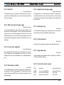
User Manual Laser Education Kit CA-1200 HeNe Laser c am pu s CA-1200 H e l i u m N e o n L a se r Contents CONTENTS 1 LASER SAFETY PRECAUTIONS ................................................................ 4 2 DESCRIPTION OF ELEMENTS.................................................................. 5 3 THE LASER TUBE SUPPLY LTS 1500 .......................................................... 7 3.1 General ...................................................................................................................................................................................................................................................................... 7 3.2 Front Panel Controls............................................................................................................................................................................................................................................... 8 3.2.1 Section Laser Power........................................................................................................................................................................................................................................... 8 3.2.2 Section Tube Current ........................................................................................................................................................................................................................................ 8 3.2.3 Section Photo Diode ........................................................................................................................................................................................................................................... 8 3.2.4 Section Laser Control ........................................................................................................................................................................................................................................ 8 3.3 Rear Panel Controls ................................................................................................................................................................................................................................................ 9 3.3.1 Mains connection and switch .......................................................................................................................................................................................................................... 10 3.3.2 Connector for photo diode ............................................................................................................................................................................................................................. 10 3.3.3 Laser tube connection ..................................................................................................................................................................................................................................... 10 4 THE LIGHT SOURCE CONTROLLER LSC 2000 ............................................... 11 4.1 General ..................................................................................................................................................................................................................................................................... 11 4.2 LSC 2000 Front Panel ........................................................................................................................................................................................................................................... 11 4.2.1 Section Line Power ............................................................................................................................................................................................................................................ 11 4.2.2 Section Light Source ........................................................................................................................................................................................................................................ 11 4.3 LSC 2000 Rear Panel ............................................................................................................................................................................................................................................. 11 4.3.1 Mains connector ................................................................................................................................................................................................................................................. 11 4.3.2 Laser head connection ...................................................................................................................................................................................................................................... 11 copyright © 2012 PI miCos GmbH Freiburger Straße 30 79427 Eschbach Germany - www.pimicos.com Page 2 c am pu s 5 C A - 1 20 0 H e l i u m N e o n L a se r Laser Safety ADJUSTMENT OF THE LASER ................................................................ 13 5.1 3.2 5.2 5.3 5.4 5.5 5.6 6 Definition of the optical axis ............................................................................................................................................................................................................................. 13 Pre-adjustment of the laser mirrors ............................................................................................................................................................................................................... 14 Adjustment of the main laser tube .................................................................................................................................................................................................................. 15 Get the main laser oscillation ............................................................................................................................................................................................................................ 16 Adjustment of the Littrow prism (full version) ............................................................................................................................................................................................ 17 Adjustment of the birefringent filter (full version) ................................................................................................................................................................................... 18 Adjustment of the Etalon (full version) .......................................................................................................................................................................................................... 19 MEASUREMENTS WITH THE LASER SYSTEM .............................................. 20 6.1 6.2 6.3 6.4 6.5 6.6 6.7 6.8 6.9 Output power versus laser tube current........................................................................................................................................................................................................ 20 Optical stability area of the resonator .......................................................................................................................................................................................................... 20 Beam diameters inside the resonator ............................................................................................................................................................................................................. 20 Output power versus laser tube position ........................................................................................................................................................................................................ 21 Mode structures ................................................................................................................................................................................................................................................... 21 Single mode operation with etalon (full version) .......................................................................................................................................................................................... 21 Wavelength selection with birefringent filter (full version) ..................................................................................................................................................................... 21 Wavelength selection with Littrow prism (full version) .............................................................................................................................................................................. 21 Infrared wavelength operation (optional) ....................................................................................................................................................................................................... 21 7 RECOMMENDED LITERATURES ............................................................... 22 8 PHOTO DIODE DATA SHEET.................................................................. 23 copyright © 2012 PI miCos GmbH Freiburger Straße 30 79427 Eschbach Germany - www.pimicos.com Page 3 c am pu s C A - 1 20 0 H e l i u m N e o n L a se r Laser Safety 1 Laser Safety Precautions The delivered laser system as well as the adjustment laser (part 6) are classified according to DIN IEC 60825-1 as a The following sign posts must be installed marked visible close to the system: Class 2 Laser in the basic version without output coupler mirror If additional optics like output mirrors, other mirrors, prisms or filters are used like in the full version of this system it is classified according to DIN IEC 60825-1 as a Class 3B Laser in the full version It is recommended to use the appropriate laser safety goggles in addition with protective sides against laser stray light caused by additional optics during the measurements. OR The carryout of the measurements with the system may be done only by adequate instructed people. copyright © 2012 PI miCos GmbH Freiburger Straße 30 79427 Eschbach Germany - www.pimicos.com Page 4 c am pu s 2 C A - 1 20 0 H e l i u m N e o n L a se r Description Description of elements copyright © 2012 PI miCos GmbH Freiburger Straße 30 79427 Eschbach Germany - www.pimicos.com Page 5 c am pu s C A - 1 20 0 H e l i u m N e o n L a se r Part 1 Profile Rail Description Part 6: Alignment laser with power supply (basic and full version) (basic and full version) The complete set-up will be mounted on a 1000 mm optical rail which is reinforced by an additional profile rail to increase the mechanical stability of the laser resonator. The alignment laser is a 1 mW HeNe laser in holders. Its output beam is centred to the mechanical centre of its housing. The laser is used to define the optical axis of the system. All further alignments of the educational kit base on this axis. Part 2: HeNe-Laser Tube with power supply (basic and full version) The used special HeNe-Laser tube has Brewster angle windows at both ends mounted. This makes possible to set-up a HeNe laser with external resonator mirrors for educational purposes. The tube itself is built in two XY-adjustment holders on a carrier base. The power supply for the tube is firmly connected and supplies the tube with its nominal values for current and voltage. Part 7: Birefringent tuner (full version) A disc of natural birefringent quartz is mounted in an rotator unit which allows the tuning of different wavelength in the laser system. Part 8: Littrow prism tuner (full version) A high quality ‘Littrow’ prism is provided for laser wavelength selection. Part 3+4: Laser mirror adjustment (basic and full version) These components hold the resonator mirrors and give the user the possibility to adjust them in the perpendicular axes. The mirror can be exchanged very easily to meet the demands for the corresponding measurement Part 5: Photo detector in holder (full version) The used PIN-photodiode is mounted in a housing with a BNC-socket for the connection to the photo diode amplifier. The connection will be done with the help of a provided BNC cable to the amplifier included in the laser tube power supply. copyright © 2012 PI miCos GmbH Freiburger Straße 30 79427 Eschbach Germany - www.pimicos.com Part 9: Single mode etalon (full version) Single mode Etalon with adjustment holder. The Etalon has a diameter of 12,7 mm and a thickness of 10 mm. Part 10: Set of laser mirrors in mount PLAN plane mirror (basic and full version) FL1000 FL700 OC24 mirror curvature 1000 mm mirror curvature 700 mm plane mirror output 2.4 % (basic and full version) (full version) (full version) Page 6 c am pu s C A - 1 20 0 H e l i u m N e o n L a se r Laser Tube Supply LTS 1500 3 The Laser Tube Supply LTS 1500 3.1 General The enclosure of the controller LTS 1500 can be tilted with the help of two hinged feet at its bottom. The air vents at the top and the bottom of the enclosure may not be covered. A sufficient free air circulation is ensured if there is a free space of 100 mm all around the enclosure. Opening the enclosure may be done disconnected from mains by authorized people only. copyright © 2012 PI miCos GmbH Freiburger Straße 30 79427 Eschbach Germany - www.pimicos.com Page 7 c am pu s C A - 1 20 0 H e l i u m N e o n L a se r Laser Tube Supply LTS 1500 3.2 Front Panel Controls 3.2.1 Section Laser Power 3.2.3 Section Photo Diode The key switch at this section is allows only permitted people to get the laser started. This key fulfills the standard DIN EN 60825-1. The push buttons () at this section set the gain of photo diode amplifier. The photo diode (part 5) must be connected at the BNC socket at the rear panel of the controller. The gain of the amplifier is indicated by a LED bar. The shown value at the display corresponds to the relative output power of the laser and can be used as an aid to get an optimized adjustment of the laser. 3.2.2 Section Tube Current With the push buttons () at this section the tube current can be set in steps of 0.1 mA. The actual tube current is shown at the display in mA. 3.2.4 Section Laser Control This section is for future use. copyright © 2012 PI miCos GmbH Freiburger Straße 30 79427 Eschbach Germany - www.pimicos.com Page 8 c am pu s C A - 1 20 0 H e l i u m N e o n L a se r Laser Tube Supply LTS 1500 3.3 Rear Panel Controls copyright © 2012 PI miCos GmbH Freiburger Straße 30 79427 Eschbach Germany - www.pimicos.com Page 9 c am pu s C A - 1 20 0 H e l i u m N e o n L a se r Laser Tube Supply LTS 1500 3.3.1 Mains connection and switch Before the controller is connected to the line voltage it must be checked if the voltage specification at the nameplate at its rear panel is identical. Make the mains connection with the provided mains cable and insure a proper junction. The value of the fuse in the power connector is 0.5 amps. A spare fuse is delivered with the controller. 3.3.2 Connector for photo diode The Photo detector (Part 5 within full version) has to be connected to BNC socket the rear panel with the delivered BNC-cable 3.3.3 Laser tube connection The high voltage power supply is connected via a high voltage cable to the laser tube. The cable is sensitive in bending with small radius. Ensure a tension free guiding and don’t pull the cable. copyright © 2012 PI miCos GmbH Freiburger Straße 30 79427 Eschbach Germany - www.pimicos.com Page 10 c am pu s C A - 1 20 0 H e l i u m N e o n L a se r Adjustment of the laser 4 The Light Source Controller LSC 2000 4.1 General The enclosure of the controller LTS 1500 can be tilted with the help of two hinged feet at its bottom. The air vents at the top and the bottom of the enclosure may not be covered. A sufficient free air circulation is ensured if there is a free space of 100 mm all around the enclosure. Opening the enclosure may be done disconnected from mains by authorized people only. 4.2 4.2.1 LSC 2000 Front Panel Section Line Power A green LED indicates whether the mains power is switched on by the mains switch at the rear panel of the power supply LSC 2000. If the mains power is switched on, the light sources are ready for ignition. 4.2.2 Section Light Source 4.3 4.3.1 LSC 2000 Rear Panel Mains connector Before the power supply LSC 2000 is connected to the line voltage it has to be checked whether the line voltage matches the voltage indicated at the label at the rear panel. To insure a proper junction the provided mains cable has to be used. The value of the fuse in the power connector is 0,315 amps. Using a key switch the ability is given to only let an authorized person operate the laser. This key fulfills the standard DIN EN 60825-1. 4.3.2 Turning the key, the DPSS laser is emitting green light of 532 nm wavelength. The power supply is rigidly coupled with the laser head by a power cable. Ensure a tension free guiding and don’t pull on the cable! copyright © 2012 PI miCos GmbH Freiburger Straße 30 79427 Eschbach Germany - www.pimicos.com Laser head connection Page 11 c am pu s C A - 1 20 0 H e l i u m N e o n L a se r Adjustment of the laser Caution: Dangerous laser emission may appear when installing or operating the laser system! Therefore it is necessary to arrange safety precautions and to follow the appropriate laser safety instructions! copyright © 2012 PI miCos GmbH Freiburger Straße 30 79427 Eschbach Germany - www.pimicos.com Page 12 c am pu s C A - 1 20 0 H e l i u m N e o n L a se r Adjustment of the laser 5 Adjustment of the laser 5.1 Definition of the optical axis The very first job which must be done is the definition of the optical axis of the laser system. For this purpose place the holder 5 with the target screen insert (remove the photo detector) and the alignment laser 6, on the optical rail 1 like shown in the draft above. Switch on the adjustment laser and check if the laser beam hit roughly the center of the target insert 5. Small corrections can be done by turning the housing of the adjustment laser in its holders. Once the laser is adjusted, the optical axis is defined and no further movement of the laser should be done while proceeding the following adjustment steps! copyright © 2012 PI miCos GmbH Freiburger Straße 30 79427 Eschbach Germany - www.pimicos.com Page 13 c am pu s 3.2 C A - 1 20 0 H e l i u m N e o n L a se r Adjustment of the laser Pre-adjustment of the laser mirrors The laser mirror adjustment holder 4 is placed on the optical rail as shown in the draft above. Insure that the well cleaned plane laser mirror marked with PLAN is mounted in the holder. The laser mirror has to be adjusted with the adjustments screw in that way that the back reflected beam of the adjustment laser hits itself exactly at its beam output aperture. The perfect alignment to the defined optical axis can be recognized by observing a flickering laser beam caused by interference effects with the plane mirror in the holder. copyright © 2012 PI miCos GmbH Freiburger Straße 30 79427 Eschbach Germany - www.pimicos.com The procedures for the other laser mirror adjustment holder 3 are similar. Use the laser mirror marked with FL1000, clean it and screw it into the adjustment holder. Place the holder in a 180° flipped position (mirror surface points to the adjustment laser, elimination of wedge effects) around 500 mm in front of the adjustment laser like shown in the sketch above. Due to the curvature of this laser mirror (1000 mm) the observed interference effects are more divergent. Adjust the beams centered around the output aperture of the adjustment laser. If the alignment is finished remove both adjustment holders from the optical rail and place it beside. Page 14 c am pu s C A - 1 20 0 H e l i u m N e o n L a se r Adjustment of the laser 5.2 Adjustment of the main laser tube The next step is the adjustment of the main laser 2. Adjust the tube roughly to the center of its holders with the help of the X/Y adjustment screws and put it on the rail like shown in the figure above. Be sure that the Brewster windows of the main laser 2 are well cleaned and its power supply is switched off. The goal is to adjust the main lasers capillary around the optical axis of the adjustment laser with the X/Y adjustment screws. The actual position can be observed at a reflective screen like a piece of white paper or a white copyright © 2012 PI miCos GmbH Freiburger Straße 30 79427 Eschbach Germany - www.pimicos.com wall. Best results are achieved if the distance of the screen is more than one meter. Some sample results are shown in the drawing above. The system must be aligned until the beam of the adjustment laser is perfectly centered without any reflections at the main tube. This is absolutely necessary for all further adjustments. The better the adjustment is done, the easier you get the very first oscillation of the laser. Page 15 c am pu s C A - 1 20 0 H e l i u m N e o n L a se r Adjustment of the laser 5.3 Get the main laser oscillation Finally to get the laser light arrange the pre-adjusted components 2,3 & 4 like shown in the sketch above. Inspect again the surfaces of the Brewster windows of the main laser 2 and of the laser mirrors 3 & 4 if there are no contamination like dust or fingerprints. Switch off the adjustment laser 6 and switch on the main laser tube 2 with the key switch at the controller LTS 1500. If all the previous adjustments are done excellent the main laser starts immediately. If no laser light can be observed, a gentle twisting of max. +/- 45° of one of the adjustment screws shown in the draft above cause the oscillation flickcopyright © 2012 PI miCos GmbH Freiburger Straße 30 79427 Eschbach Germany - www.pimicos.com er up. This can be observed at the surface of one of the laser mirrors 3 or 4. If this alignment fails return the screw to the start position and twist the other one. If you get the laser oscillation the output power can be optimized with the position of the laser mirrors 3 & 4 and supplementary with the X/Y adjustments of the main tube 2. If still no laser oscillation can be observed, start again from the beginning and check if the correct laser mirrors are mounted and if all the optics are clean. Page 16 c am pu s C A - 1 20 0 5.4 Adjustment of the Littrow prism H e l i u m N e o n L a se r Adjustment of wavelength selectors (full version) After the basic adjustment of the main laser and achieved optimized laser operation, carefully remove the components 2, 3 & 4 from the optical rail and avoid misalignment of them. Place the adjustment holder with the Littrow prism 8 onto the rail like shown in the left figure above. Switch on the adjustment laser 6 and align the reflection of the Littrow prism like it was done while adjusting the laser mirrors. copyright © 2012 PI miCos GmbH Freiburger Straße 30 79427 Eschbach Germany - www.pimicos.com Now the parts 2 & 3 can be assembled again. Switch off the adjustment laser 6 and switch on the main laser 2. If the laser oscillation doesn’t start again continue with the wobbeling procedures of component 3 a & b as mentioned in the chapter of the adjustment of the main laser oscillation before. These alignments are much more sensitive than the ones before and should be carried out very careful. The cleaning of the optics is tremendously important. If the laser starts oscillating, optimize it for very best intensity. The laser line tuning can be done with the adjustment screws c & d of the component 8. Page 17 c am pu s 5.5 C A - 1 20 0 Adjustment of the birefringent filter H e l i u m N e o n L a se r Adjustment of wavelength selectors (full version) Rotate the insert of part 8 to the Brewster’s angle and configure the setup as shown in the left draft above. Repeat the alignment of the laser mirror in part 4 to eliminate the beam displacement of the inserted optic. If finished, the setup can be completed again like in the right figure above. Another way is to insert the birefringent filter directly into the working laser resonator. For this purpose align the resonator for best laser output and insert the part rotated perpendicular to the laser beam. Rotate the BFP around its optical axis until the laser starts again. Optimize the laser again. Next step is turning the plate itself to the Brewster’s angle in several steps with realigning the laser in between. If the Brester’s angle is achieved the laser output power increases noticeable. If the BFP is rotated around it optical axis you can see the main line 632.8 nm up to 4 times. The strongest one should be chosen and the laser should be optimized again. copyright © 2012 PI miCos GmbH Freiburger Straße 30 79427 Eschbach Germany - www.pimicos.com If the birefringent filter is rotated in small angles around chosen main line you can get 4 additional wavelengths with different gains according to the table below: No. Wavelength Gain 1. 611.8 nm 10 2. 629.8 nm 20 3. 632.8 nm 100 4. 635.2 nm 6 5. 640.1 nm 34 The line no. 1 at 611.8 nm and the line no. 4 at 635.2 nm are very sensitive to pollution on the optics. To get these lines it is very important to clean the optics and the Brewster windows of the laser tube very carefully. Once the orange line is oscillating realign the laser and optimize the Brewster’s angle of the BFP. The weak lines can disappear and appear again by turning the birefringent filter plate. Page 18 c am pu s C A - 1 20 0 5.6 Adjustment of the Etalon H e l i u m N e o n L a se r Adjustment of the Etalon (full version) The part 9 with the single mode etalon will be placed on the rail instead of the BFP 8 after it has been adjusted with the screws in its holder to be roughly perpendicular to the optical axis of the laser. If put into the resonator the laser normally keeps its oscillation more or less strong. If the back reflections at the mirror surface of component 3 are observed you can identify a non perpendicular adjustment with several spots. copyright © 2012 PI miCos GmbH Freiburger Straße 30 79427 Eschbach Germany - www.pimicos.com The zero order adjustment is achieved if all reflections fall into the beam of the main laser. Other orders can be adjusted by tilting one of the adjustment screws of the etalon holder 9. To check out if the laser is running in single mode, an external fabry perot interferometer is necessary. Page 19 c am pu s C A - 1 20 0 H e l i u m N e o n L a se r 6 Measurements with the laser system With Laser system CA-1200 the following measurements can be done: Output power dependence on laser tube current Optical stability area of the resonator Beam diameters inside the resonator Output power dependence on laser tube position Furthermore mode behavior of the laser itself and in combination with an etalon will be investigated. The reactions of the use wavelength influencing elements like filter and prism inside the laser resonator will be shown. 6.1 Output power versus laser tube current For this measurement the basic alignment according up to chapter 5.3 must be done and the main laser should be in well optimized laser oscillation. The used mirror pair can be the FLAT & FL1000 or the other pair consisting of FLAT & FL700. Within this measurement a diagram is taken. The x-axis is plotted with steps of the tube current in milliamps varied from 5.0 to 6.5 by the keys. The values for the y-axis are read from relative output power display of the photo amplifier. Please note: The gain of the photo diode amplifier should be set to a value where no saturation of the amplifier can occur. It can be easily checked by varying the gain with following variation of the tube current range. If the output coupler mirror is used the fluorescence light of the laser tube becomes influence to measurement. For this case two measures should be subtracted, one with laser operation and the other one without. (laser operation can be interrupted by putting a piece of paper in front of the right laser mirror. LDS 1200 6.2 Optical stability area of the resonator As well as the while the measurement before the adjustment of the laser according up to chapter 5.3 must be carried out. The measurement of the area of resonator stability itself can be done with both mirror sets (FLAT & FL1000 or FLAT & FL700). For this purpose the spherical mirror, normally part 3 is shifted on the optical rail away from the discharge tube step by step after the lock screw of the carrier with the mirror is slightly loosened. After every small step the laser should be realigned to maximum output. If the stability limit is obtained the laser stop its laser oscillation and it is not possible to get laser light. The found distance can be read out from the scale stuck on the optical rail. The obtained value corresponds with the value of the laser mirror curvature. The same procedures for the set up of the photo diode amplifier as in 6.1 should be carried out. The results can be compared with the stability criterion of an optical resonator in dependence of the resonator mirror curvature in the theory. 6.3 Beam diameters inside the resonator The measurement of the beam diameters inside the resonator in dependence of the curvatures of the used laser mirrors can be done by a caliper square. To get the values the measure of the caliper square is made smaller and held into the resonator. If the distance becomes too small no laser oscillation is seen. The same procedure can be done several times inside the resonator until sufficient measurement points are obtained to draw a profile of the internal beam divergence. To receive a full profile the measurements should be done on both sides of the laser tube between mirror and Brewster window of the tube. Please note: The Brewster windows of the laser tube are very sensitive on hits and scratching. Be careful while these measurements are carried out. Rem.: The influence of the tube current to the output power is very weak. copyright © 2012 PI miCos GmbH Freiburger Straße 30 79427 Eschbach Germany - www.pimicos.com Page 20 c am pu s C A - 1 20 0 H e l i u m N e o n L a se r LDS 1200 6.4 Output power versus laser tube position 6.6 Single mode operation with etalon Within this measurement the mechanical position of the laser discharge tube is varied and plotted at the x-axis of a diagram. The relative output power is taken from the display and plotted at the y-axis. Follow the remarks and descriptions in Chapter 5.6 For this measurement both mirror sets, one after an other, can be used. The alignment of the resonator should be set to its stability minimum depending of the used mirror set (FLAT & FL1000 or FLAT & FL700). After every new mechanical position of the tube, the laser should be optimized again in its out put power until the power value is taken. As a result the variation of output power depending on the used mirror curvatures related to the beam diameters is recognized and can be discussed afterwards. Please note: The laser must be adjusted according up to chapter 5.3. The same procedures for the set up of the photo diode amplifier as in chapter 6.1 mentioned should be carried out. (Part 5 photo detector only available in full version) 6.5 Mode structures This experiment should be carried out by using a spherical resonator setup. Viewing transversal laser modes can be achieved with the help of a lens with a focal length of appr. 40 mm depending on the distance of a display screen to visualize the mode pattern. The modes can be produced if one resonator mirror will be something misaligned. Higher modes are recognized by a intensity distribution with areas where the light intensity converges to zero. If no structures can be obtained by a trick. Insert a so called optical short circuit into the laser beam, a very thin wire or a human hair will give good results, and the distribution of laser light which look like higher laser modes become visible. copyright © 2012 PI miCos GmbH Freiburger Straße 30 79427 Eschbach Germany - www.pimicos.com (full version) 6.7 Wavelength selection with birefringent filter (full version) Follow the remarks and descriptions in chapter 5.5 Please note: For this experiments absolutely clean optical surfaces are unconditional necessary. The alignment must be done very accurate and experienced. 6.8 Wavelength selection with Littrow prism (full version) Follow the remarks and descriptions in chapter 5.4 Please note: For this experiments absolutely clean optical surfaces are unconditional necessary. The alignment must be done very accurate and experienced. 6.9 Infrared wavelength operation (optional) This feature is optional available (CA-1205) to the educational kit. The set consists of two laser mirror which are coated for infrared operation of the laser. The adjustments are similar to adjustments for the visible operation. Better results are achieved if the adjustments are done in room with subdued light. In this case the optical effects of the adjustments in chapter 3.2 are visible much more better. Even the results for starting up the laser oscillation are easier. All measurements mentioned before can also be done with infrared configuration. The Littrow prism is not useable due to its optical coating. The results of the use of the birefringent filter can be preferably observed with a monochromator. Page 21 c am pu s 7 C A - 1 20 0 H e l i u m N e o n L a se r Literatures Recommended literatures in german language: in english language: Wulfhard Lange Einführung in die Laserphysik Wissenschaftliche Buchgesellschaft Darmstadt 1983 O. Svelto Principles of Lasers Plenum Press, New York, 1989 Bergmann / Schaefer. Lehrbuch der Experimentalphysik, Band 3: Optik. de Gruyter, 1993 Weber / Herziger. Laser, Grundlagen und Anwendungen. Physik Verlag, 1972 Kleen / Müller. Laser. Springer-Verlag, 1969 F. K. Kneubühl und M. W. Sigrist Laser Teubner, Stuttgart 1988 copyright © 2012 PI miCos GmbH Freiburger Straße 30 79427 Eschbach Germany - www.pimicos.com A. E. Siegmann Lasers University Press, Oxford 1986 P. W. Milonni und J. H. Eberly Lasers John Wiley, New York 1988 J. Hecht: The Laser Guidebook McGraw-Hill Inc., New York 1992 A. Yariv Quantum Electronics John Wiley, New York 1975 Page 22 8 Photo Diode Data Sheet BPX 61 Silizium-PIN-Fotodiode Silicon PIN Photodiode BPX 61 Features Especially suitable for applications from 400 nm to 1100 nm Short switching time (typ. 20 ns) Hermetically sealed metal package (similar to TO-5) Anwendungen Lichtschranken f Ÿr Gleich- und Wechsellichtbetrieb IR-Fernsteuerungen Industrieelektronik ÒMessen/Steuern/Regeln Ó Typ Type Bestellnummer Ordering Code BPX 61 Q62702-P25 Semiconductor Group Application Photointerrupters IR-remote controls Industrial electronics For control and drive circuits 357 Grenzwerte Maximum Ratings Bezeichnung Description Symbol Symbol W ert Value Einheit Unit Betriebs- und Lagertemperatur Operating and storage temperature range Top; Tstg Ð 40 ... + 125 C Lšttemperatur (L štstelle 2 mm vom GehŠuse entfernt bei L štzeit t 3 s) Soldering temperature in 2 mm distance from case bottom ( t 3 s) TS 230 C Sperrspannung Reverse voltage VR 32 V Verlustleistung, TA = 25 C Total power dissipation Ptot 250 mW Kennwerte (TA = 25 C, Normlicht A, T = 2856 K) Characteristics (TA = 25 C, standard light A, T = 2856 K) Ma§e in mm, wenn nicht anders angegeben/Dimensions in mm, unless otherwise specified. W esentliche Merkmale Speziell geeignet f Ÿr Anwendungen im Bereich von 400 nm bis 1100 nm Kurze Schaltzeit (typ. 20 ns) Hermetisch dichte Metallbauform (Šhnlich TO-5) BPX 61 10.95 Bezeichnung Description Symbol Symbol W ert Value Einheit Unit Fotoempfindlichkeit, VR = 5 V Spectral sensitivity S 70 ( 50) nA/Ix Wellenl Šnge der max. Fotoempfindlichkeit Wavelength of max. sensitivity S max 850 nm Spektraler Bereich der Fotoempfindlichkeit S = 10 % von Smax Spectral range of sensitivity S = 10 % of Smax 400 ... 1100 nm Bestrahlungsempfindliche Fl Šche Radiant sensitive area A 7.00 mm 2 Abmessung der bestrahlungsempfindlichen FlŠche Dimensions of radiant sensitive area LB 2.65 2.65 mm Abstand Chipoberfl Šche zu Geh ŠuseoberflŠche Distance chip front to case surface H 1.9 ... 2.3 mm Halbwinkel Half angle 55 Grad deg. Dunkelstrom, VR = 10 V Dark current IR 2 ( 30) nA Semiconductor Group 358 LW Version 1/12