1
bdi GDB
BDM interface for GNU Debugger
PowerPC MPC8xx/MPC5xx
User Manual
Manual Version 1.16 for BDI2000
©1997-2001 by Abatron AG
bdiGDB for GNU Debugger, BDI2000 (MPC8xx/MPC5xx)
User Manual
2
1 Introduction ................................................................................................................................. 3
1.1 BDI2000................................................................................................................................. 3
1.2 BDI Configuration .................................................................................................................. 4
2 Installation ................................................................................................................................... 5
2.1 Connecting the BDI2000 to Target......................................................................................... 5
2.1.1 Changing Target Processor Type ................................................................................. 7
2.2 Connecting the BDI2000 to Power Supply............................................................................. 8
2.2.1 External Power Supply ................................................................................................. 8
2.2.2 Power Supply from Target System ............................................................................... 9
2.3 Status LED «MODE»........................................................................................................... 10
2.4 Connecting the BDI2000 to Host ......................................................................................... 11
2.4.1 Serial line communication .......................................................................................... 11
2.4.2 Ethernet communication ............................................................................................ 12
2.5 Installation of the Configuration Software ............................................................................ 13
2.6 Initial configuration of the bdiGDB system........................................................................... 13
2.7 Testing the BDI2000 to host connection .............................................................................. 14
2.8 TFTP server for Windows NT............................................................................................... 14
3 Using bdiGDB ............................................................................................................................ 15
3.1 Principle of operation........................................................................................................... 15
3.2 Configuration File ................................................................................................................ 17
3.2.1 Part [INIT]................................................................................................................... 17
3.2.2 Part [TARGET] ........................................................................................................... 19
3.2.3 Part [HOST]................................................................................................................ 21
3.2.4 Part [FLASH] .............................................................................................................. 22
3.2.5 Part [REGS] ............................................................................................................... 26
3.3 Debugging with GDB ........................................................................................................... 28
3.3.1 Target setup................................................................................................................ 28
3.3.2 Connecting to the target............................................................................................. 28
3.3.3 Breakpoint Handling................................................................................................... 28
3.3.4 Embedded Linux MMU Support................................................................................. 29
3.3.5 PPC Interrupt Handling .............................................................................................. 30
3.4 Telnet Interface .................................................................................................................... 31
4 Specifications ............................................................................................................................ 33
5 Environmental notice ................................................................................................................ 34
6 Declaration of Conformity (CE) ................................................................................................ 34
7 Warranty ..................................................................................................................................... 35
Appendices
A BDI2000 Setup/Update ............................................................................................................. 36
B Troubleshooting ........................................................................................................................ 38
C Maintenance .............................................................................................................................. 39
D Trademarks ................................................................................................................................ 41
© Copyright 1997-2001 by ABATRON AG Switzerland
V 1.16
bdiGDB for GNU Debugger, BDI2000 (MPC8xx/MPC5xx)
User Manual
3
1 Introduction
bdiGDB enhances the GNU debugger (GDB), with Background Debug Mode (BDM) debugging for
MPC8xx/MPC5xx based targets. With the built-in Ethernet interface you get a very fast code download speed of up to 150Kbytes/sec. No target communication channel (e.g. serial line) is wasted for
debugging purposes. Even better, you can use fast Ethernet debugging with target systems without
network capability. The host to BDI communication uses the standard GDB remote protocol.
An additional Telnet interface is available for special debug tasks (e.g. force a hardware reset,
program flash memory).
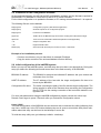
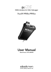
The following figure shows how the BDI2000 interface is connected between the host and the target:
Target System
MPC
8xx
BDM Interface
BDI2000
UNIX / PC Host
GNU Debugger
(GDB)
Abatron AG
Swiss Made
Ethernet (10 BASE-T)
1.1 BDI2000
The BDI2000 is the main part of the bdiGDB system. This small box implements the interface between the BDM pins of the target CPU and a 10Base-T Ethernet connector. BDI2000 is powered by
a MC68360, 512Kbyte RAM and a flash memory of 1024Kbyte. As a result of consistent implementation of lasted technology, the BDI2000 is optimally prepared for further enhancements. The firmware and the programmable logic of the BDI2000 can be updated by the user with a simple Windows
based configuration program. The BDI2000 supports 5 Volts and 3.3 Volts target systems.
© Copyright 1997-2001 by ABATRON AG Switzerland
V 1.16
bdiGDB for GNU Debugger, BDI2000 (MPC8xx/MPC5xx)
User Manual
4
1.2 BDI Configuration
As an initial setup, the IP address of the BDI2000, the IP address of the host with the configuration
file and the name of the configuration file is stored within the flash of the BDI2000.
Every time the BDI2000 is powered on, it reads the configuration file via TFTP.
Following an example of a typical configuration file:
; bdiGDB configuration file for MPC860ADS board
; ---------------------------------------------;
[INIT]
; init core register
WSPR
638
0x02200000
;IMMR : internal memory at 0x02200000
WSPR
158
0x00000007
;ICTRL:
; init SIU register
WM32
0x02200000
0x01632440
;SIUMCR
WM32
0x02200004
0xFFFFFF88
;SYPCR
WM16
0x02200200
0x0002
;TBSCR
WM16
0x02200220
0x0102
;RTCSC
WM16
0x02200240
0x0002
;PTSCR
; init UPM
SUPM
0x02200168
0x0220017c
;set address for MCR and MDR
WUPM
0x00000000
0x8FFFEC24
;UPMA single read
WUPM
0x00000001
0x0FFFEC04
WUPM
0x00000002
0x0CFFEC04
WUPM
0x00000003
0x00FFEC04
..........
WUPM
0x0000003C
0x33FFCC07
WUPM
0x0000003D
0xFFFFFFFF
WUPM
0x0000003E
0xFFFFFFFF
WUPM
0x0000003F
0xFFFFFFFF
; init memory controller
WM32
0x02200104
0xFFE00D34
WM32
0x0220010C
0xFFFF8110
WM32
0x02200114
0xFFC00800
WM32
0x02200100
0x02800001
WM32
0x02200108
0x02100001
WM32
0x02200110
0x00000081
WM16
0x0220017A
0x0400
WM32
0x02200170
0x13A01114
;UPMA exception
;OR0 : 2MB, all accesses, 6ws, time relax
;OR1
;OR2
;BR0
;BR1
;BR2
;MPTPR : divide by 16
;MAMR
[TARGET]
CPUCLOCK
BDIMODE
BREAKMODE
25000000
AGENT
SOFT
[HOST]
IP
FILE
FORMAT
LOAD
DEBUGPORT
START
151.120.25.114
C:\cygnus\b19\demo\mpc860\vxworks
ELF
MANUAL
;load code MANUAL or AUTO after reset
2001
0x10000
;the CPU clock rate after processing the init list
;the BDI working mode (LOADONLY | AGENT | GATEWAY)
;<AGENT> SOFT or HARD, HARD uses PPC hardware breakpoints
Based on the information in the configuration file, the target is automatically initialized after every reset.
© Copyright 1997-2001 by ABATRON AG Switzerland
V 1.16
bdiGDB for GNU Debugger, BDI2000 (MPC8xx/MPC5xx)
User Manual
5
2 Installation
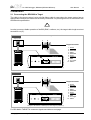
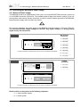
2.1 Connecting the BDI2000 to Target
The cable to the target system is a ten pin flat ribbon cable. In case where the target system has an
appropriate connector, the cable can be directly connected. The pin assignment is in accordance with
the Motorola specification.
!
In order to ensure reliable operation of the BDI (EMC, runtimes, etc.) the target cable length must not
exceed 20 cm (8").
Version A
«Version A» is the first BDI2000 version, produced until June 1999
Target System
9
1
MPC
8xx
Target Connector
2
10
BDI2000
BDI
Abatron AG
TRGT MODE
BDI MAIN
9
1
10
2
BDI OPTION
1 - VFLS0
2 - SRESET
3 - GROUND
4 - DSCK
5 - GROUND
6 - VFLS1
7 - HRESET
8 - DSDI
9 - Vcc Target
10 - DSDO
Swiss Made
The green LED «TRGT» marked light up when target is powered up
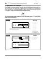
Version B
Target System
9
1
MPC
8xx
Target Connector
2
10
BDI2000
BDI
Abatron AG
TRGT MODE
TARGET A
9
1
10
2
TARGET B
1 - VFLS0
2 - SRESET
3 - GROUND
4 - DSCK
5 - GROUND
6 - VFLS1
7 - HRESET
8 - DSDI
9 - Vcc Target
10 - DSDO
Swiss Made
The green LED «TRGT» marked light up when target is powered up
For BDI MAIN / TARGET A connector signals see table on next page.
© Copyright 1997-2001 by ABATRON AG Switzerland
V 1.16
bdiGDB for GNU Debugger, BDI2000 (MPC8xx/MPC5xx)
User Manual
6
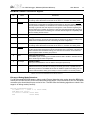
BDI MAIN / TARGET A Connector Signals:
Pin
Name
Describtion
1
VFLS0
These pin and pin 6 (VFLS1) indicate to the debug port controller whether or not the MPC
is in debug mode. When both VFLS0 and VFLS1 are at "1", the MPC is in debug mode.
2
SRESET
This is the Soft-Reset bidirectional signal of the MPC8xx. On the MPC5xx it is an output.
The debug port configuration is sampled and determined on the rising-edge of SRESET
(for both processor families). On the MPC8xx it is a bidirectional signal which may be driven
externally to generate soft reset sequence. This signal is in fact redundant regarding the
MPC8xx debug port controller since there is a soft-reset signal integrated within the debug
port protocol. However, the local debug port controller uses this signal for compatibility with
MPC5xx existing boards and s/w.
3+5
GND
System Ground
4
DSCK
Debug-port Serial Clock
During asynchronous clock mode, the serial data is clocked into the MPC according to the
DSCK clock. The DSCK serves also a role during soft-reset configuration.
6
VFLS1
These pin and pin 1 (VFLS0) indicate to the debug port controller whether or not the MPC
is in debug mode. When both VFLS0 and VFLS1 are at "1", the MPC is in debug mode.
7
HRESET
This is the Hard-Reset bidirectional signal of the MPC. When this signal is asserted (low)
the MPC enters hard reset sequence which include hard reset configuration. This signal is
made redundant with the MPC8xx debug port controller since there is a hard-reset command integrated within the debug port protocol.
8
DSDI
Debug-port Serial Data In
Via the DSDI signal, the debug port controller sends its data to the MPC. The DSDI serves
also a role during soft-reset configuration.
9
Vcc Target
TARGET POWER
This input to the BDI2000 is used to detect if the target is powered up.
10
DSDO
Debug-port Serial Data Out
DSDO is clocked out by the MPC according to the debug port clock, in parallel with the
DSDI being clocked in. The DSDO serves also as "READY" signal for the debug port controller to indicate that the debug port is ready to receive controller’s command (or data).
Mention of sources used: MPC860ADS User’s Manual, Revision A
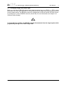
Enhanced Debug Mode Detection:
For MPC8xx and MPC555 targets, debug mode (Freeze) detection also works when the BDM connector pins VFLS0 and VFLS1 are not connected to the target. If not connected to VFLSx, this BDM
connector pins should be left open or tied to Vcc. The BDI uses the following algorithm to check if the
target is in debug mode (freezed):
BOOL PPC_TargetFreezed(void) {
if ((VFLS0 != 1) | (VFLS0 != 1)) return FALSE;
read debug port status;
if (status == freezed) return TRUE;
else
return FALSE;
© Copyright 1997-2001 by ABATRON AG Switzerland
V 1.16
bdiGDB for GNU Debugger, BDI2000 (MPC8xx/MPC5xx)
User Manual
7
2.1.1 Changing Target Processor Type
Before you can use the BDI2000 with an other target processor type (e.g. CPU32 <--> PPC), a new
setup has to be done (see Appendix A). During this process the target cable must be disconnected
from the target system. The BDI2000 needs to be supplied with 5 Volts via the BDI OPTION connector (Version A) or via the POWER connector (Version B). For more information see chapter 2.2.1
«External Power Supply».
!
To avoid data line conflicts, the BDI2000 must be disconnected from the target system while
programming the logic for an other target CPU.
© Copyright 1997-2001 by ABATRON AG Switzerland
V 1.16
bdiGDB for GNU Debugger, BDI2000 (MPC8xx/MPC5xx)
User Manual
8
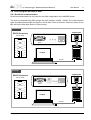
2.2 Connecting the BDI2000 to Power Supply
2.2.1 External Power Supply
The BDI2000 needs to be supplied with 5 Volts (max. 1A) via the BDI OPTION connector (Version A)
or via POWER connector (Version B). The available power supply from Abatron (option) or the enclosed power cable can be directly connected. In order to ensure reliable operation of the BDI2000,
keep the power supply cable as short as possible.
!
For error-free operation, the power supply to the BDI2000 must be between 4.75V and 5.25V DC.
The maximal tolerable supply voltage is 5.25 VDC. Any higher voltage or a wrong polarity
might destroy the electronics.
Version A
BDI OPTION
Connector
BDI
TRGT MODE
BDI MAIN
BDI OPTION
13
1
2
14
Vcc
GND
The green LED «BDI» marked light up when 5V power is connected to the BDI2000
Version
B
Rev.
B Version
GND 3
RS232
BDI
TRGT MODE
POWER
Connector
1 Vcc
2
4
POWER
LI
TARGET A
1 - NOT USED
2 - GROUND
3 - NOT USED
4 - GROUND
5 - NOT USED
6 - GROUND
7 - NOT USED
8 - GROUND
9 - NOT USED
10 - GROUND
11 - NOT USED
12 - Vcc (+5V)
13 - Vcc Target (+5V)
14 - Vcc (+5V)
TX RX
10 BASE-T
1 - Vcc (+5V)
2 - VccTGT
3 - GROUND
4 - NOT USED
TARGET B
The green LED «BDI» marked light up when 5V power is connected to the BDI2000
Please switch on the system in the following sequence:
• 1 --> external power supply
• 2 --> target system
© Copyright 1997-2001 by ABATRON AG Switzerland
V 1.16
bdiGDB for GNU Debugger, BDI2000 (MPC8xx/MPC5xx)
User Manual
9
2.2.2 Power Supply from Target System
The BDI2000 needs to be supplied with 5 Volts (max. 1A) via BDI MAIN target connector (Version A)
or via TARGET A connector (Version B). This mode can only be used when the target system runs
with 5V and the pin «Vcc Target» is able to deliver a current up to 1A@5V. For pin description and
layout see chapter 2.1 «Connecting the BDI2000 to Target». Insert the enclosed Jumper as shown
in figure below. Please ensure that the jumper is inserted correctly.
!
For error-free operation, the power supply to the BDI2000 must be between 4.75V and 5.25V DC.
The maximal tolerable supply voltage is 5.25 VDC. Any higher voltage or a wrong polarity
might destroy the electronics.
Version A
BDI OPTION
Connector
BDI
TRGT MODE
BDI MAIN
BDI OPTION
1
13
2
14
Jumper
The green LEDs «BDI» and «TRGT» marked light up when target is powered up
and the jumper is inserted correctly
Version B
3
RS232
BDI
TRGT MODE
POWER
Connector
1
2
4
POWER
1 - NOT USED
2 - GROUND
3 - NOT USED
4 - GROUND
5 - NOT USED
6 - GROUND
7 - NOT USED
8 - GROUND
9 - NOT USED
10 - GROUND
11 - NOT USED
12 - Vcc (+5V)
13 - Vcc Target (+5V)
14 - Vcc BDI2000 (+5V)
Jumper
LI
TARGET A
TX RX
10 BASE-T
1 - Vcc BDI2000 (+5V)
2 - Vcc Target (+5V)
3 - GROUND
4 - NOT USED
TARGET B
The green LEDs «BDI» and «TRGT» marked light up when target is powered up
and the jumper is inserted correctly
© Copyright 1997-2001 by ABATRON AG Switzerland
V 1.16
bdiGDB for GNU Debugger, BDI2000 (MPC8xx/MPC5xx)
User Manual
10
2.3 Status LED «MODE»
The built in LED indicates the following BDI states:
Version A
BDI
TRGT MODE
BDI MAIN
BDI OPTION
Version B
BDI
TRGT MODE
TARGET A
MODE LED
TARGET B
BDI STATES
OFF
The BDI is ready for use, the firmware is already loaded.
ON
The power supply for the BDI2000 is < 4.75VDC.
BLINK
The BDI «loader mode» is active (an invalid firmware is loaded or loading firmware is active).
© Copyright 1997-2001 by ABATRON AG Switzerland
V 1.16
bdiGDB for GNU Debugger, BDI2000 (MPC8xx/MPC5xx)
User Manual
11
2.4 Connecting the BDI2000 to Host
2.4.1 Serial line communication
Serial line communication is only used for the initial configuration of the bdiGDB system.
The host is connected to the BDI through the serial interface (COM1...COM4). The communication
cable (included) between BDI and Host is a serial cable. There is the same connector pinout for the
BDI and for the Host side (Refer to Figure below).
Version A
RS232 Connector
(for PC host)
RD
3
TD
7
RTS
8
CTS
6
DSR
1
DCD
4
2
GND
2
5
RD
5
GND
DTR
Target System
12345
MPC
8xx
6789
RS232
3
TD
7
RTS
CTS
8
DSR
6
4
DTR
1
DCD
LI
TX
RX
10 BASE-T
BDI2000
PC Host
Abatron AG
Swiss Made
RS232
Version B
RS232 Connector
(for PC host)
CTS
6
DSR
1
DCD
4
4
RTS
8
1
DTR
MPC
8xx
6789
RS232
POWER
LI
TX RX
10 BASE-T
TD
7
6
DCD
RD
3
8
DSR
GND
2
CTS
5
7
RTS
3
TD
2
RD
5
GND
Target System
12345
DTR
BDI2000
PC Host
Abatron AG
Swiss Made
RS232
© Copyright 1997-2001 by ABATRON AG Switzerland
V 1.16
bdiGDB for GNU Debugger, BDI2000 (MPC8xx/MPC5xx)
User Manual
12
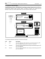
2.4.2 Ethernet communication
The BDI2000 has a built-in 10 BASE-T Ethernet interface (see figure below). Connect an UTP (Unshilded Twisted Pair) cable to the BD2000. For thin Ethernet coaxial networks you can connect a
commercially available media converter (BNC-->10 BASE-T) between your network and the
BDI2000. Contact your network administrator if you have questions about the network.
Version A
1
8
10 BASE-T
Connector
1 - TD+
2 - TD3 - RD+
4 - NC
5 - NC
6 - RD7 - NC
8 - NC
RS232
LI
TX
RX
10 BASE-T
Target System
Version B
1
RS232
POWER
LI
TX RX
8
MPC
5xx8xx
10 BASE-T
BDI2000
PC Host
Abatron AG
Swiss Made
Ethernet (10 BASE-T)
The following explains the meanings of the built-in LED lights:
LED
Name
Description
LI
Link
When this LED light is ON, data link is successful between the UTP
port of the BDI2000 and the hub to which it is connected.
TX
Transmit
When this LED light BLINKS, data is being transmitted through the UTP
port of the BDI2000
RX
Receive
When this LED light BLINKS, data is being received through the UTP
port of the BDI2000
© Copyright 1997-2001 by ABATRON AG Switzerland
V 1.16
bdiGDB for GNU Debugger, BDI2000 (MPC8xx/MPC5xx)
User Manual
13
2.5 Installation of the Configuration Software
On the enclosed diskette you will find the BDI configuration software and the firmware required for
the BDI2000. For Windows NT users there is also a TFTP server included.
For the initial configuration or to update the firmware, a PC running at least Windows 3.1 is required.
The following files are on the diskette.
b20ppcgd.exe
Configuration program (16bit Windows application)
b20ppcgd.hlp
Windows help file for the configuration program
b20ppcgd.xxx
Firmware for the BDI2000
ppcjed.xxx
JEDEC file for the BDI2000 logic device when working with a MPC8xx/5xx target
tftpsrv.exe
TFTP server for WindowsNT/ Windows95 (WIN32 console application)
*.cnf
Sample configuration files
*.def
Register definition files
bdisetup.zip
ZIP Archive with the Setup Tool sources for Linux / UNIX hosts.
Example of an installation process:
• Create a new directory on your hard disk, for example E:\bdi\ppc
• Copy the entire contents of the enclosed diskette into this directory
2.6 Initial configuration of the bdiGDB system
Before you can use the bdiGDB system, an initial setup has to be done (see Appendix A). During this
setup you define the following items and stores them in the flash memory of the BDI2000.
BDI2000 IP address
The BDI2000 is assigned an individual IP address. Ask your network administrator for a free one.
HOST IP address
The IP address of the host with the target configuration file has to be
known by the BDI2000.
Configuration file name
The name (including the path) of the file with the target configuration. The
string entered is used as the filename when accessing the configuration
file via TFTP. Use the naming convention of the host which holds the configuration file.
For more information about using the bdiGDB configuration program consult the online help.
Remark: Don't forget to press <Transmit> after you entered the configuration values.
Linux / UNIX:
The initial configuration of the BDI2000 can also be done with a command line utility (bdisetup) from
any Linux / UNIX host. In the ZIP Archive bdisetup.zip are all sources to build this utility. More information about this utility can be found in the bdisetup.c source file.
To build the setup utility use: gcc bdisetup.c bdidll.c -o bdisetup
© Copyright 1997-2001 by ABATRON AG Switzerland
V 1.16
bdiGDB for GNU Debugger, BDI2000 (MPC8xx/MPC5xx)
User Manual
14
2.7 Testing the BDI2000 to host connection
After the initial setup is done, you can test the communication between the host and the BDI2000.
There is no need for a target configuration file and no TFTP server is needed on the host.
• If necessary, disconnect the BDI2000 system from the Windows PC used for the initial
configuration.
• If not already done, connect the bdiGDB system to the network.
• Power-up the BDI2000.
• Start a Telnet client on the host and connect to the BDI2000 (the IP address you entered during initial configuration).
• If everything is okay, a sign on message like «BDI Debugger for Embedded PowerPC» and a
list of the available commands should be displayed in the Telnet window.
2.8 TFTP server for Windows NT
The bdiGDB system uses TFTP to access the configuration file and to load the application program.
Because there is no TFTP server bundled with Windows NT, Abatron provides a TFTP server application tftpsrv.exe. This WIN32 console application runs as normal user application (not as a system
service).
Command line syntax:
tftpsrv [p] [w]
Without any parameter, the server starts in read-only mode. This means, only read access request
from the client are granted. This is the normal working mode. The bdiGDB system needs only read
access to the configuration and program files.
The parameter [p] enables protocol output to the console window. Try it.
The parameter [w] enables write accesses to the host file system.
tftpsrv p
Starts the TFTP server and enables protocol output
tftpsrv p w
Starts the TFTP server, enables protocol output and write accesses are
allowed.
You may enter the TFTP server into the Startup group so the server is started every time you logon.
© Copyright 1997-2001 by ABATRON AG Switzerland
V 1.16
bdiGDB for GNU Debugger, BDI2000 (MPC8xx/MPC5xx)
User Manual
15
3 Using bdiGDB
3.1 Principle of operation
The firmware within the BDI handles the GDB request and accesses the target memory or registers
via the BDM interface. There is no need for any debug software on the target system. After loading
the code via TFTP debugging can begin at the very first assembler statement.
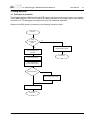
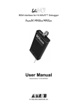
Whenever the BDI system is powered-up the following sequence starts:
Power On
initial
configuration
valid?
no
yes
activate BDI2000 loader
Get configuration file
via TFTP
Power OFF
Process target init list
Load program code
via TFTP and set the PC
RUN selected?
Start loaded program code
Process GDB request
Power OFF
© Copyright 1997-2001 by ABATRON AG Switzerland
V 1.16
bdiGDB for GNU Debugger, BDI2000 (MPC8xx/MPC5xx)
User Manual
16
Breakpoints:
There are two breakpoint modes supported. One of them (SOFT) is implemented by replacing application code with a TRAP instruction. The other (HARD) uses the built in breakpoint logic. If HARD is
used, only up to 4 breakpoints can be active at the same time.
The following example selects SOFT as the breakpoint mode:
BREAKMODE
SOFT
;<AGENT> SOFT or HARD, HARD uses PPC hardware breakpoints
All the time the application is suspended (i.e. caused by a breakpoint) the target processor remains
freezed.
© Copyright 1997-2001 by ABATRON AG Switzerland
V 1.16
bdiGDB for GNU Debugger, BDI2000 (MPC8xx/MPC5xx)
User Manual
17
3.2 Configuration File
The configuration file is automatically read by the BDI after every power on.
The syntax of this file is as follows:
; comment
[part name]
identifier parameter1
identifier parameter1
.....
[part name]
identifier parameter1
identifier parameter1
.....
etc.
parameter2 ..... parameterN
parameter2 ..... parameterN
; comment
parameter2 ..... parameterN
parameter2 ..... parameterN
Numeric parameters can be entered as decimal (e.g. 700) or as hexadecimal (0x80000).
3.2.1 Part [INIT]
The part [INIT] defines a list of commands which should be executed every time the target comes out
of reset. The commands are used to get the target ready for loading the program file. The SIM registers (chip select, clock, ...) are usually initialized with this command list.
WGPR register value
Write value to the selected general purpose register.
register
the register number 0 .. 31
value
the value to write into the register
Example: WGPR 0 5
WSPR register value
Write value to the selected special purpose register.
register
the register number
value
the value to write into the register
Example: WSPR 27 0x00001002 ; SRR1 : ME,RI
WREG name value
Write value to the selected CPU register by name
name
the register name (MSR,CR,XER,LR,CTR,DSISR,...)
value
the value to write into the register
Example: WREG MSR 0x00001002
WM8 address value
Write a byte (8bit) to the selected memory place.
address
the memory address
value
the value to write to the target memory
Example: WM8 0xFFFFFA21 0x04 ; SYPCR: watchdog disable ...
WM16 address value
Write a half word (16bit) to the selected memory place.
address
the memory address
value
the value to write to the target memory
Example: WM16 0x02200200 0x0002 ; TBSCR
WM32 address value
Write a word (32bit) to the selected memory place.
address
the memory address
value
the value to write to the target memory
Example: WM32 0x02200000 0x01632440 ; SIUMCR
© Copyright 1997-2001 by ABATRON AG Switzerland
V 1.16
bdiGDB for GNU Debugger, BDI2000 (MPC8xx/MPC5xx)
User Manual
18
SUPM cmdaddr dataaddr Starts a sequence of writes to the UPM RAM array.
cmdaddr
the address of the UPM command register
dataaddr
the address of the UPM data register
Example: SUPM 0x02200168 0x0220017c
WUPM command data
Write indirect to the UPM RAM array. The data is always written first.
command
this value is written to the UPM command register
data
this value is written to the UPM data register
Example: WUPM 0x00000001 0x0FFFEC04
DELAY value
Delay for the selected time. A delay may be necessary to let the clock PLL
lock again after a new clock rate is selected.
value
the delay time in milliseconds (1...30000)
Example: DELAY 500 ; delay for 0.5 seconds
© Copyright 1997-2001 by ABATRON AG Switzerland
V 1.16
bdiGDB for GNU Debugger, BDI2000 (MPC8xx/MPC5xx)
User Manual
19
3.2.2 Part [TARGET]
The part [TARGET] defines some target specific values.
CPUTYPE type
This value gives the BDI information about the connected CPU:
type
The CPU type from the following list:
MPC500 or MPC800
Example:
CPUTYPE MPC500
BDIMODE mode param
This parameter selects the BDI debugging mode. The following modes are
supported:
LOADONLY Loads and starts the application core. No debugging via
BDM.
AGENT
The debug agent runs within the BDI. There is no need
for any debug software on the target. This mode accepts
a second parameter. If RUN is entered as a second parameter, the loaded application will be started immediately, otherwise only the PC is set and BDI waits for GDB
requests.
Example:
BDIMODE AGENT RUN
CPUCLOCK value
The BDI needs to know how fast the target CPU runs after processing the
init list. The BDM communication speed is selected based on this value. If
this value defines a clock rate that is higher than the real clock, BDM communication may fail. When defining a clock rate slower than possible, BDM
communication still works but not as fast as possible.
Important: When programming the MPC555 internal flash, this value is
used to calculate the appropriate timing parameters.
value
the CPU clock in hertz
Example:
CPUCLOCK 25000000 ; CPU clock is 25.0MHz
BREAKMODE mode
This parameter defines how breakpoints are implemented. The current
mode can also be changed via the Telnet interface.
SOFT
This is the normal mode. Breakpoints are implemented
by replacing code with a TRAP instruction.
HARD
In this mode, the PPC breakpoint hardware is used.
Only 4 breakpoints at a time are supported.
Example:
BREAKMODE HARD ; enable use of break hardware
MMU XLAT
In order to support Linux kernel debugging when MMU is on, the BDI
translates effective (virtual) to physical addresses. This translation is done
based on the current MMU configuration. Currently only the Linux model
with 4k pages is supported. If this configuration line is present and address relocation active (MSR bits IR/DR), the BDI translates the addresses received from GDB before it accesses physical memory. For more
information see also chapter "Embedded Linux MMU Support". Addresses entered at the Telnet are never translated. Translation can be probed
with the Telnet command PHYS.
Example: MMU XLAT ;enable effective to physical address translation
© Copyright 1997-2001 by ABATRON AG Switzerland
V 1.16
bdiGDB for GNU Debugger, BDI2000 (MPC8xx/MPC5xx)
User Manual
20
WORKSPACE address
In order to access the floating-point registers of a MPC5xx microprocessor, the BDI needs a workspace of 8 bytes in target RAM. Enter the base
address of this RAM area.
address
the address of the RAM area
Example:
WORKSPACE 0x00000000
REGLIST list
With GDB version 5.0, the number of registers read from the target has
been increased. Additional registers like SR’s, BAT’s and SPR’s are requested when you select a specific PowerPC variant with the "set processor" command (see GDB source file rs6000-tdep.c). In order to be
compatible with older GDB versions and to optimize the time spent to read
registers, this parameter can be used. You can define which register group
is really read from the target. By default only STD are read and transferred.
This default is compatible with older GDB versions. The following names
are use to select a register group:
STD
The standard (old) register block. The FPR registers are
not read from the target but transferred. You can’t disable
this register group.
FPR
The floating point registers are read and transferred.
SR
not available for MPC8xx/5xx targets.
BAT
not available for MPC8xx/5xx targets
SPR
Some additional special purpose registers
AUX
The debug module special purpose registers
ALL
Include all register groups
Example:
REGLIST STD ; only standard registers
REGLIST STD FPR SPR ; all except SR and BAT
© Copyright 1997-2001 by ABATRON AG Switzerland
V 1.16
bdiGDB for GNU Debugger, BDI2000 (MPC8xx/MPC5xx)
User Manual
21
3.2.3 Part [HOST]
The part [HOST] defines some host specific values.
IP ipaddress
The IP address of the host.
ipaddress
the IP address in the form xxx.xxx.xxx.xxx
Example:
IP 151.120.25.100
FILE filename
The file name of the program file. This name is used to access the application file via TFTP.
filename
the filename including the full path
Example:
FILE F:\gnu\demo\mpc860\test.elf
FORMAT format [offset]
The format of the image file and an optional load address offset. Currently
binary, S-record, a.out and ELF formats are supported. If the image is already stored in ROM on the target, select ROM as the format. The optional
parameter "offset" is added to any load address read from the image file.
format
BIN, SREC, AOUT, ELF, IMAGE* or ROM
Example:
FORMAT ELF
FORMAT ELF 0x10000
LOAD mode
In Agent mode, this parameters defines if the code is loaded automatically
after every reset.
mode
AUTO, MANUAL
Example:
LOAD MANUAL
START address
The address where to start the program file. If this value is not defined and
the core is not in ROM, the address is taken from the code file. If this value
is not defined and the core is already in ROM, the PC will not be set before
starting the program file. This means, the program starts at the normal reset address (0x0100).
address
the address where to start the program file
Example:
START 0x1000
DEBUGPORT port
The TCP port GDB uses to access the target.
port
the TCP port number (default = 2001)
Example:
DEBUGPORT 2001
PROMPT string
This entry defines a new Telnet prompt. The current prompt can also be
changed via the Telnet interface.
Example:
PROMPT MPC860>
For a complete example see chapter «Introduction» or the file ads860.cnf on the distribution disk.
* Special IMAGE load format:
The IMAGE format is a special version of the ELF format used to load a Linux boot image into target
memory. When this format is selected, the BDI loads not only the loadable segment as defined in the
Program Header, it also loads the rest of the file up to the Section Header Table. The relationship
between load address and file offset will be maintained throughout this process. This way, the compressed Linux image and a optional RAM disk image will also be loaded.
© Copyright 1997-2001 by ABATRON AG Switzerland
V 1.16
bdiGDB for GNU Debugger, BDI2000 (MPC8xx/MPC5xx)
User Manual
22
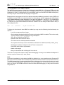
3.2.4 Part [FLASH]
The Telnet interface supports programming and erasing of flash memories. The bdiGDB system has
to know which type of flash is used, how the chip(s) are connected to the CPU and which sectors to
erase in case the ERASE command is entered without any parameter.
CHIPTYPE type
This parameter defines the type of flash used. It is used to select the correct programming algorithm.
format
AM29F, AM29BX8, AM29BX16, I28BX8, I28BX16,
AT49, AT49X8, AT49X16, MPC555, MPC565
Example:
CHIPTYPE AM29F
CHIPSIZE size
The size of one flash chip in bytes (e.g. AM29F010 = 0x20000). This value
is used to calculate the starting address of the current flash memory bank.
For MPC5xx internal flash, this parameter is not used.
size
the size of one flash chip in bytes
Example:
CHIPSIZE 0x80000
BUSWIDTH width
Enter the width of the memory bus that leads to the flash chips. Do not
enter the width of the flash chip itself. The parameter CHIPTYPE carries
the information about the number of data lines connected to one flash
chip. For example, enter 16 if you are using two AM29F010 to build a 16bit
flash memory bank.
For MPC5xx internal flash, this parameter is not used.
with
the width of the flash memory bus in bits (8 | 16 | 32)
Example:
BUSWIDTH 16
FILE filename
The name of the file to program into the flash. This name is used to access
the file via TFTP. This name may be overridden interactively at the Telnet
interface.
filename
the filename including the full path
Example:
FILE F:\gnu\demo\mpc860\bootrom.hex
FORMAT format [offset]
The format of the file and an optional address offset. The optional parameter "offset" is added to any load address read from the program file.
format
SREC, BIN, AOUT, ELF or IMAGE
Example:
FORMAT SREC
FORMAT ELF 0x10000
WORKSPACE address
If a workspace is defined, the BDI uses a faster programming algorithm
that runs out of RAM on the target system. Otherwise, the algorithm is processed within the BDI. The workspace is used for a 1kByte data buffer and
to store the algorithm code. There must be at least 2kBytes of RAM available for this purpose. Programming MPC5xx internal flash also needs a
workspace in target RAM.
address
the address of the RAM area
Example:
WORKSPACE 0x00000000
© Copyright 1997-2001 by ABATRON AG Switzerland
V 1.16
bdiGDB for GNU Debugger, BDI2000 (MPC8xx/MPC5xx)
ERASE address [mode]
User Manual
23
The flash memory may be individually erased via the Telnet interface. In
order to make erasing of multiple flash sectors easier, you can enter an
erase list. All entries in the erase list will be processed if you enter ERASE
at the Telnet prompt without any parameter. For MPC5xx internal flash,
this parameter has a different meaning. See below.
address
Address of the flash sector, block or chip to erase
mode
BLOCK, CHIP
Without this optional parameter, the BDI executes a sector erase. If supported by the chip, you can also specify
a block or chip erase.
Example:
ERASE 0x05040000 ;erase sector 4 of flash
ERASE 0x05060000 ;erase sector 6 of flash
ERASE 0x05000000 CHIP ;erase whole chip(s)
For the MPC555 internal flash, the BDI assumes the following structure of the address:
16 bit
module address
1 bit
C
7 bit
<reserved>
8 bit
block [0:7]
module address
The 16 most significant bits of the flash module address.
C
The censor bit. If this bit is set, the censor information is erased.
block
The bit mask to select the flash block to erase. Bit ordering is the same as
in the CMFCTL register (see MPC555 manual).
For the MPC565 internal flash, the BDI assumes the following structure of the address:
16 bit
module address
1 bit
7 bit
2 bit
C <reserved> sbb[0:1]
8 bit
block [0:7]
module address
The 16 most significant bits of the flash module address.
C
The censor bit. If this bit is set, the censor information is erased.
sbb*
The bit mask to select the small blocks to erase. Bit ordering is the same
as in the UC3FCTL register (see MPC565 manual).
block
The bit mask to select the flash block to erase. Bit ordering is the same as
in the UC3FCTL register (see MPC565 manual).
* The BDI does not write implicit any value to the UC3FMCRE registers. If small blocks are used, the
appropriate value has to be written to the UC3FMCRE registers via the BDI initialization list or via the
connected debugger.
© Copyright 1997-2001 by ABATRON AG Switzerland
V 1.16
bdiGDB for GNU Debugger, BDI2000 (MPC8xx/MPC5xx)
User Manual
24
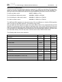
Supported Flash Memories:
There are currently 3 standard flash algorithm supported. The AMD, Intel and Atmel AT49 algorithm.
Almost all currently available flash memories can be programmed with one of this algorithm. The
flash type selects the appropriate algorithm and gives additional information about the used flash.
For 8bit only flash, select:
AM29F, I28BX8 or AT49
For 8/16 bit flash in 8bit mode, select:
AM29BX8, I28BX8 or AT49X8
For 8/16 bit flash in 16bit mode, select:
AM29BX16, I28BX16 or AT49X16
For 16bit only flash, select:
AM29BX16, I28BX16 or AT49X16
The AMD and AT49 algorithm are almost the same. The only difference is, that the AT49 algorithm
does not check for the AMD status bit 5 (Exceeded Timing Limits).
Only the AMD and AT49 algorithm support chip erase. Block erase is only supported with the AT49
algorithm. If the algorithm does not support the selected mode, sector erase is performed. If the chip
does not support the selected mode, erasing will fail. The erase command sequence is different only
in the 6th write cycle. Depending on the selected mode, the following data is written in this cycle (see
also flash data sheets): 0x10 for chip erase, 0x30 for sector erase, 0x50 for block erase.
The following table shows some examples:
Flash
x8
x 16
Chipsize
AM29F
-
0x020000
Am29F800B
AM29BX8
AM29BX16
0x100000
Am29DL323C
AM29BX8
AM29BX16
0x400000
Intel 28F032B3
I28BX8
-
0x400000
Intel 28F640J3A
I28BX8
I28BX16
0x800000
Intel 28F320C3
-
I28BX16
0x400000
AT49BV040
AT49
-
0x080000
AT49BV1614
AT49X8
AT49X16
0x200000
SST39VF160
-
AT49X16
0x200000
MPC555 internal flash (Mask: G, K, K2, K3, M)
MPC555
-
-
MPC565 internal flash
MPC565
Am29F010
© Copyright 1997-2001 by ABATRON AG Switzerland
V 1.16
bdiGDB for GNU Debugger, BDI2000 (MPC8xx/MPC5xx)
User Manual
25
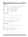
Examples:
ADS860 flash memory:
[FLASH]
CHIPTYPE
CHIPSIZE
BUSWIDTH
FILE
ERASE
ERASE
ERASE
ERASE
ERASE
ERASE
ERASE
ERASE
AM29F
;Flash type (AM29F | AM29BX8 | AM29BX16 | I28BX8 | I28BX16)
0x80000
;The size of one flash chip in bytes (e.g. AM29F010 = 0x20000)
32
;The width of the flash memory bus in bits (8 | 16 | 32)
E:\ada\demo\mpc860\bootrom.hex ;The file to program
0x02800000
;erase sector 0 of flash SIMM (MCM29F040)
0x02840000
;erase sector 1 of flash SIMM
0x02880000
;erase sector 2 of flash SIMM
0x028C0000
;erase sector 3 of flash SIMM
0x02900000
;erase sector 4 of flash SIMM
0x02940000
;erase sector 5 of flash SIMM
0x02980000
;erase sector 6 of flash SIMM
0x029C0000
;erase sector 7 of flash SIMM
MPC555 internal flash:
[INIT]
...
WSPR
638
...
[TARGET]
CPUTYPE
CPUCLOCK
...
[FLASH]
CHIPTYPE
WORKSPACE
FORMAT
FILE
ERASE
ERASE
0x00000802
MPC500
20000000
;IMMR: InternalRegs to 0x00400000, Flash enabled
;CPU type (MPC800 | MPC500)
;the CPU clock rate, used for flash timing calculation
MPC555
;Select MPC555 internal CDR MoneT Flash
0x007FC000 ;use internal SRAM array B for workspace
SREC
D:\abatron\bdi360\ppc\pro\mpc555.sss ;The file to program
0x004000FF ;Erase module A all sectors
0x004400FC ;Erase module B all sectors
MPC565 internal flash:
[INIT]
...
WSPR
638
...
[FLASH]
CHIPTYPE
WORKSPACE
FORMAT
FILE
ERASE
ERASE
0x00000802
;IMMR: InternalRegs to 0x00400000, Flash enabled
MPC565
;Select MPC565 internal CDR3 Flash
0x007F8000 ;use CALRAM A for workspace
SREC
D:\abatron\bdi360\ppc\pro\mpc565.sss ;The file to program
0x004000FF ;Erase module A all sectors
0x004800FF ;Erase module B all sectors
© Copyright 1997-2001 by ABATRON AG Switzerland
V 1.16
bdiGDB for GNU Debugger, BDI2000 (MPC8xx/MPC5xx)
User Manual
26
3.2.5 Part [REGS]
In order to make it easier to access target registers via the Telnet interface, the BDI can read in a
register definition file. In this file, the user defines a name for the register and how the BDI should
access it (e.g. as memory mapped, memory mapped with offset, ...). The name of the register definition file and information for different registers type has to be defined in the configuration file.
The register name, type, address/offset/number and size are defined in a separate register definition
file. This way, you can create one register definition file for the MPC860 that can be used for all possible positions of the internal memory map. You only have to change one entry in the configuration
file.
An entry in the register definition file has the following syntax:
name
type
addr
size
name
The name of the register (max. 12 characters)
type
The register type
GPR
SPR
MM
DMM1...DMM4
IMM1...IMM4
General purpose register
Special purpose register
Absolute direct memory mapped register
Relative direct memory mapped register
Indirect memory mapped register
addr
The address, offset or number of the register
size
The size (8, 16, 32) of the register
The following entries are supported in the [REGS] part of the configuration file:
FILE filename
The name of the register definition file. This name is used to access the
file via TFTP. The file is loaded once during BDI startup.
filename
the filename including the full path
Example:
FILE C:\bdi\regs\mpc8260.def
DMMn base
This defines the base address of direct memory mapped registers. This
base address is added to the individual offset of the register.
base
the base address
Example:
DMM1 0x01000
IMMn addr data
This defines the addresses of the memory mapped address and data registers of indirect memory mapped registers. The address of a IMMn register is first written to "addr" and then the register value is access using
"data" as address.
addr
the address of the Address register
data
the address of the Data register
Example:
DMM1 0x02200000
© Copyright 1997-2001 by ABATRON AG Switzerland
V 1.16
bdiGDB for GNU Debugger, BDI2000 (MPC8xx/MPC5xx)
User Manual
27
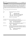
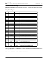
Example for a register definition (MPC860):
Entry in the configuration file:
[REGS]
DMM1
0x02200000
FILE
E:\bdi\mpc860\reg860.def
;Internal Memory Map Base Address
;The register definition file
The register definition file:
;name
type
addr
size
;------------------------------------------;
gpr0
GPR
0
sp
GPR
1
;
pc
SPR
26
; is SRR0
xer
SPR
1
lr
SPR
8
ctr
SPR
9
sprg0
SPR
272
sprg1
SPR
273
sprg2
SPR
274
sprg3
SPR
275
;
;
; DMM1 must be set to the internal memory map base address
;
siumcr
DMM1
0x0000
32
sypcr
DMM1
0x0004
32
;
mstat
DMM1
0x0178
16
padir
DMM1
0x0950
16
papar
DMM1
0x0952
16
paodr
DMM1
0x0954
16
padat
DMM1
0x0956
16
Now the defined registers can be accessed by name via the Telnet interface:
BDI> rd siumcr
BDI>rm padir 0xFF00
© Copyright 1997-2001 by ABATRON AG Switzerland
V 1.16
bdiGDB for GNU Debugger, BDI2000 (MPC8xx/MPC5xx)
User Manual
28
3.3 Debugging with GDB
Because the target agent runs within BDI, no debug support has to be linked to your application.
There is also no need for any BDI specific changes in the application sources. Your application must
be fully linked because no dynamic loading is supported.
3.3.1 Target setup
Target initialization may be done at two places. First with the BDI configuration file, second within the
application. The setup in the configuration file must at least enable access to the target memory
where the application will be loaded. Disable the watchdog and setting the CPU clock rate should
also be done with the BDI configuration file. Application specific initializations like setting the timer
rate are best located in the application startup sequence.
3.3.2 Connecting to the target
As soon as the target comes out of reset, BDI initializes it and loads your application code. If RUN is
selected, the application is immediately started, otherwise only the target PC is set. BDI now waits
for GDB request from the debugger running on the host.
After starting the debugger, it must be connected to the remote target. This can be done with the following command at the GDB prompt:
(gdb)target remote bdi2000:2001
bdi2000
This stands for an IP address. The HOST file must have an appropriate
entry. You may also use an IP address in the form xxx.xxx.xxx.xxx
2001
This is the TCP port used to communicate with the BDI
If not already suspended, this stops the execution of application code and the target CPU changes
to background debug mode.
Remember, every time the application is suspended, the target CPU is freezed. During this time no
hardware interrupts will be processed.
Note: For convenience, the GDB detach command triggers a target reset sequence in the BDI.
(gdb)...
(gdb)detach
... Wait until BDI has resetet the target and reloaded the image
(gdb)target remote bdi2000:2001
3.3.3 Breakpoint Handling
GDB inserts breakpoints by replacing code via simple memory read / write commands. There is no
command like "Set Breakpoint" defined in the GDB remote protocol. When breakpoint mode HARD
is selected, the BDI checks the memory write commands for such hidden "Set Breakpoint" actions.
If such a write is detected, the write is not performed and the BDI sets an appropriate hardware
breakpoint. The BDI assumes that this is a "Set Breakpoint" action when memory write length is 4
bytes and the pattern to write is 0x7D821008 (tw 12,r2,r2).
© Copyright 1997-2001 by ABATRON AG Switzerland
V 1.16
bdiGDB for GNU Debugger, BDI2000 (MPC8xx/MPC5xx)
User Manual
29
3.3.4 Embedded Linux MMU Support
The bdiGDB system supports Linux kernel debugging when MMU is on. Because GDB works with
effective (virtual) addresses, the BDI has to translate it before it can access physical memory. This
translation is done by reading back the current MMU setup (see also MPC8xx MMU description).
Currently only the Linux model with 4k pages is supported.
Because there is a sequence in the Linux startup code where address relocation is active (IR/DR set)
but MMU not setup (TLB’s are loaded manually, see head_8xx.s), the BDI supports also default translation. Default translation maps addresses in the range 0xC0000000 - 0xC07FFFFF to 0x00000000
- 0x007FFFFF. To help the BDI switching to default translation, it is necessary that the register
M_TWB is set to zero before address relocation is enabled. This can easily be done with an entry in
the configuration file.
WSPR
796
0x00000000
;M_TWB: invalidate TWB
To debug the Linux kernel when MMU is enabled you may use the following load and startup sequence:
• Load the compressed linux image
• Set a hardware breakpoint with the Telnet at a point where MMU is enabled. This can be easily
achieved with the following hardware range breakpoint
BDI> BI 0xC0000000 0xC00FFFFF
• Start the code with GO at the Telnet
• The Linux kernel is decompressed and started
• The system should stop as soon as address translation is enabled (normally at start_here)
• Disable the hardware breakpoint with the Telnet command CI.
• Start GDB with vmlinux as parameter
• Attach to the target
• Now you should be able to debug the Linux kernel
There are of course other ways to begin kernel debugging. You may set a hardware breakpoint directly at a point of interest (e.g. start_kernel)
Note:
Do not set a breakpoint in code where the MMU is disabled (e.g. at an exception entry). Because IR/
DR is not set there, the BDI will not translate any addresses and is not able to access virtual memory.
The MMU support that is implemented should help to bring up a Linux kernel but it makes no sense
to use it when debugging Linux applications. Also when KGDB runs, use it because it is saver. Only
when you cannot use KGDB because the kernel crashes, BDM debugging is a way to find out where
the problem is.
© Copyright 1997-2001 by ABATRON AG Switzerland
V 1.16
bdiGDB for GNU Debugger, BDI2000 (MPC8xx/MPC5xx)
User Manual
30
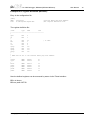
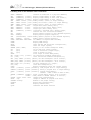
3.3.5 PPC Interrupt Handling
Almost all PPC interrupts causes an entry into debug mode. By default, the Debug Enable Register
(DER) is set as follows:
Debug Enable Register
Bit
Mnemonic
State
Describtion
0
-
1
RSTE
enabled
Reset Interrupt
2
CHSTPE
enabled
Check Stop
3
MCIE
enabled
Maschine Check Interrupt
4-5
-
6
EXTIE
7
ALIE
enabled
Alignment Interrupt
8
PRIE
enabled
Program Interrupt
9
FPUVIE
enabled
Floating-Point Unavailable Interrupt
10
DECIE
11-12
-
13
SYSIE
enabled
System Call Interrupt
14
TRE
enabled
Trace Interrupt
15-16
-
17
SEIE
enabled
Software Emulation Interrupt
18
ITLBMSE
Implementation Specific Instructuction TLB Miss
19
ITLBERE
Implementation Specific Instructuction TLB Error
20
DTLBMSE
Implementation Specific Data TLB Miss
21
DTLBERE
Implementation Specific Data TLB Error
22-27
-
28
LBRKE
enabled
Load/Store Breakpoint Interrupt
29
IBRKE
enabled
Instruction Breakpoint Interrupt
30
EBRKE
enabled
External Breakpoint Interrupt
31
DPIE
enabled
Developement Port Nonmaskable Request
External Interrupts
Decrementer Interrupt
If this is not appropriate for the application the default initialisation may be change with an entry in
the configuration file.
WSPR
149
0xFFE7400F
;DER: set debug enable register
© Copyright 1997-2001 by ABATRON AG Switzerland
V 1.16
bdiGDB for GNU Debugger, BDI2000 (MPC8xx/MPC5xx)
User Manual
31
3.4 Telnet Interface
A Telnet server is integrated within the BDI. The Telnet channel is used by the BDI to output error
messages and other information. Also some basic debug commands can be executed.
Telnet Debug features:
• Display and modify memory locations
• Display and modify general and special purpose registers
• Single step a code sequence
• Set hardware breakpoints (for code and data accesses)
• Load a code file from any host
• Start / Stop program execution
• Programming and Erasing Flash memory
During debugging with GDB, the Telnet is mainly used to reboot the target (generate a hardware reset
and reload the application code). It may be also useful during the first installation of the bdiGDB system or in case of special debug needs (e.g. setting breakpoints on variable access).
Because the Telnet server within the BDI generates no echo, enable local echo at your Telnet client.
Note:
The Telnet command RESET does only reset the target system. The configuration file is not loaded
again. If the configuration file has changed, use the Telnet command BOOT to reload it.
© Copyright 1997-2001 by ABATRON AG Switzerland
V 1.16
bdiGDB for GNU Debugger, BDI2000 (MPC8xx/MPC5xx)
User Manual
32
Following a list of the available Telnet commands:
"PHYS <address>
converts an effective to a physical address",
"MD
[<address>] [<count>] display target memory as word (32bit)",
"MDH
[<address>] [<count>] display target memory as half word (16bit)",
"MDB
[<address>] [<count>] display target memory as byte (8bit)",
"MM
<addr> <value> [<cnt>] modify word(s) (32bit) in target memory",
"MMH
<addr> <value> [<cnt>] modify half word(s) (16bit) in target memory",
"MMB
<addr> <value> [<cnt>] modify byte(s) (8bit) in target memory",
"MT
<address>
<count>
single word (32bit) memory test",
"MTH
<address>
<count>
single half word (16bit) memory test",
"MTB
<address>
<count>
single byte (8bit) memory test",
"MC
[<address>] [<count>] calculates a checksum over a memory range",
"MV
verifies the last calculated checksum",
"RD
[<name>]
display general purpose or user defined register",
"RDS
<number>
display special purpose register",
"RM
{<nbr>≠<name>} <value> modify general purpose or user defined register",
"RMS
<number>
<value>
modify special purpose register",
"UPMS <MCR-addr> <MDR-addr> set address of register MCR and MDR",
"UPMA
display UPMA setup",
"UPMB
display UPMB setup",
"BOOT
reset the BDI and reload the configuration",
"RESET
reset the target system",
"BREAK [SOFT | HARD]
display or set current breakpoint mode",
"GO
[<pc>]
set PC and start target system",
"TI
[<pc>]
trace on instuction (single step)",
"TC
[<pc>]
trace on change of flow",
"HALT
force target to enter debug mode",
"BI <from> [<to>] [<count>] set instruction hardware breakpoint",
"CI [<id>]
clear instruction hardware breakpoint(s)",
"BD [R|W] <addr> [<count>] [<data>] set data breakpoint (32bit access)",
"BDH [R|W] <addr> [<count>] [<data>] set data breakpoint (16bit access)",
"BDB [R|W] <addr> [<count>] [<data>] set data breakpoint ( 8bit access)",
"BDR <from> <to> [<count>]
set data breakpoint on a range",
"CD [<id>]
clear data breakpoint(s)",
"INFO
display information about the current state",
"LOAD
[<offset>] [<file> [<format>]] load program file to target memory",
"VERIFY [<offset>] [<file> [<format>]] verify a program file to target memory",
"PROG
[<offset>] [<file> [<format>]] program flash memory",
"
<format> : SREC or BIN or AOUT or ELF",
"ERASE [<address> [<mode>]] erase a flash memory sector, chip or block",
"
<mode> : CHIP, BLOCK or SECTOR (default is sector)",
"FLASH <type> <size> <bus>
change flash configuration",
"HOST
<ip>
change IP address of program file host",
"PROMPT <string>
defines a new prompt string",
"CONFIG
display BDI configuration",
"HELP
display command list",
"QUIT
terminate the Telnet session"
© Copyright 1997-2001 by ABATRON AG Switzerland
V 1.16
bdiGDB for GNU Debugger, BDI2000 (MPC8xx/MPC5xx)
User Manual
33
4 Specifications
Operating Voltage Limiting
5 VDC ± 0.25 V
Power Supply Current
typ. 500 mA
max. 1000 mA
RS232 Interface: Baud Rates
Data Bits
Parity Bits
Stop Bits
9’600,19’200, 38’400, 57’600,115’200
8
none
1
Network Interface
10 BASE-T
Serial Transfer Rate between BDI and Target
up to 16 Mbit/s
Supported target voltage
3.3 V and 5 V (TTL level)
Operating Temperature
+ 5 °C ... +60 °C
Storage Temperature
-20 °C ... +65 °C
Relative Humidity (noncondensing)
<90 %rF
Size
190 x 110 x 35 mm
Weight (without cables)
420 g
Host Cable length (RS232)
2.5 m
Specifications subject to change without notice
© Copyright 1997-2001 by ABATRON AG Switzerland
V 1.16
bdiGDB for GNU Debugger, BDI2000 (MPC8xx/MPC5xx)
User Manual
34
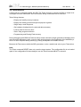
5 Environmental notice
Disposal of the equipment must be carried out at a designated disposal site.
6 Declaration of Conformity (CE)
© Copyright 1997-2001 by ABATRON AG Switzerland
V 1.16
bdiGDB for GNU Debugger, BDI2000 (MPC8xx/MPC5xx)
User Manual
35
7 Warranty
ABATRON Switzerland warrants the physical diskette, cable, BDI2000 and physical documentation
to be free of defects in materials and workmanship for a period of 24 months following the date of
purchase when used under normal conditions.
In the event of notification within the warranty period of defects in material or workmanship,
ABATRON will replace defective diskette, cable, BDI2000 or documentation. The remedy for breach
of this warranty shall be limited to replacement and shall not encompass any other damages, including but not limited loss of profit, special, incidental, consequential, or other similar claims.
ABATRON Switzerland specifically disclaims all other warranties- expressed or implied, including but
not limited to implied warranties of merchantability and fitness for particular purposes - with respect
to defects in the diskette, cable, BDI2000 and documentation, and the program license granted herein, including without limitation the operation of the program with respect to any particular application,
use, or purposes. In no event shall ABATRON be liable for any loss of profit or any other commercial
damage, including but not limited to special, incidental, consequential, or other damages.
Failure in handling which leads to defects are not covered under this warranty. The warranty is void
under any self-made repair operation except exchanging the fuse.
© Copyright 1997-2001 by ABATRON AG Switzerland
V 1.16
bdiGDB for GNU Debugger, BDI2000 (MPC8xx/MPC5xx)
User Manual
36
Appendices
A BDI2000 Setup/Update
First make sure that the BDI is properly connected (see Chapter 2.1 to 2.4).
!
To avoid data line conflicts, the BDI2000 must be disconnected from the target system while
programming the logic for an other target CPU (see Chapter 2.1.1).
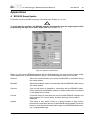
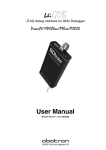
dialog box «BDI2000 Update/Setup»
Before you can use the BDI2000 together with the GNU debugger, you must store the initial configuration parameters in the BDI2000 flash memory. The following options allow you to do this:
Channel
Select the communication port where the BDI2000 is connected during
this setup session.
Baudrate
Select the baudrate used to communicate with the BDI2000 loader during
this setup session.
Connect
Click on this button to establish a connection with the BDI2000 loader.
Once connected, the BDI2000 remains in loader mode until it is restarted
or this dialog box is closed.
Current
Press this button to read back the current loaded BDI2000 software and
logic versions. The current loader, firmware and logic version will be
displayed.
Update
This button is only active if there is a newer firmware or logic version
present in the execution directory of the bdiGDB setup software. Press this
button to write the new firmware and/or logic into the BDI2000 flash memory / programmable logic.
© Copyright 1997-2001 by ABATRON AG Switzerland
V 1.16
bdiGDB for GNU Debugger, BDI2000 (MPC8xx/MPC5xx)
User Manual
37
BDI IP Address
Enter the IP address for the BDI2000. Use the following format:
xxx.xxx.xxx.xxx e.g.151.120.25.101
Ask your network administrator for assigning an IP address to this
BDI2000. Every BDI2000 in your network needs a different IP address.
Subnet Mask
Enter the subnet mask of the network where the BDI is connected to.
Use the following format: xxx.xxx.xxx.xxxe.g.255.255.255.0
A subnet mask of 255.255.255.255 disables the gateway feature.
Ask your network administrator for the correct subnet mask.
Default Gateway
Enter the IP address of the default gateway. Ask your network administrator for the correct gateway IP address. If the gateway feature is disabled,
you may enter 255.255.255.255 or any other value..
Config - Host IP Address Enter the IP address of the host with the configuration file. The configuration file is automatically read by the BDI2000 after every start-up.
Configuration file
Enter the full path and name of the configuration file.
e.g. D:\gnu\config\bdi\ads860bdi.cnf
For information about the syntax of the configuration file see the bdiGDB
User manual. This name is transmitted to the TFTP server when reading
the configuration file.
Transmit
Click on this button to store the configuration in the BDI2000 flash
memory.
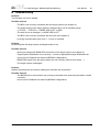
In rare instances you may not be able to load the firmware in spite of a correctly connected BDI (error
of the previous firmware in the flash memory). Before carrying out the following procedure, check
the possibilities in Appendix «Troubleshooting». In case you do not have any success with the
tips there, do the following:
• Switch OFF the power supply for the BDI and open the unit as
described in Appendix «Maintenance»
• Place the jumper in the «INIT MODE» position
• Connect the power cable or target cable if the BDI is powered
from target system
• Switch ON the power supply for the BDI again and wait until the
LED «MODE» blinks fast
INIT MODE
• Turn the power supply OFF again
DEFAULT
• Return the jumper to the «DEFAULT» position
• Reassemble the unit as described in Appendix «Maintenance»
© Copyright 1997-2001 by ABATRON AG Switzerland
V 1.16
bdiGDB for GNU Debugger, BDI2000 (MPC8xx/MPC5xx)
User Manual
38
B Troubleshooting
Problem
The firmware can not be loaded.
Possible reasons
• The BDI is not correctly connected with the target system (see chapter 2).
• The power supply of the target system is switched off or not in operating range
(4.75 VDC ... 5.25 VDC) --> MODE LED is OFF or RED
• The built in fuse is damaged --> MODE LED is OFF
• The BDI is not correctly connected with the Host (see chapter 2).
• A wrong communication port (Com 1...Com 4) is selected.
Problem
No working with the target system (loading firmware is ok).
Possible reasons
• Wrong pin assignment (BDM/JTAG connector) of the target system (see chapter 2).
• Target system initialization is not correctly --> enter an appropriate target initialization list.
• An incorrect IP address was entered (BDI2000 configuration)
• BDM/JTAG signals from the target system are not correctly (short-circuit, break, ...).
• The target system is damaged.
Problem
Network processes do not function (loading the firmware was successful)
Possible reasons
• The BDI2000 is not connected or not correctly connected to the network (LAN cable or media
converter)
• An incorrect IP address was entered (BDI2000 configuration)
© Copyright 1997-2001 by ABATRON AG Switzerland
V 1.16
bdiGDB for GNU Debugger, BDI2000 (MPC8xx/MPC5xx)
User Manual
39
C Maintenance
The BDI needs no special maintenance. Clean the housing with a mild detergent only. Solvents such
as gasoline may damage it.
If the BDI is connected correctly and it is still not responding, then the built in fuse might be damaged
(in cases where the device was used with wrong supply voltage or wrong polarity). To exchange the
fuse or to perform special initialization, please proceed according to the following steps:
!
Observe precautions for handling (Electrostatic sensitive device)
Unplug the cables before opening the cover.
Use exact fuse replacement (Microfuse MSF 1.6 AF).
Swiss Made
1.1 Unplug the cables
2
2.1 Remove the two plastic caps that cover the screws on target front side
(e.g. with a small knife)
2.2 Remove the two screws that hold the front panel
BDI
3
Abatron AG
BDI2000
1
TRGT MODE
BDI MAIN
BDI OPTION
3.1 While holding the casing, remove the front panel and the red elastig sealing
casing
elastic sealing
front panel
© Copyright 1997-2001 by ABATRON AG Switzerland
V 1.16
bdiGDB for GNU Debugger, BDI2000 (MPC8xx/MPC5xx)
4
User Manual
40
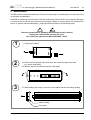
4.1 While holding the casing, slide carefully the print in position as shown in
figure below
Jumper settings
DEFAULT
INIT MODE
Fuse Position
Version B
Fuse Position
Version A
Pull-out carefully the fuse and replace it
Type: Microfuse MSF 1.6AF
Manufacturer: Schurter
5
Reinstallation
5.1 Slide back carefully the print. Check that the LEDs align with the holes in the
back panel.
5.2 Push carefully the front panel and the red elastig sealing on the casing.
Check that the LEDs align with the holes in the front panel and that the
position of the sealing is as shown in the figure below.
casing
elastic sealing
back panel
front panel
5.3 Mount the screws (do not overtighten it)
5.4 Mount the two plastic caps that cover the screws
5.5 Plug the cables
!
Observe precautions for handling (Electrostatic sensitive device)
Unplug the cables before opening the cover.
Use exact fuse replacement (Microfuse MSF 1.6 AF).
© Copyright 1997-2001 by ABATRON AG Switzerland
V 1.16
bdiGDB for GNU Debugger, BDI2000 (MPC8xx/MPC5xx)
User Manual
41
D Trademarks
All trademarks are property of their respective holders.
© Copyright 1997-2001 by ABATRON AG Switzerland
V 1.16