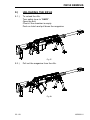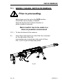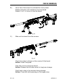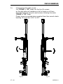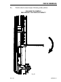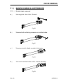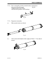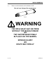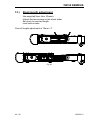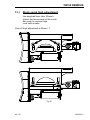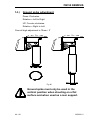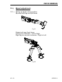
1
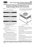
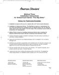
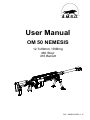
A.M.S.D.
User Manual
OM 50 NEMESIS
12.7x99mm / 50Bmg
460 Steyr
416 Barrett
FM – OM50/2010/R1.0 - E
FM – OM50/2010/R1.0 – E
User Manual
OM 50 NEMESIS
Models : Mk4, Mk5, Mk5-NV
1 - 68
19/02/2011
OM 50 NEMESIS
TABLE OF CONTENTS
Chapter
Subject (s)
Page Number
Safety rules
Clearing the weapon
Blast effect safety rules
4
4
5
A
Introduction
6
B
Technical information
8
C
C.1.
C.2.
C.3.
Models & variants
Mk4
Mk5
Mk5-Nv
9
9
9
D
D.1.
D.2.
D.3.
D.4.
D.5.
D.6.
D.7.
Standard equipment
5rds box mag. & manual feeding block
Field cleaning kit
Bolt tool
MilDial
carrying case, Negrini 1640
wrench set, PB 211H6
Scope ring set, (Ø30, 34, 35)
10
10
11
11
11
11
11
E
E.1
E.2
E.3
E.4
E.5
E.6
E.7
E.8
E.9
E.10
E.11
E.12
E.13
E.14
E.15.
E.16.
Accessories, basic spare parts & tools
Armory, bolt tool
Armory, bolt head repair kit
Armory, cleaning kit
Armory, gauges kits
Broken case / shell extractor
X-tra large bipod skids kit
Field, firing pin kit
Saddle / top rail kit with low saddle rail
Saddle rail, raised
Top rail, long
Top rail, short
Side rail short, low or raised
Side rail long, low or raised
Slings
Stuck case / shell extractor
Sound suppressor
12
12
12
13
14
14
14
14
15
15
15
15
15
16
16
16
1
1.1.
1.2.
Weapon setup
Bolt storing setup
Bolt check
17
17
2.
Arming the firing pin
18
3.
Bolt lubrication
20
2 - 68
19/02/2011
OM 50 NEMESIS
Chapter
Subject (s)
4.
Firing pin and shroud removal
22
5.
Bolt insertion
25
6.
Stock setup
28
7.
Loading the magazine
30
8.
Loading the rifle
31
9.
Unloading the rifle
33
10.
Barrel change, switch or removal
34
11.
11.1.
11.3.
Muzzle brake & suppressor
Muzzle brake removal
Suppressor assembly
39
40
12.
Stock length adjustment
42
13.
Stock comb high adjustment
43
14.
Ground spike adjustment
44
15.
Bipod adjustment
45
16.
16.1.
16.2.
16.3.
16.4.
Preventive maintenance procedures
General maintenance
Specific maintenance
Rifle cleaning schedules
Component service / replacement intervals
48
48
50
50
17.
Troubleshooting
51
18.
Broken shell extractor
52
19.
Stuck case extractor
56
20.
Mildial
58
21.
21.1.
Zeroing the rifle
Zeroing target
66
67
22.
Limited warranty
68
23.
Limitation of warranty
68
3 - 68
Page Number
19/02/2011
OM 50 NEMESIS
SAFETY RULES
Rule N°1
Treat every weapon as if it is loaded.
Rule N°2
Never point a weapon at anything or anybody that
you do not intend to harm or destroy or in a direction
where an unintentional discharge may result in damage
to property, injury or death.
Rule N°3
Never place your finger into the trigger guard until
you are ready to fire the weapon.
Rule N°4
Be sure of your target and of what’s behind it before firing
Rule N°5
Always wear eye & ear protection when firing a weapon.
Rule N°6
Clear every weapon before handling it.
CLEARING THE WEAPON
A.)
B.)
C.)
D.)
E.)
Rotate the safety lever to “SAFE”
Open the bolt
Remove the magazine
Inspect the chamber for the presence of
a live round or empty case
Visually:
look at the chamber through opened ejection port
Physically:
Insert index finger through ejection port to feel the
presence of a round or empty case in the chamber.
Empty live rounds from the magazine.
Remove and store any live rounds and/or empty cases
from whiting the weapon or magazine before handling
the weapon further.
4 - 68
19/02/2011
OM 50 NEMESIS
BLAST EFFECT SAFETY RULES
To reduce the recoil felt by the shooter this rifle is equipped with a high
efficiency muzzle brake.
In order to reduce the recoil, a major part of the gases released
when firing a round create a reverse thrust in the muzzle brake. This
generates “THRUST ZONES”, also called “BLAST.” Avoid these zones
while weapon is in use.
Debris from the ground could be projected at high speed and
could cause injuries to bystanders. Therefore, it is important to clear the
surface of small objects prior to shooting.
There should be a minimum of 2m between teams shooting in line.
Shooting in closer position will place shooters in the Blast zone.
When shooting as a team, the spotter must have his shoulders at the
level of the shooter’s hips and be as close as possible to him to be in
the SAFE ZONE.
SHORT BARREL: TRUST PATTERN
LONG BARREL: THRUST PATTERN
5 - 68
19/02/2011
OM 50 NEMESIS
A.)
INTRODUCTION
A.1.)
GENERAL INFORMATION
PREPARATION FOR STORAGE OR SHIPMENT.
Except in extreme situations, the rifle should always be stored and
transported only in an airtight, watertight carrying case.
RIFLE REPAIRS
Rifles should only be repaired by A.M.S.D. SA or
by a qualified professional that has been approved by A.M.S.D. SA.
If you must ship your weapon to be repaired remember to send the
whole weapon assembly (not just the damaged part) and to use an
airtight, waterproof carrying case as described above.
A.2.)
IDENTIFICATION OF MAJOR COMPONENTS
(1)
(2)
(3)
(4)
(5)
(6)
(7)
(8)
(9)
(10)
(11)
(12)
(13)
(14)
(15)
(16)
(17)
(18)
(19)
(20)
(21)
BARREL
BIPOD
BIPOD SKID PLATE
BOLT
BOLT STOP
COMB
FLUSH CUPS
FOREND
GROUND SPIKE
MAG. CATCH LEVER
MAGAZINE / MANUAL FEEDING BLOCK
MUZZLE BRAKE
PISTOL GRIP
RECOIL PAD
SADDLE RAIL
SAFETY LEVER
SIDE RAIL
STOCK JOINT
TOP RAIL
TRIGGER SHOE
UPPER RECEIVER
6 - 68
19/02/2011
OM 50 NEMESIS
7 - 68
19/02/2011
OM 50 NEMESIS
B.)
SPECIFICATIONS
Calibers
12.7x99mm
Overall length, stock collapsed
Overall length, stock fully extended
Overall length, stock folded
50 Bmg
460 Steyr
416 Barrett
1338mm
1413mm
1092mm
52.7”
55.6”
43”
900mm
800mm
700mm
600mm
450mm
35.5”
31.5”
27.5”
23.5”
17.75
381mm
356mm
279mm
15”
14”
11”
Barrels length (w/o muzzle brake)
Twist
50Bmg
460 Steyr
416 Barrett
Twist direction
Nbr of lands & grooves
Weight with 700mm / 27.5” barrel
Mk4
Mk5
Mk5-Nv
Right
6
11.4Kg
13.4Kg
13.8Kg
25Lbs
29.5Lbs
30.4Lbs
B.1.) CAPABILITIES
Ammunition type:
Muzzle velocity:
Energy:
Effective range:
Maximum range:
8 - 68
Standard M33 ammunition
with 700mm / 27.5” barrel
850m/s – 2800 f/s
15250 joules
approximately 1850m / 2000 yards
approximately 6500m / 7000 yards
19/02/2011
OM 50 NEMESIS
C.)
MODELS & VARIANTS
C.1.)
MK4
Fixed fully adj. stock, 700mm Barrel.
1x
Field cleaning kit
1x
Bolt tool
1x
Manual feeding block
1x
Negrini, 1640 carry case
1x
PB 211H6, wrench set
C.2.)
MK5
Folding fully adj. stock, 700mm Barrel, Bipod & ground spike.
1x
5rds Box mag.
1x
Field cleaning kit
1x
Bolt tool
1x
Manual feeding block
1x
MilDial
1x
Negrini, 1640
1x
PB 211H6, wrench set
C.3.)
MK5-NV
Folding fully adj. stock, 700mm Barrel, Bipod & ground spike, integral tapered rail.
2x,
5rds Box mag.
1x,
Field cleaning kit
1x,
Bolt tool
1x,
Manual feeding block
1x,
MilDial
1x,
Negrini, 1640
1x,
PB 211H6, wrench set
1x,
Scope ring set (choice : Ø30, 34, 35)
9 - 68
19/02/2011
OM 50 NEMESIS
D.)
STANDARD EQUIPMENT’S
Equipment may vary depending on purchased model
D.1.)
5rds box mag. & manual feeding block
D.2.)
Field cleaning kit
10 - 68
19/02/2011
OM 50 NEMESIS
D.3.)
Bolt tool
D.4.)
MilDial
75cm
70cm
60
cm
7
85m
25°
90m
30°
95m
20°
10°
100m
6
cm
55
50cm
TA
RG
ET
RA
NG
E
DE
LA
CIB
LE
DIS
TA
NC
E
5
57 5m
.5
6 m
62 0m
.5
65 m
67.5 m
70 m
50
72.5 m
°
m
75m
77.5m
80m
40°
°
60
35°
m
50 m
.5
52
55
°
45°
65
cm
1m
95cm
90cm
85cm
8
10
CIBLE
TARGET
9
METRIC UNITS
80cm
© 2007, COPYRIGHT A.M.S.D., GENEVA SWITZERLAND
MILDOT DIAL
5
45cm
4.8
4.6
4.4
4.2
40cm
4
3.8
3.6
35cm
3.4
3.2
5 MILS
1 MIL
3
0.2 MIL
0.8 MIL
1. ALIGNER LA TAILLE DE LA CIBLE AVEC
LA VALEUR MESUREE EN MILS ( MILDOT )
2. LIRE LA DISTANCE DE LA CIBLE
DANS LA FENETRE DE GAUCHE
2.6
2.4
1.7
1.6
20
cm
1.4
15cm
1
1.1
10cm
D.5.)
1.2
MILS
1.3
1. ALIGN TARGET SIZE WITH
MEASURED MILS ( MILDOT ) VALUE
2. READ TARGET DISTANCE IN LEFT WINDOW
TAILLE DE LA CIBLE
TARGET SIZE
25cm
2.2
1.9 2
1.8
USER INSTRUCTIONS
PATENT PENDING
P/N : MDEF-M
MADE IN SWITZERLAND
30cm
2.8
INSTRUCTIONS D' UTILISATION
Carrying case, Negrini1640
Not Illustrated
D.6.)
Wrench set, PB 211H6
D.7.)
Scope ring set (Ø30, 34, 35)
Not Illustrated
11 - 68
19/02/2011
OM 50 NEMESIS
E.)
ACCESSORIES, BASIC SPARE PARTS & TOOLS
E.1.)
Armory, bolt tool
E.2.)
Armory, bolt head repair kit
E.3.)
Armory, cleaning kit
12 - 68
19/02/2011
OM 50 NEMESIS
E.4.)
Armory, gauges kits
Bolt, head gauges
Barrel, chamber gauges
Barrel, Dial. 12.63mm to 12.72mm gauges
Barrel, 12.9mm to 12.99mm rifling gauge
13 - 68
19/02/2011
OM 50 NEMESIS
E.5.)
Broken case / shell extractor
E.6.)
X-tra large bipod skids kit
E.7.)
Field, firing pin kit
E.8.)
Saddle / top rail kit with low saddle rail.
14 - 68
19/02/2011
OM 50 NEMESIS
E.9.)
Saddle rail, raised.
E.10.) Top rail, long.
E.11.) Top rail, short.
Top rails could be ordered either with 30Moa or 45Moa depression.
2 dots at rear = 30Moa
3 dots at rear = 45Moa
E.12.) Side rail short, low or raised.
E.13.) Side rail long, low or raised.
15 - 68
19/02/2011
OM 50 NEMESIS
E.14.) Slings, NOT ILLUSTRATED
a.)
b.)
c.)
Biathlon type
Standard single strap type
Standard double strap type
E.15.) Stuck case / shell extractor
E.16.) Sound suppressor
Dimensions
Calibers
Overall diameter
Overall length
Weapon length addition
Weight
Threads
16 - 68
12.7x99mm
50 Bmg
460 Steyr
416 Barrett
80mm
3.15”
513mm
20.2”
163mm
6.4”
2.74Kg
6Lbs
M30x1.5 Left hand twist
19/02/2011
OM 50 NEMESIS
1.)
WEAPON SETUP
1.1.)
Bolt storing setup
Fig 1.
1.2.)
Bolt Check
Prior to inserting the bolt in the rifle
1.2.1.) Check Extractor function
1.2.2.) Visually inspect firing pin for erosion or wear marks
1.2.3.) Check Ejector plunger function
Fig 2.
17 - 68
19/02/2011
OM 50 NEMESIS
2.)
ARMING THE FIRING PIN
Prior to inserting the bolt in the rifle
firing pin must be armed
2.1.)
Use either bolt tool or 3mm Hex wrench to proceed
Fig 3.
IMPORTANT NOTICE
BOLT MUST BE STORED WITH
FIRING PIN SPRING IN RELEASED STATE
Weapon may fail to fire may result if not stored as per Fig. 1.
If the bolt is not stored properly, firing pin spring will need to be replaced
more frequently to ensure proper function.
18 - 68
19/02/2011
OM 50 NEMESIS
2.2.)
Rotate the firing pin shroud 60° clockwise.
Fig 4.
2.3.)
Bolt is now set
Fig 5.
19 - 68
19/02/2011
OM 50 NEMESIS
3.)
BOLT LUBRICATION
Prior to inserting the bolt in the rifle.
3.1.)
Lubricate firing pin cam path
Fig 6.
3.2.)
Lubricate bolt lugs
Fig 7.
20 - 68
19/02/2011
OM 50 NEMESIS
3.3.)
Lubricate guiding slot
Fig 8.
IMPORTANT NOTICE
Grease must be used for bolt lubrication
Bolt lubrication process must be repeated every 25 to 50 rounds,
depending on weather and/or environmental conditions.
21 - 68
19/02/2011
OM 50 NEMESIS
4.)
FIRING PIN AND SHROUD REMOVAL
4.1.)
Insert the 3mm Hex wrench through the shroud.
Fig 9.
4.2.)
Rotate the assembly 90° counter clockwise.
Fig 10.
4.3.)
Extract the assembly from the bold body.
Fig 11.
22 - 68
19/02/2011
OM 50 NEMESIS
4.4.)
Lubricate the contact surfaces with grease.
Fig 12.
4.5.)
Insert the firing pin assembly back in the bolt body.
Fig 13.
23 - 68
19/02/2011
OM 50 NEMESIS
4.6.)
Push the assembly forward and rotate 90° clockwise.
Fig 14.
4.7.)
Once the shroud is in the proper position,
you should be able to extract the wrench without force.
Fig 15.
24 - 68
19/02/2011
OM 50 NEMESIS
5.)
BOLT INSERTION
PRIOR TO INSERTION
Safety lever MUST be set to either FIRE or SAFE, as per
shown in fig. 16, prior to introducing the bolt into the receiver.
Trying to insert the bolt by force with safety lever
set to SAFE – BOLT LOCKED will permanently damage
the trigger system and will void the warranty.
Fig 16.
25 - 68
19/02/2011
OM 50 NEMESIS
5.1.)
To insert the bolt in the weapon:
If the weapon is on a flat surface, a stand or a table:
Pull down bipod legs for steady handling.
If you are in the field:
Hold weapon vertical while keeping muzzle brake
on your shoe to prevent barrel obstruction.
To open the bipod:
Squeeze both legs together and turn clockwise.
Fig 17.
26 - 68
19/02/2011
OM 50 NEMESIS
5.2.)
Push the bolt in to the receiver, a slight up or down rotation of
the bolt handle will help bolt stop to engage the guiding slot.
Fig 18.
5.3.)
Lock the bolt and dry fire to check proper function of trigger,
fully open the bolt until the bolt stop engages and close
the bolt again, either dry fire or set the rifle on safety.
Fig 19.
Your rifle is now ready for operation.
27 - 68
19/02/2011
OM 50 NEMESIS
6.)
STOCK SETUP
6.1.)
To open the stock:
Pull or push up the stock
holding it as close as possible from stock joint
and rotate counter clockwise, until it locks in position.
Fig 20.
6.2.)
To open the ground spike:
Pull forward and rotate clockwise,
until it’s locked in position.
Fig 21.
Ground spike must only be used in the
vertical position when shooting on a flat
surface and when used as a rear support.
28 - 68
19/02/2011
OM 50 NEMESIS
6.3.)
Using the ground spike for target follow-up
The ground spike can be used at a 45° angle to shoot from
shoulder to follow up moving target or from high grounds down.
Fig 22.
29 - 68
19/02/2011
OM 50 NEMESIS
7.)
LOADING THE MAG
7.1.)
To load the magazine:
Push on both sides while introducing cartridges from
the front to the back, repeat until desired amount of
rounds is reached.
Maximal magazine capacity: 5 rounds
Fig 23.
DO NOT LEAVE ROUNDS IN THE MAGAZINE
FOR AN EXTENDED PERIOD OF TIME AS THIS
MAY CAUSE THE SPRING TO LOSE
TENSION LEADING TO MALFUNCTION.
30 - 68
19/02/2011
OM 50 NEMESIS
8.)
LOADING THE RIFLE
8.1.)
To Load the rifle:
Insert loaded magazine, front end first as shown
Rotate clockwise until it locks
Check if magazine is properly locked
During magazine insertion
Bolt can either be closed or opened.
Fig 24.
8.2.)
Loaded weapon handling.
Fig 25.
31 - 68
19/02/2011
OM 50 NEMESIS
8.3.)
Removing the safety:
From either “SAFE” or “SAFE BOLT LOCKED”
Turn safety lever to “FIRE” as shown in Fig. 26
Remove safety only when in proper shooting position.
Fig 26.
OM 50 NEMESIS Weapon system
has a built–in passive safety measure.
All the trigger parts are dynamically balanced to sustain a 6-axis drop
with a live round in the chamber & safety lever on FIRE position.
Nevertheless, an operator should not rely soley on the mechanical
safety devices
Use extreme caution while handling the weapon loaded or not.
32 - 68
19/02/2011
OM 50 NEMESIS
9.)
UNLOADING THE RIFLE
9.1.)
To unload the rifle:
Turn safety lever to “SAFE”.
Open the bolt.
Check if the chamber is empty.
Push on Latch and pull down the magazine.
Fig 27.
9.2.)
Pull out the magazine from the rifle.
Fig 28.
33 - 68
19/02/2011
OM 50 NEMESIS
10.)
BARREL CHANGE, SWITCH OR REMOVAL
Prior to proceeding.
Safety lever must be set on the SAFE position
Check that rifle is properly unloaded
Open the bolt & check if barrel chamber is
empty visually & manually
Barrel switch has to be made in a
clean as possible environment
10.1.) To take the barrel of the receiver
A.)
Use a 6mm Hex wrench to unlock the five (5) screws
on the right side of the rifle,
once screws are running free rotate each of them
one (1) turn to give enough play space.
Fig 29.
34 - 68
19/02/2011
OM 50 NEMESIS
B.)
Use a 3mm Hex wrench to activate the inner pusher
Rotate clockwise until resistance is encountered
Rotate ½ to ¾ of a turn to free the barrel.
Fig 30.
C.)
Slide out the barrel from the receiver
Fig 31.
Check all contact surfaces on the receiver & the barrel
Action: Clean if required.
If the rifle is to be stored w/o barrel:
Action: Release the left side screw for long term storage.
If bolt has to stay in the receiver during storage:
Action: Close bolt while pressing on the trigger shoe
35 - 68
19/02/2011
OM 50 NEMESIS
10.2.)
Reassembly of the barrel:
Hold the rifle in a vertical position.
Insert barrel with locking ring notch toward top picatinny rail.
Close the bolt to ensure proper positioning of the barrel.
IMPORTANT NOTICE
Bolt has to be opened prior to barrel insertion
Fig 32.
36 - 68
Fig 33.
19/02/2011
OM 50 NEMESIS
A.)
Unscrew the left pusher screw.
In a “DOWN” to “UP” order turn the five (5) screws
on the right side until resistance is felt on each on of them,
then start applying torque to each screw, following the same
“DOWN” to “UP“ order.
Proper torque is reached when supplied 6mm Hex wrench starts
bending 15 to 20 mm / 9/16” to 3/4”.
Fig 34.
37 - 68
Fig 35.
19/02/2011
OM 50 NEMESIS
B.)
Double check screw torque following order pattern.
FAILURE TO COMPLY
MAY RESULT IN POOR ACCURACY
Fig 35.
38 - 68
19/02/2011
OM 50 NEMESIS
11.)
MUZZLE BRAKE & SUPPRESSOR
11.1.)
Muzzle brake removal:
a.)
Use supplied 4mm Hex. Wrench.
Fig 36.
b.)
Unscrew both retaining screws on muzzle brake.
Fig 37.
c.)
Unscrew muzzle brake counter-clockwise.
Fig 38.
d.)
Turn until muzzle brake until it comes off freely.
Fig 39.
39 - 68
19/02/2011
OM 50 NEMESIS
11.2.)
Prior to assembly of either muzzle brake or suppressor.
Check both Ø and threads.
Fig. 40
Threads must be kept Clean.
Lubricate with grease to avoid seizing.
Fig 40.
11.3.)
Suppressor assembly.
a.)
Slide muzzle brake over barrel.
Fig 41.
b.)
Until contact with threads is felt roughly at 25mm / 1” from barrel
recess.
Fig 42.
40 - 68
19/02/2011
OM 50 NEMESIS
c.)
Screw counterclockwise until resistance is felt.
Do not over torque the suppressor.
Fig 43.
WARNING
THE RIFLE MUST NOT BE FIRED
WITHOUT THE MUZZLE BRAKE
OR
THE SUPPRESSOR FIRMLY
IN PLACE ON THE BARREL
SERIOUS INJURY
OR
DEATH MAY RESULT
41 - 68
19/02/2011
OM 50 NEMESIS
12.)
Stock length adjustment
Use supplied 5mm Hex. Wrench.
Unlock the two screws on the stock slider.
Set stock to required length.
Lock both screws.
Over all length adjustment is 75mm / 3”
Fig 44.
42 - 68
19/02/2011
OM 50 NEMESIS
13.)
Stock comb high adjustment
Use supplied 5mm Hex. Wrench.
Unlock the two screws on the comb.
Set comb to required high.
Lock both screws.
Over all high adjustment is 25mm / 1”
Fig 45.
43 - 68
19/02/2011
OM 50 NEMESIS
14.)
Ground spike adjustment
Down: Clockwise.
Rotation = Left to Right
UP: Counter clockwise.
Rotation = Right to Left
Over all high adjustment is 75mm / 3”
Fig 46.
Ground spike must only be used in the
vertical position when shooting on a flat
surface and when used as a rear support.
44 - 68
19/02/2011
OM 50 NEMESIS
15.)
Bipod adjustment
15.1.) Setting up bipod in firing position:
Squeeze both legs and pull down
Fig 47.
Rotate both legs & pull down
Left leg turn clockwise – Left to Right
Right leg turn counter clockwise – Right to Left.
Fig 48.
45 - 68
19/02/2011
OM 50 NEMESIS
Pull down legs to required height
Fig 49.
Over all high adjustment is 63mm / 2.5”
Fig 50.
46 - 68
19/02/2011
OM 50 NEMESIS
15.2.) Setting bipod in stored position:
Push ring up with your thumb and push up.
Fig 51.
Rotate both legs & pull up
Left leg turn counter clockwise – Right to Left
Right leg turn clockwise – Left to Right
Squeeze both legs together
Push legs up to the horizontal position
Fig 52.
47 - 68
19/02/2011
OM 50 NEMESIS
16.)
PREVENTIVE MAINTENANCE PROCEDURES
16.1.) GENERAL MAINTENANCE
a.)
Ensure that all bearing surfaces, particularly those
listed below are clean and properly lubricated.
Bipod legs & slider
Bolt race track
Bolt ejector
Bolt extractor
Firing pin cam path
Ground spike
Stock joint axle & lock lug
Trigger
b.)
Inspect all parts for looseness
and tighten or replace, if necessary
Each time the rifle is setup for firing, ensure:
That barrel and chamber are clean and free of lubricant.
Proper function of bipod.
Proper function of ground spike.
Proper function and locking of stock joint.
c.)
When possible:
An operational check using dummy rounds
should be performed.
Insert 5 dummy rounds into the magazine.
Load the magazine into the rifle.
Operate the bolt to the rear and forward, making sure
the cartridges feed, extract and eject properly.
If the rifle is not functioning correctly, refer to
the “TROUBLESHOOTING” section of this manual.
48 - 68
19/02/2011
OM 50 NEMESIS
16.2.) SPECIFIC MAINTENANCE
a.)
a.1.)
BEFORE FIRING:
After long term storage or armory cleaning:
Thoroughly clean and dry the bore and the chamber.
a.2.)
After copper fouling removal:
Thoroughly clean and dry the bore and the chamber.
Fire at least 10 to 20 rounds to reset barrel to normal.
a.3.)
In the field deployment:
If applicable, bore snake shall be used prior each
shooting engagement or at least once a day.
a.4.)
Check muzzle brake for possible obstructions
b.)
b.1.)
AFTER FIRING:
The rifle should be cleaned and lubricated as soon as
possible after each shooting session to prevent
the corrosive effect of powder and buildup of
debris in the action and barrel.
b.2.)
After each 50 rounds shot it is recommended that the bore and
the chamber be scrubbed with a copper brush.
b.2.1.) After each 100 rounds it is recommended that the bore and
the chamber be scrubbed with a nylon brush and solvent.
This will maintain accuracy and insure proper functioning.
b.3.)
Clean the muzzle brake at the same time as the barrel.
b.4.)
Clean the bolt face.
Check both ejector and extractor
Depress the ejector and extractor to test smooth motion.
DO NOT INSERT CLEANING ROD OR
OTHER DEVICE TROUGH THE MUZZLE
END OF THE BARREL. BE ESPECIALLY
CAREFUL NOT TO DAMAGE THE MUZZLE
CROWN AS IT COULD AFFECT THE
ACCURACY OF THE RIFLE.
49 - 68
19/02/2011
OM 50 NEMESIS
16.3.)
RIFLE CLEANING SHEDULE
a.)
Daily Service:
As part of daily service, inspect the bore and chamber,
and clean components parts of bolt, mag. and receiver.
Lubricate as required.
b.)
Weekly Service:
As part of weekly service, inspect the bore and chamber,
and clean components parts of bolt, mag. and receiver.
Check bipod, ground spike and stock joint.
Lubricate as per required.
c.)
250 to 500 rounds Service. (Depending upon accuracy)
Copper fouling removal and breaking.
16.4.) COMPONENT SERVICE / REPLACEMENT INTERVAL
a.)
every 250 rounds.
Check bolt lugs wear, replace bolt head if needed.
Check ejector functioning, clean and lubricate if needed.
Check ejector wear, replace if needed.
Check extractor functioning, clean and lubricate if needed.
Check extractor wear, replace if needed.
Check firing pin tip wear, replace if needed.
b.)
2500 rounds.
Check barrel chamber wear (head space), replace if needed.
Check muzzle brake wear, replace if needed.
c.)
Yearly.
Check retaining O-ring on both bipod legs, replace if needed.
Check recoil pad wear, replace if needed.
Check polymer parts for cracks, replace if needed.
50 - 68
19/02/2011
OM 50 NEMESIS
17.)
TROUBLESHOOTING
17.1.)
MALFUNCTION AND IMMEDIATE ACTION
MALFUNCTION
Failure to Feed
Failure to chamber
Failure to Lock
Hard to Unlock / Open
CAUSE
Bent magazine lips
Magazine not seated
Weak magazine spring
Damaged cartridge
Dirty chamber
Barrel not seated properly
Excessive dirt, sand, etc….
in locking area
Oversized cartridge
Barrel moved forward
Dry or out of lubricant
cam path
Over pressure
Failure to Fire
Bolt not fully locked
Broken firing pin tip
Faulty ammunition
Failure to Extract
Broken extractor
Broken shell
Dirty chamber
Extractor not moving
freely in slot
Stuck cartridge
Frozen or damaged
ejector or spring
Broken damaged or missing
muzzle brake
Faulty / Hot ammunition
Over loaded ammunition
Failure to Eject
Very hard recoil
51 - 68
CORRECTIVE
ACTION
Repair or replace magazine
body
Reinsert properly
Replace follower
Remove and recharge / reload
Clear and clean
Re-seat and tighten properly
Clear and clean
Remove and recharge / reload
Re-seat and tighten properly
Clean and lubricate
Check ammunition
Keep ammunition cooler
Rearm bolt w/o ejecting
Replace
Replace ammunition
and recharge / reload
Remove and replace
Use broken shell extractor
Clean
Remove, clean and reassemble
Use stuck case extractor
Remove and replace
Inspect and replace if needed
Replace or cool ammunition
Replace ammunition
19/02/2011
OM 50 NEMESIS
18.)
BROKEN SHELL EXTRACTOR
In case of broken shell stuck in the chamber use factory extractor.
a)
Insert extractor as per sown
Diameter to allow extractor to work is 14mm minimum,
if diameter is smaller increase to proper diameter by drilling.
Fig 53.
52 - 68
19/02/2011
OM 50 NEMESIS
b.)
Push extractor until it “clicks” into the chamber.
Fig. 54. & Fig. 55.
Turning knurled wheel “N°1” :
Tighten until resistance is encountered.
Your extractor is now firmly locked on brass mouth.
Fig. 56.
Turning knurled wheel “N°2”:
Tighten until resistance is encountered,
hold on knurled wheel “N°3” while turning wheel “N°2”.
After a few turns Brass should come out and clear the chamber.
Using the broken shell extractor will solve 99% of broken case
problems.
Chamber polishing should be considered after extraction.
53 - 68
19/02/2011
OM 50 NEMESIS
Fig 54.
54 - 68
Fig 55.
19/02/2011
OM 50 NEMESIS
Fig 56.
55 - 68
19/02/2011
OM 50 NEMESIS
19.)
STUCK CASE EXTRACTOR
In incident of a stuck case or full round in the chamber use factory
extractor.
Insert extractor as per shown
First insert extractor head over the shell / case
Insert pulling body over pulling head aligning the steady pin,
until resistance is encountered on hexagonal screw, turn until
shell / rounds is cleared of the chamber.
WARNING
DUE TO THE SPECIFICS
OF 50BMG AMMUNITIONS, A
STUCK CASE EXTRACTOR MUST BE USED EVERY
TIME A LIVE ROUND IS STUCK IN A BARREL.
TRYING TO PUSH A LIVE ROUND
FROM THE MUZZLE WITH A ROD
COULD RESULT IN
SERIOUS INJURY
OR
DEATH
Since ammunition with active payload may
have been chambered
w/o operator knowledge.
56 - 68
19/02/2011
OM 50 NEMESIS
Fig 57.
57 - 68
19/02/2011
OM 50 NEMESIS
20.)
MILDIAL
A MILDOT reticule is a simple, reliable and an accurate way of
finding out target range without a laser range finder or as a
Back-up to a laser range finder.
It also allows the operator to make corrections w/o adjusting the scope.
Your rifle is supplied with a MILDIAL which allows you to calculate
your target range faster by using an analog calculator.
Shooter shall train them selves to use both MILDOT and MILDIAL.
Theory of MILDOT
By multiplying the measured known dimension “B” of target by one
thousand and dividing it by the number of measured “MILS”,
the shooter get a direct reading of distance / range “A” of target.
Exemples :
Standard building Door width:
Measured MILS in the scope:
Result:
0.80 m
2
0.8 x 1000 = 800 / 2 = 400m
Average truck facing forward:
Measured MILS in the scope:
Result:
2.5 m
4
2.5 x 1000 = 2500 / 4 = 625m
Average wheeled armored vehicle length:
6m
Measured MILS in the scope:
3
Result:
6 x 1000 = 6000 / 3 = 2000m
58 - 68
19/02/2011
OM 50 NEMESIS
Prior to using your MILDOT & MILDIAL
check if your reticule is on first
or second focal plane.
If the rifle is fitted with a first focal plane reticule scope:
Measures are valid at any magnifications.
If the rifle is fitted with a second focal plane reticule scope:
your measures are valid only at a determined magnifications,
in this case, make sure that you set scope at proper magnification.
IMPORTANT NOTICE.
Illustrations may not be to scale or may not be as per your hardware.
Dimensions used for calculation are for demonstration purposes only,
and shall not be used in the field unless double checked & confirmed by
operator.
Mildot & Mildial are not as precise then modern Laser range finders but
prove to be accurate enough in the field for operation.
They are to be used as a backup system and for training purpose.
Mildial is water proof, shock proof, dust proof, etc .and does not need
battery to work so may save your life in the field.
59 - 68
19/02/2011
OM 50 NEMESIS
a.)
Example
Fig 58.
a.1.)
As per illustration
Human head from ear to ear:
Measured MILS in the scope:
Result:
0.2 m
2
0.2 x 1000 = 200 / 2 = 100m
a.2.)
Not shown
Human head from thin to top of head:
Measured MILS in the scope:
Result:
0.25 m
2
0.2 x 1000 = 200 / 2 = 125m
60 - 68
19/02/2011
OM 50 NEMESIS
Fig 59.
a.1.1.) As per illustration
The analog calculator wheel is set to align 20cm with 2 Mils
Direct reading result: 100m
a.2.1.) Not shown
The analog calculator wheel is to be set to align 25cm with 2 Mils
Direct reading result: 125m
61 - 68
19/02/2011
OM 50 NEMESIS
b.)
Example.
Fig 60.
b.1.)
As per illustration
Human from heel to top of head:
Measured MILS in the scope:
Result :
b.2.)
Not shown
Human shoulder to shoulder:
Measured MILS in the scope:
Result:
62 - 68
1.8 m ( estimated )
3
1.8 x 1000 = 1800 / 3 = 600m
0.6 m ( estimated )
1
0.6 x 1000 = 600 / 1 = 600m
19/02/2011
OM 50 NEMESIS
Fig 61.
b.1.1.) As per illustration
The analog calculator wheel is set to align 18cm with 3 Mils
Direct reading result: 600m
b.2.1.) As per illustration
The analog calculator wheel is to be set to align 60cm with 1 Mils
Direct reading result: 600m
63 - 68
19/02/2011
OM 50 NEMESIS
c.)
Example
Fig 62.
64 - 68
19/02/2011
OM 50 NEMESIS
Top compensate for topographic correction, use a piece of wire, a cord
or fishing line to hang a weight from the center of your MILDIAL.
Put your MILDIAL on a flat surface on the rifle to get angle correction.
c.1.)
As per illustration Fig. 60.
Human from heel to top of head:
Measured MILS in the scope:
Straight line shooting result:
c.2.)
Not shown in Fig. 60
Human shoulder to shoulder:
Measured MILS in the scope:
Straight line shooting result:
1.8 m ( estimated )
3
1.8 x 1000 = 1800 / 3 = 600m
0.6 m ( estimated )
1
0.6 x 1000 = 600 / 1 = 600m
c.1.1.) As per illustration Fig. 62.
The analog calculator wheel is set to align 18cm with 3 Mils
Direct reading result: 600m
Corrected result with 30° up/down slop:
~520m
c.2.1.) As per illustration Fig. 62.
The analog calculator wheel is to be set to align 60cm with 1 Mils
Direct reading result: 600m
Corrected result with 30° up/down slop:
~520m
65 - 68
19/02/2011
OM 50 NEMESIS
21.)
ZEROING THE RIFLE
Printing and using the target on page 67
You can zero your rifle in a fast, ammunition-saving and efficient
manner
Place target @ 25m
Pre zero your rifle using a bore or chamber laser.
First impact should be close to the square on target
Adjust scope to obtain group in the square
You will now have to go to 100m to finish zeroing your rifle.
Fig 63.
66 - 68
19/02/2011
OM 50 NEMESIS
Print @ 1:1 scale on A4 paper
67 - 68
19/02/2011
OM 50 NEMESIS
22.)
Limited Warranty
The “OM 50 NEMESIS” is warranted by A.M.S.D. SA. to be free
from defects in material and workmanship for a period of twelve (12)
months from the date of purchase by the original purchaser.
Under this warranty, the obligation of A.M.S.D. SA. is limited to
the free replacement (to the original purchaser) of any part which,
under normal conditions of use, proves to be faulty because of
a defect in material or workmanship.
A.M.S.D. SA. will not be responsible for the results of misuse, neglect,
corrosion, unreasonable use, improper or defective ammunition,
unauthorized alterations or normal wear and tear.
The use of nonstandard, old, damaged, corroded or re-manufactured,
hand-loaded ammunition will void all warranties - expressed or implied.
In order to receive warranty service, the entire firearm and
damaged parts must be returned to the factory.
Put warranty claim in writing and include serial number and
the nature of the problem.
Shipping charges to the manufacturer must be paid by the purchaser.
If claim is accepted for warranty work, return shipping and insurance
charges will be paid by A.M.S.D. SA.
23.)
Limitation of Warranty
The liability of A.M.S.D. SA for any and all losses and damages
to the purchaser shall in no event exceed the purchase price
of the firearm and then only if the firearm is proven to be defective
in the material or workmanship.
A.M.S.D. SA. shall under no circumstances be liable for incidental
or consequential damages resulting from negligence or misuse
of the purchaser.
A.M.S.D. SA provides no other warranties of any kind, expressed or
implied with respect to the AMSD “OM 50 NEMESIS”
68 - 68
19/02/2011
A.M.S.D.
Advanced Military Systems Design
P.o. Box 487
CH – 1214, Vernier – Geneva
Switzerland
Office :
Fax :
Workshop :
int + 41 22 349 76 93
int + 41 22 349 76 91
int + 41 22 758 08 88
Website :
www.amsd.ch
E-Mail :
[email protected]
[email protected]
[email protected]
[email protected]