1
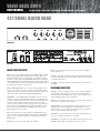
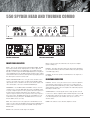
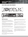
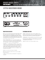
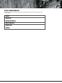
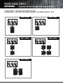
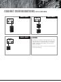
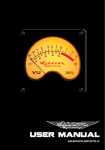
USER MANUAL
427 SMALL BLOCK • 550 SPYDER • 550 TOURING • BTA 200/300/400 • LITTLE BASTARD
VALVE BASS AMPS
USER MANUAL
427 SMALL BLOCK • 550 SPYDER • 550 TOURING • BTA 200/300/400 • LITTLE BASTARD
WELCOME TO ASHDOWN VALVE BASS AMPS
Thank you for choosing an Ashdown Valve Series amplifier. To ensure
that you receive the full benefits of the Ashdown warranty, please
register your amplifier at www.ashdownmusic.com
protect the finish and, if you are transporting it with other equipment, make
sure that the amplifier is on a solid floor at the bottom of the pile.
WARRANTY
Amplifiers are heavy. Take care when lifting, always use the handles fitted to
the amplifier to move it, and get help if you have to lift the amplifier to a
greater height than you feel comfortable with.
Your amplifier is covered by a one year warranty, against defects in materials
and workmanship, for the original purchaser. Ashdown will, at their discretion,
replace or repair any product or part thereof, which is found by Ashdown to
be defective. This warranty shall not apply to the damage of covering, fittings
or finishes when affected by carelessness, accident or extreme climate
changes. Nor does it apply to normal wear and tear of parts such as valves,
fuses, light bulbs, speakers, controls etc.
In the unlikely event of any defect, please contact an authorised Ashdown
dealer. All transport charges are to be pre-paid by the Owner. Unless your
purchase is registered on-line, normal country warranty laws apply.
IMPORTANT SAFETY
INSTRUCTIONS
This Ashdown amplifier has been designed to provide you with many
years of faithful service – on the road, in a studio or in a domestic
environment. By following the rules set out below, you will ensure that
the unit functions safely.
Valve (tube) instrument amplifiers contain very high voltages and fragile glass
tubes and should therefore be handled with care. A number of important
precautions which must be observed are set out below.
Before using the amplifier, run through the check list below. If you are in any
doubt about any aspect of the amplifier’s operation, stop using it immediately
and do not resume operation until the amplifier has been thoroughly
inspected by a qualified technician.
1) Storage and moving
When your amplifier is not in use make sure that the power cord is
unplugged from the mains outlet, and that all leads are removed from the
amplifier, including jack leads and footswitch leads. Jack socket connectors
are self-cleaning, so the process of plugging in and unplugging the leads
when not in use will ensure that the internal contacts will be cleaned when
you plug in again.
Store your amplifier in a warm, dry place away from moisture and
condensation. A motor vehicle or cellar may look dry but condensation can
form inside the unit causing short circuits and possible electric shock. If you
suspect the amplifier may have become exposed to moisture, move it to a
warm dry place and leave it to dry out for at least 48 hours before attempting
to use it.
Condensation can also occur when you move the amplifier from a hot humid
place (such as a nightclub) to a cold place (like a motor vehicle). In such
instances, always move the amplifier into a warm dry room to prevent
damage.
When moving the amplifier, handle it as carefully as you would your
instruments. Although solidly built, an amplifier is easily damaged by shock,
so be careful not to drop it or allow it to fall over. Use a protective cover to
Never attempt to operate the amplifier after it has been dropped. Take it to a
qualified technician and have it checked before using it again.
2) Leads and plugs
Your amplifier contains possibly lethal voltages and must therefore be connected
to the mains using the correct power cord, which is a three terminal type with a
ground connection.
The power cord supplied with the unit should be of the correct type. If it does
not fit your mains outlet consult your dealer or a qualified electrician for
advice before attempting to use the amplifier.
Never modify the power cord or attempt to use it with a two pin outlet. Store
all your leads in a dry case and take care when packing them away. All leads,
including guitar leads, are easily damaged with careless handling, so it is a
good idea to carry a spare lead of every type you use. Flexible power cords
get damaged very easily. At the first sign of damage, discard it and purchase a
new one. Always replace the power cord with one of the same type. Moulded
cords are the best choice with both plugs permanently fitted to the cord.
When using your amplifier and other equipment it is a good idea to connect
to the supply using a unit known as an R.C.D. These units are not expensive
and offer the user additional protection against electric shock. An electrical
shop should be able to supply you with a suitable unit.
3) Before Use
Inspect your amplifier for damage before use. Check each lead for damage
before you plug them in to the amplifier, and ensure that the loudspeaker is
connected before you switch the amplifier on.
Never try to operate the amplifier without the speaker connected. If you do,
serious damage to the amplifier will result which will be very expensive to repair.
Double check the connections you have made to your amplifier and make
sure you have connected the speaker to the correct outlet socket that
matches the cabinet you are using. The impedance of the speaker is
important and is usually shown on a plate affixed to the back of the cabinet,
so if the cabinet is 16R (Ohms) then you plug into the 16R outlet on the
amplifier.
4) Using the amplifier
When you set the amplifier up for use, it is important that you adhere to the
following rules:
Place the amplifier away from sources of heat, including radiators, etc. The
amplifier itself will get hot in normal use.
Make sure that all the grilles on the amplifier are not obstructed in any way
so that cooling air can circulate through the amplifier. Do not place anything
on or behind the amplifier that might restrict the flow of air. This includes
items of clothing, or other equipment.
Do not place the amplifier in such a position where it may get splashed with
liquid or water, e.g. near tables of drinks or near equipment that contains
water, e.g. smoke and bubble machines
The lightning flash within a triangle is intended to alert the
user to the presence of un-insulated dangerous voltage within
the product enclosure that may be of sufficient magnitude to
constitute a risk of electric shock.
Never stand bottles or containers of liquid on the amplifier. If any liquid is
accidentally spilled into the amplifier, unplug it from the mains supply
immediately and take the amplifier to a qualified technician for inspection.
This highlights the
presence of dangerous
voltages within the
equipment enclosure.
Never try to operate the
unit out of the enclosure.
Do not place objects on the amplifier that could fall inside and cause a
malfunction, e.g. coins, tools, etc.
5) Sound level
The level of sound or ‘volume’ you choose to use will mainly be dependant
on the size of the room you are playing in and you should use the volume
level that gives you the desired results. Always operate the amplifier at the
lowest level you can in any given situation. Each room will have a sweet spot.
Play at too low a level and the instrument will not react with the amplifier, too
high and the instrument will be unplayable. In all cases you should use a
level that you feel comfortable with.
The Human ear is a very sensitive instrument and can easily be permanently
damaged by exposure to the high sound pressure levels that can be
produced by this type of amplifier. Do not operate for prolonged periods of
time at high volume without suitable ear protection, or at a level that causes
you discomfort in any way.
If you experience any hearing loss or ringing in the ears you should consult a
doctor or audiologist.
6) Fuses and ratings
Your amplifier is fitted with several fuses to protect yourself and the
expensive electronics inside from damage in the event of a malfunction
within the amplifier. The size and rating of the fuses bas been calculated to
offer the most protection from damage possible.
8) Grounding Instructions
This product must be grounded (earthed). If it should malfunction or break
down the grounding provides the path of east resistance for the electric
current, to reduce the risk of electric shock.
This product is equipped with a power cord which contains a grounding
conductor and a grounding plug. The plug must be plugged into a compatible
mains outlet that is properly installed and grounded in accordance with the
local electrical safety codes applicable to your country.
DANGER!! Improper connection of the grounding conductor can result in the
possibility of an electric shock. If you are in any doubt about the ground
connection check with a qualified electrician before using this product. NEVER
modify the mains power cord. Have a suitable mains outlet fitted!
The wires contained within the supplied power cord are colour coded as
follows:
GREEN & YELLOW – GROUND OR EARTH CONDUCTOR
BROWN – LlVE CONDUCTOR
BLUE – NEUTRAL CONDUCTOR
9) Other markings
Various circumstances can lead to fuse failure. It is recommended that you
familiarise yourself with the type and rating of the individual fuses fitted to
your amplifier and carry spare fuses clearly marked with you as
replacements.
Occasionally a fuse will fail as a result of a power surge in the supply or as a
result of incorrect connection of the loudspeaker. It is permissible to replace
the damaged fuse with one of the same type and rating as stated on the rear
panel of the amplifier, having first unplugged the amplifier from the mains
supply and allowed it to cool down. If the fuse keeps blowing this indicates
that there is a more serious fault within the amplifier such as a damaged
tube. In this event you must take the amplifier to a qualified technician for
repair.
Never fit a fuse larger than the recommended rating.
The fuses fitted to you amplifier are ‘Anti Surge’ or ‘Slow Blow’ or ‘Time
delay’ type fuses, and have the prefix T or H in the part number. So, for
example, a 5 Amp fuse would be T 5A H. The exact rating for each particular
fuse can be found next to the holder in which that fuse fits. If you are not
sure what to buy when purchasing replacements, take the amplifier with you
and show the rear panel to the retailer.
7) Warnings used on this equipment
The exclamation mark contained within a triangle is intended to
alert the user to important operating and servicing instructions
contained in the literature accompanying this product.
Other markings appear on the rear panel of the amplifiers as
follows: back of the amplifier has some other markings on it
as follows;
Directs you to recycle this product by taking it to a disposal
area for electronic waste when you have finished with it, and
not dispose of it in the normal household waste.
Indicates that the product contains only the permitted levels
of substances known to be hazardous to your health.
Indicates that the product has been constructed to European
Harmonised Standards and is intended to show that the
product is safe to use. At present, the manufacturer can selfcertify.
Relates to an independent safety testing laboratory and shows
that the product has been subjected to, and passed, a series
of safety and quality tests and indicates that the product
meets all the criteria for sale in Canada and the USA.
Note:
The CE mark attached to these products means it conforms to
EMC(89/69/EEC) ,(93/68/EEC) and LDV(72/23/EEC).
VALVE BASS AMPS
USER MANUAL
427 SMALL BLOCK • 550 SPYDER • 550 TOURING • BTA 200/300/400 • LITTLE BASTARD
427 SMALL BLOCK HEAD
FRONT PANEL
REAR PANEL
FRONT PANEL FACILITIES
INPUTS - There are two instrument inputs marked LOW and HIGH. The LOW
input is high sensitivity and also high impedance to suit the output from
PASSIVE (Low Output) basses. The HIGH input is low sensitivity and lower
impedance to suit the output from ACTIVE (High Output) basses. Plugging an
active (High Output) bass into the LOW input will overload the input, creating
a fatter, warmer and more distorted sound. Experiment by plugging your bass
into either input to achieve the desired sound.
EFFECTS SEND AND RETURN - These 1/4" jack sockets should be used to
connect to an external effects device or pedal board. The EFFECTS SEND
output should connect to the INPUT of the effects unit, and the output of the
effects unit should be connected to the EFFECTS RETURN input.
EQ CONTROLS - Use the MIDDLE, BASS and TREBLE controls to effect the
overall tone of the sound. The MID SHIFT switch causes the MIDDLE control
to operate on higher frequencies in the up position, and lower frequencies in
the down position. The BASS SHIFT switch causes the BASS control to
operate on deeper frequencies in the up position, and less deep frequencies
in the down position. The BRIGHT switch adds an overall brightness to the
sound when in the up position. (Note: The BRIGHT switch is not effective
when the GAIN control is set to full).
GAIN - This controls the level of the signal sent to the MASTER section. To
achieve a cleaner sound, turn the GAIN control down and the MASTER up. To
achieve a richer, more distorted sound, turn the GAIN control up and the
MASTER down.
MASTER - This controls the overall output of the amplifier.
MUTE - In the up position, this switch mutes the out put of the amplifier
(useful for tuning, etc.).
PRE/POST - This switch determines whether the signal from the DI OUTPUT
(see Rear Panel Facilities) is taken before/PRE the EQ section (down position)
or after/POST (up position).
VU METER - The VU meter provides a visual indication of the output level of
the amplifier.
REAR PANEL FACILITIES
DI OUTPUT - This 1/4" stereo jack socket is used to connect the amplifier to
a low impedance, balanced input on a PA system or recording mixer. The
signal can be taken PRE or POST EQ (see above), ie with or without the tone
shaping added by the EQ section of the amplifier.
LINE INPUT - This 1/4" jack socket is used to connect the output of line level
devices such as samplers and sound modules.
SPEAKER OUTPUTS - There are dedicated Speakon connectors for 2, 4 and
8Ω load speaker cabinet configurations. It is important that the correct
output or outputs are used to match the impedance load of your cabinets.
Please refer to the diagrams later in this manual.
OFF/PREHEAT - Use this switch to pre-heat the valves, bringing them up to
the correct operating temperature before performing.
STANDBY/FULL - No signal is sent to the speakers when this switch is in the
STANDBY position. Switch to FULL when you are ready to perform.
550 SPYDER HEAD AND TOURING COMBO
MIDDLE
INPUTS
LOW
HIGH
BASS
TREBLE
MASTER
GAIN
EFFECTS
SEND
RTN
MID SHIFT
BASS SHIFT
BRIGHT
MUTE
PRE POST
OUTPUT
FRONT PANEL
REAR PANEL (SPYDER HEAD)
REAR PANEL (TOURING COMBO)
FRONT PANEL FACILITIES
INPUTS - There are two instrument inputs marked LOW and HIGH. The LOW
input is high sensitivity and also high impedance to suit the output from
PASSIVE (Low Output) basses. The HIGH input is low sensitivity and lower
impedance to suit the output from ACTIVE (High Output) basses. Plugging an
active (High Output) bass into the LOW input will overload the input, creating
a fatter, warmer and more distorted sound. Experiment by plugging your bass
into either input to achieve the desired sound.
EFFECTS SEND AND RETURN - These 1/4" jack sockets should be used to
connect to an external effects device or pedal board. The EFFECTS SEND
output should connect to the INPUT of the effects unit, and the output of the
effects unit should be connected to the EFFECTS RETURN input.
EQ CONTROLS - Use the MIDDLE, BASS and TREBLE controls to effect the
overall tone of the sound. The MID SHIFT switch causes the MIDDLE control
to operate on higher frequencies in the up position, and lower frequencies in
the down position. The BASS SHIFT switch causes the BASS control to
operate on deeper frequencies in the up position, and less deep frequencies
in the down position. The BRIGHT switch adds an overall brightness to the
sound when in the up position. (Note: The BRIGHT switch is not effective
when the GAIN control is set to full).
GAIN - This controls the level of the signal sent to the MASTER section. To
achieve a cleaner sound, turn the GAIN control down and the MASTER up. To
achieve a richer, more distorted sound, turn the GAIN control up and the
MASTER down.
MASTER - This controls the overall output of the amplifier.
MUTE - In the up position, this switch mutes the out put of the amplifier
(useful for tuning, etc.).
PRE/POST - This switch determines whether the signal from the DI OUTPUT
(see Rear Panel Facilities) is taken before/PRE the EQ section (down position)
or after/POST (up position).
VU METER - The VU meter provides a visual indication of the output level of
the amplifier.
REAR PANEL FACILITIES
DI OUTPUT - This 1/4" stereo jack socket is used to connect the amplifier to
a low impedance, balanced input on a PA system or recording mixer. The
signal can be taken PRE or POST EQ (see above), ie with or without the tone
shaping added by the EQ section of the amplifier. The 550 Touring replicates
this facility on an XLR socket.
SPEAKER OUTPUTS - The 550 Spyder features a single Speakon connector
to connect to a cabinet configuration with a minimum impedance load of 4Ω.
The 550 Touring combo has two Speakon connectors, one of which connects
to the internal speaker, the other of which can be used to connect an
extention cabinet.
POWER - This switch is used to switch the amplifier on and off.
VALVE BASS AMPS
USER MANUAL
427 SMALL BLOCK • 550 SPYDER • 550 TOURING • BTA 200/300/400 • LITTLE BASTARD
BTA 200/300/400 HEADS
FRONT PANEL
REAR PANEL
FRONT PANEL FACILITIES
INPUTS - There is a single instrument input provided linked to a
PASSIVE/ACTIVE selector switch. The Passive input (switch out) is high
sensitivity and also high impedance to suit the output from PASSIVE basses.
The Active input (switch in) is low sensitivity and lower impedance to suit the
output from ACTIVE basses.
INPUT CONTROL - The INPUT control sets the signal level through the
preamp in conjunction with the INPUT LEVEL VU Meter. This is adjusted to
give a reading of 0VU on the meter for average playing dynamics with
occasional peaks into the red region. Please note that the setting of this may
have to be re-adjusted after modification of the EQ controls.
PUSH FLAT / SHAPE - With this button in its OUT position a fixed E.Q. is
superimposed on the preamp to give a bright but punchy character to the
sound. Pushing this button IN returns the preamp to a Flat frequency
response.
This function may also be controlled from a footswitch. For the footswitch to
operate this button must be in its OUT position.
VALVE DRIVE - This routes the signal either through a clean Solid State
amplification section (control on zero) or through a Dual Triode Tube
amplification/overdrive section in order to add either tonal character i.e.
warmth with the control set at 9 o’clock, a slight edge in the sound at 12
0’clock through to an increasing degree of Tube distortion/overdrive as the
control is advanced to maximum.
A Mix of these two amplification sections can be achieved with this control.
N.B. The degree of tube distortion provided by this control will also depend on
the setting of the INPUT control.
VALVE DRIVE IN/OUT - This push button switches the valve drive section IN or
OUT. This function may also be controlled from the Ashdown 4 way
footswitch. For the footswitch to operate this button must be in its OUT
position.
E.Q. IN / OUT - This push button switches the Equalisation section IN or OUT
i.e. the Bass, Middle and Treble controls plus the two sets of sliders placed
between each of these.
This function may also be controlled from the Ashdown 4 way footswitch. For
the footswitch to operate this button must be in its OUT position.
EQ CONTROLS - These consists of BASS, MIDDLE and TREBLE controls with
two sliders placed between each control. These can be used in a number of
ways:
Firstly as a very simple Bass, Middle and Treble tone control section as found
on older traditional amplifiers. This is done by leaving the two sets of sliders
interposed between these controls set in their centre positions and using only
the BASS, MIDDLE and TREBLE controls to alter the overall tone.
Secondly, if more control is required then the sliders can also be used to
tailor the E.Q. in the regions between the main tone controls.
This provides a very versatile Equalisation section, it is simple to understand
and operate, yet provides a wide degree of variation. It retains the simplicity
of a three-control tone section but provides the flexibility of a graphic
equaliser.
COMPRESSION – Adding a small amount of compression gives a fat bottom
end to the sound and allows a greater volume of amplification to be used
without the playing peaks distorting the amplifiers output stage.
You will also find that this will add definition to your playing bringing out
notes within a run more clearly as it evens out the dynamics of your playing.
A large amount of compression can be used as an effect but it will tend to
reduce the dynamics in your playing to such an extent that the volume of the
note will be the same no matter how hard or soft you hit the string.
Compression also adds sustain to notes making them longer before they die
away.
The Compression Level control adjusts the degree of compression applied to
the bass signal. For this to function correctly the Input Level must be
correctly set as described in the INPUT CONTROL section (left).
When the Input Level is correctly set there will be hardly any difference in
volume between Compression IN and Compression OUT. This is because the
amplifier automatically compensates for the reduction in level that would be
apparent when Compression is added by increasing the overall gain to
restore the volume to its pre compression level, because of this you may
notice an increase in background noise with high compression settings.
COMPRESSION IN/OUT – This push button switches the Compression IN or
OUT. This function may also be controlled from the Ashdown 4 way
footswitch. For the footswitch to operate this button must be in its OUT
position.
SUB HARMONICS - This section produces Sub Harmonics an octave below
the notes being played. The level of these Sub Harmonics relative to the
straight bass sound can be adjusted using the LEVEL control.
This is very effective in thickening the sound and you will find in use that only
a small degree of this lower octave is required to really fill out the sound and
provide a character that is not possible by any other means.
i.e. pressing this button mutes all sound from the amplifier and allows a tuner
connected to the TUNER socket to operate for silent tuning. Release the
button and you are back in action again.
TUNER OUT - This output socket provides a line level signal that can be used
for a permanent connection to a tuner.
The signal from this socket remains when all other outputs from the amplifier
are Muted allowing all sound from the amplifier to be silenced while tuning is
in progress.
LINE OUT -This output socket provides a line level/post Output Level control
signal for connection to an external power amplifier driving additional speaker
cabinets.
OUTPUT LEVEL - The OUTPUT control adjusts the overall level of the
amplifier. Adjust this for your preferred overall stage playing volume.can be
produced by this type of amplifier. Do not operate for prolonged periods of
time at high volume without suitable ear protection, or at a level that causes
you discomfort in any way.
REAR PANEL FACILITIES
LINE INPUT - The rear panel has a Line Input socket for connection of other
signal sources into the system. This can be used for plugging a CD, Tape or
MP3 player into the amplifier for practising, rehearsing or for connection of a
second pre-amp into the system.
EFFECTS SEND / RETURN - A serial effects loop is provided at a level of 0dB.
The EFFECTS SEND socket can also be used as a Line Out socket if required
as the signal path through the preamp is only broken when a jack plug is
inserted into the EFFECTS RETURN socket.
The EFFECTS SEND is situated after the EQ, the Valve section the
Compression and the Sub Bass Processor.
The degree of Sub Harmonics is also dependant on the setting of the BASS
control.
DIRECT INJECT (D.I.) - A balanced D.I. is provided on a latching XLR socket.
This has a push button placed below it that allows the user to choose either
a Pre E.Q. signal (button pushed IN) or a Post E.Q. Post Sub and effects
signal (button OUT).
4-WAY FOOTSWITCH SOCKET - For the 4 way footswitch to operate it is
essential that the corresponding front panel push buttons be in the OUT
position. This is a mono jack socket for connection of the supplied Ashdown
4 way footswitch only.
The output signal from this XLR socket is set to a level and impedance
suitable for connecting directly into the Microphone input of a mixing desk for
either Direct Injection into the PA system or for recording. This must ONLY be
used into a Balanced Microphone input, it is not intended for any other type
of connection.
Always connect this prior to turning on the power to the amplifier as the
footswitch derives its power from the amplifier and sends a serial data
stream to the amplifier in order to operate the various functions.
Each of the 4 facilities available for selection is indicated by an LED that will
light when that facility is selected from the footswitch.
This has a floating ground that is referenced to the mixing console it is
plugged into and should not need ground lifting. It is also unaffected by
Phantom Powering on the Microphone input.
SPEAKER OUTPUTS - There are dedicated Speakon connectors for 2, 4 and
8Ω load speaker cabinet configurations. It is important that the correct
output or outputs are used to match the impedance load of your cabinets.
Please refer to the diagrams later in this manual.
Make sure your XLR plug does not have the shell of the plug internally
connected to signal ground or this will connect the system to chassis ground
of the ABM and may cause problems with hum.
PUSH TO MUTE - When pushed IN this button mutes the output from the
preamp to the power amp, mutes the output from the D.I. socket and mutes
the output from the LINE Out socket as well. This leaves the output from the
TUNER socket still available to allow muted tuning. An LED is provided next to
this switch to indicate when the amplifier is muted. This function operates
only from the front panel MUTE push switch.
OFF/PREHEAT - Use this switch to pre-heat the valves, bringing them up to
the correct operating temperature before performing.
STANDBY/FULL - No signal is sent to the speakers when this switch is in the
STANDBY position. Switch to FULL when you are ready to perform.
VALVE BASS AMPS
USER MANUAL
427 SMALL BLOCK • 550 SPYDER • 550 TOURING • BTA 200/300/400 • LITTLE BASTARD
LITTLE BASTARD HEAD
FRONT PANEL
I
o
REAR PANEL
FRONT PANEL FACILITIES
REAR PANEL FACILITIES
INPUTS - There are two instrument inputs marked LOW and HIGH. The LOW
input is high sensitivity and also high impedance to suit the output from
PASSIVE (Low Output) basses. The HIGH input is low sensitivity and lower
impedance to suit the output from ACTIVE (High Output) basses. Plugging an
active (High Output) bass into the LOW input will overload the input, creating
a fatter, warmer and more distorted sound. Experiment by plugging your bass
into either input to achieve the desired sound.
DI OUTPUT - This XLR socket is used to connect the amplifier to a low
impedance, balanced input on a PA system or recording mixer. The DI output
is taken from a separate winding on the output transformer, allowing the full
character of the valve tone to be sent to the PA or recording console.
EFFECTS SEND AND RETURN - These 1/4" jack sockets should be used to
connect to an external effects device or pedal board. The EFFECTS SEND
output should connect to the INPUT of the effects unit, and the output of the
effects unit should be connected to the EFFECTS RETURN input.
EQ CONTROLS - Use the MIDDLE, BASS and TREBLE controls to effect the
overall tone of the sound. The MID SHIFT switch causes the MIDDLE control
to operate on higher frequencies in the up position, and lower frequencies in
the down position. The BASS SHIFT switch causes the BASS control to
operate on deeper frequencies in the up position, and less deep frequencies
in the down position. The BRIGHT switch adds an overall brightness to the
sound when in the up position.
MASTER - This controls the overall output of the amplifier.
MUTE - In the up position, this switch mutes the out put of the amplifier
(useful for tuning, etc.).
VU METER - The VU meter provides a visual indication of the output level of
the amplifier.
SPEAKER OUTPUTS - There are dedicated 1/4" jack connectors for 4 and 8Ω
load speaker cabinet configurations. It is important that the correct output or
outputs are used to match the impedance load of your cabinets. Please refer
to the diagrams later in this manual.
POWER - This switch is used to switch the amplifier on and off.
RECORD YOUR INFORMATION
You should us this space to record all the important information off the rear panel of your amplifier for
future reference.
MODEL:
SERIAL NO:
DATE OF PURCHASE:
SUPPLY VOLTAGE:
MAINS FUSE:
HTFUSE:
VALVE BASS AMPS
USER MANUAL
427 SMALL BLOCK • 550 SPYDER • 550 TOURING • BTA 200/300/400 • LITTLE BASTARD
CABINET CONFIGURATIONS 427 SMALL BLOCK / BTA
SINGLE 4Ω CABINET
SINGLE 8Ω CABINET
DUAL 8Ω CABINETS
QUAD 8Ω CABINETS
DUAL 4Ω CABINETS
CABINET CONFIGURATIONS LITTLE BASTARD
SINGLE 4Ω CABINET
SINGLE 8Ω CABINET
DUAL 8Ω CABINETS
WARNING
Ashdown BTA, 427 Small Block and Little Bastard bass amps feature
valve output stages. It is therefore important to connect the speaker
cabinet(s) correctly before switching the amplifier on. Switching the
amplifier on without the speaker cabinet(s) connected can cause
damage to the amplifier.
Damage caused by the failure to correctly connect speaker cabinets is
not covered under warranty.
WWW.ASHDOWNMUSIC.COM