1
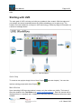
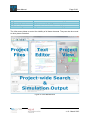
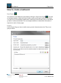
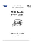
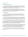
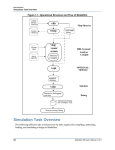
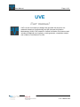
User Manual
Page: 1/26
UVE
User manual
UVE is a tool and a library to design and generate the structure of a
testbench based on SystemVerilog and the Universal Verification
Methodology (UVM). UVE stands for Unified Verification Environment and
includes a graphical user interface, a code generator, compilation scripts
and a library of verification IPs (VIP).
v1.0 - March 2013
User Manual
Page: 2/26
INSTALLING UVE ............................................................................................................................................... 3
Requested environment.................................................................................................................................. 3
Download the latest version ........................................................................................................................... 3
Installing UVE ................................................................................................................................................. 3
Support / Bug ................................................................................................................................................. 3
STARTING WITH UVE ........................................................................................................................................ 4
Quick Step ....................................................................................................................................................... 4
Main Window ................................................................................................................................................. 4
HOW TO CREATE A TESTBENCH ........................................................................................................................ 6
New Project
........................................................................................................................................... 6
Project ............................................................................................................................................................ 6
Signals ............................................................................................................................................................ 8
Environment ................................................................................................................................................. 10
HOW TO ADD A VERIFICATION COMPONENT ................................................................................................. 12
HOW TO LOAD AN EXISTING VC ................................................................................................................................ 12
HOW TO CREATE A NEW VC ..................................................................................................................................... 12
New Verification Component ....................................................................................................................... 13
New Agent .................................................................................................................................................... 15
HOW TO USE THE VIP LIBRARY ....................................................................................................................... 16
HOW TO INTEGRATE A VIP FROM THE LIBRARY INTO A TESTBENCH ................................................................................... 16
VIP connections ............................................................................................................................................ 16
HOW TO INTEGRATE A NEW VIP INTO THE LIBRARY ....................................................................................................... 17
Structure ....................................................................................................................................................... 17
uvc-File ......................................................................................................................................................... 17
HOW TO COMPLETE YOUR TESTBENCH .......................................................................................................... 24
Using the Project View.................................................................................................................................. 24
Using the Project Files .................................................................................................................................. 25
Using the Project Wide Search ..................................................................................................................... 25
Using the File Editor...................................................................................................................................... 25
HOW TO SIMULATE
............................................................................................................................... 26
IN UVE ................................................................................................................................................................ 26
IN SIMULATOR....................................................................................................................................................... 26
v1.0 - March 2013
User Manual
Page: 3/26
Installing UVE
Requested environment
UVE itself runs on Windows and Unix. To be able to simulate the generated TB the Questa®
Simulator 1 version 10.1 or newer from Mentor Graphics® 2 is needed.
Download the latest version
The latest version can be downloaded from http://www.systemverilog.ch/downloads/ or GitHub
with the following links:
−
−
−
https: https://github.com/uve-project/uve
ssh: [email protected]:uve-project/uve.git
read-only: git://github.com/uve-project/uve.git
Installing UVE
Windows
Execute the downloaded installer. During the installation process you can choose between a
normal installation and a portable one. The normal installation will place a shortcut on the
desktop and in the start menu for easy access. The portable installation only extracts the
program to the specified folder. This is meant for installation on removable devices like
memory sticks.
Linux
TBC
Support / Bug
Please fill in the contact sheet in http://www.systemverilog.ch/contact/ to get support or place a
bug report.
1
http://www.mentor.com/products/fv/questa/
2
www.mentor.com
v1.0 - March 2013
User Manual
Page: 4/26
salm
Starting with UVE
The main goal of UVE is to help you build your testbench from scratch. With the toplevel of
your design and some knowledge about the UVM methodology you’re ready to go. The
creation of a new testbench, or project in UVE terminology, is done by filling in information on
a series of message boxes.
Figure 1: UVE Workflow
Quick Step
To create a new project simply click on New Project
load an existing project with Open Project
(see next chapter). You can also
.
Main Window
Upon launching UVE the main window is empty; only the toolbars are visible. The heart of
the main window is the Text Editor (see Figure 2: UVE Mainwindow ). Each file opened will be
displayed here in a separate tab. In addition the following elements display themselves when
needed.
v1.0 - March 2013
User Manual
Project Files
Project View
Project-wide Search
Simulation Output
Page: 5/26
Tree view of all files used in the current project
Graphical view of the project
Search text in all files of the current project
Output of the simulation of the current project
The View menu allows to control the visibility of all these elements. They can also be moved
to other places if desired.
Figure 2: UVE Mainwindow
v1.0 - March 2013
User Manual
Page: 6/26
How to create a testbench
New Project
The creation of new testbench is launched by clicking on Project New Project
. A series
of message windows, called the Project Creator, guide you through creating a new project.
You have to fill in all mandatory fields before continuing to the next step, but you can always
go back to modify entered data. The next chapters describe in detail which information is
expected on each of these pages.
Project
On the Project Page you have to define some general information about the TB your are
going to create.
v1.0 - March 2013
User Manual
Page: 7/26
Figure 3: Project Creator Project Page
Field
Description
Notes
Project Name
Give your project a name
Mandatory
Project Folder
Folder where your project will be
generated
Mandatory
Simulator Path
The path to the simulator, e.g.
Optional, but mandatory if you
C:/mentor/questasim64_10.1c/win6 like to compile from UVE or with
4
the generated scripts
Templates Path
The path to the templates, normally Mandatory, normally no need to
there are no modifications needed change
VHDL Files
Add your DUV files in the order of
compilation
At least one file with the DUV
toplevel is mandatory.
DUV Toplevel
Select the DUV toplevel
The list gets populated with all
entities found in the VHDL files
Table 1: Project Creator Project Page
v1.0 - March 2013
User Manual
Page: 8/26
Signals
The behavior of Clock and Reset signals can be defined on this page.
Figure 4: Project Creator Signals Page
v1.0 - March 2013
User Manual
Page: 9/26
Field
Description
Notes
Signals
Lists all signals found in the
DUV
You can modify the usage, at least
one clock and one reset should be
defined
Signal Settings Defines how UVE will generate
clock and reset signals in the
testbench
You have to select a signal used as
clock or reset to be able to modify
something here
Table 2: Project Creator Signals Page
v1.0 - March 2013
User Manual
Page: 10/26
Environment
The Environment Page is there to define the structure of your TB and to add Verification
Components.
Figure 5: Project Creator Environment Page
v1.0 - March 2013
User Manual
Page: 11/26
Field
Description
Test Case Name
Name your testcase
Testbench name
Name your testbench
Testbench modules
Select the needed
modules
Verification Components Add VCs
Notes
The Scoreboard cannot be
deselected
see How to add a Verification
Component
Table 3: Project Creator Environment Page
v1.0 - March 2013
User Manual
Page: 12/26
How to add a Verification Component
One intention of UVM is to increase the reusability of VIPs. UVE makes it even easier for you
to integrate an existing VIP into your new verification environment. On the Environment page
of the Project Creator you are asked to add VCs. Currently there are two ways to do so. You
load an existing VIP from the library (see Load VIP) or you create a new VC according to your
needs (see New VC).
How to load an existing VC
Please refer to chapter How to integrate a VIP from the library into a testbench.
How to create a new VC
On the Environment page of the Project Creator click on Add new. This will open the New
Verification Component Page. Once you finished setting up your VC, it will appear on the list.
You can double click it there to review your settings.
v1.0 - March 2013
User Manual
Page: 13/26
New Verification Component
On this first page you can set some general information of your new VC, select the needed
modules and interface connections and Add new or remove agents. Added agents are
shown in a list, where you can set the number of instantiations of that agent.
Figure 6: Project Creator New Verification Component Page
v1.0 - March 2013
User Manual
Page: 14/26
Field
Description
Notes
Verification Component’s
Name
Name your verification
component
The name you provide is
checked to be unique
amongst Verification
Components
Description
Short description
Increases reusability
Modules
Select the needed modules
Some modules only become
selectable if others are
selected
Interface Connections
Select the DUV interface
connections
All DUV signals are listed,
Agents
Add agent to your VC
At least one agent
Table 4: Project Creator New Verification Component Page
v1.0 - March 2013
User Manual
Page: 15/26
New Agent
For new agents you can select the generated modules.
Figure 7: Project Creator New Agent Page
Field
Description
Notes
Agent’s Name
A meaningful name
The name you provide is
checked to be unique
amongst Agents in the
current Verification
Component. You can use
the same name in another
VC
Modules
Select the needed modules
Some modules only become
selectable if others are
selected
Table 5: Project Creator New Agent Page
v1.0 - March 2013
User Manual
Page: 16/26
How to use the VIP library
The VIP library is the place to store your VIPs. When you build a new TB it’s easy to reuse
one of these VIPs. For UVE a VIP is qualified when there is valid XML description of that
VIP. For VIPs created with UVE the XML description is already generated. For other VIPs
you have to write it on your own. For more details see How to integrate a new VIP into the
library.
How to integrate a VIP from the library into a testbench
After clicking Load existing on the Environment page you have find the XML description file
.uvc of the VIP you like to load. Once thats done, you have to connect it to the DUV with the
help of the VIP connections page.
VIP connections
Here you connect a loaded VIP with the DUV. To do so, select a signal on the left panel and
a signal on the right panel and click on Connect.
Figure 8: Project Creator VIP Connections Page
v1.0 - March 2013
User Manual
Page: 17/26
How to integrate a new VIP into the library
Adding your verification IPs (VIP) to the UVE library is quite straightforward. Basically you
only need to put the files in a compatible folder structure and add a file describing the VIP
and you’re done. Below there is a description of the folder structure and the description file’s
content.
Structure
Each VIP has to be placed in a separate folder. This folder has at least to contain the
description file. Other files or folders like license, documentation, examples, … can also be
placed in that t folder.
The all System Verilog (SV) source files have to be placed in separate folder. Furthermore
the source files of each Agent should also be placed in a separate folder. We recommend a
structure like in Figure 8.
Figure 8: UVE VIP Folder Structure
uvc-File
The uvc-File describes the structure of a VIP. It’s written in XML and used by UVE to display
information about the VIP and to copy it correctly to the generated TB. In general the XML
structure follows the structure of a UVM testbench. For each element of the TB, the name of
the element as well as the name of the corresponding file(s) must be given. Thereby UVE
differentiates between header files, body files and other files. Below is a complete structure
with all possible elements. Without indication an element is mandatory and can exist only
once. In the library directory of UVE there exists a uvc.xsd file that you can use to
automatically validate your uvc-File.
●
root
○
vip (version)
■
generated (true or false)
■
shortName (optional)
■
className
■
svdir (relative path to the SV source)
■
description
■
headerFile (zero or one)
v1.0 - March 2013
User Manual
Page: 18/26
■
bodyFile
■
otherFile (zero or more)
■
components
●
agent
○ shortName
○ instName
○ className
○ headerFile (zero or one)
○ bodyFile
○ otherFile (zero or more)
○ tlmports
○ fakeports
○ components
■ collector
●
shortName
●
instName
●
className
●
headerFile (zero or one)
●
bodyFile
●
otherFile (zero or more)
●
tlmports
○
●
tlmport
■
className
■
name
fakeports
○
fakeport
■
className
■
name
■ configuration
v1.0 - March 2013
User Manual
Page: 19/26
●
shortName
●
instName
●
className
●
headerFile (zero or one)
●
bodyFile
●
otherFile (zero or more)
■ driver
●
shortName
●
instName
●
className
●
headerFile (zero or one)
●
bodyFile
●
otherFile (zero or more)
●
tlmports
○
●
tlmport
■
className
■
name
fakeports
○
fakeport
■
className
■
name
■
direction
■ monitor
●
shortName
●
instName
●
className
●
headerFile (zero or one)
●
bodyFile
●
otherFile (zero or more)
v1.0 - March 2013
User Manual
Page: 20/26
●
tlmports
○
tlmport
■
className
■
name
■ sequencer
●
shortName
●
instName
●
className
●
headerFile (zero or one)
●
bodyFile
●
otherFile (zero or more)
●
tlmports
○
tlmport
■
className
■
name
○ connections
■ connection
●
name
●
srcPort
●
dstPort
○ nbAgents
○ svdir
●
configuration
○ shortName
○ instName
○ className
○ headerFile (zero or one)
○ bodyFile
○ otherFile (zero or more)
v1.0 - March 2013
User Manual
Page: 21/26
●
interface
○ shortName
○ instName
○ className
○ headerFile (zero or one)
○ bodyFile
○ otherFile (zero or more)
○ fakePorts
■ fakePort
● className
● name
● direction
○ physicalPorts
■ port
● name
● mode
● direction
● category
● size
● frequency
● monitor
○ shortName
○ instName
○ className
○ headerFile (zero or one)
○ bodyFile
○ otherFile (zero or more)
○ fakePorts
■ fakePort
v1.0 - March 2013
User Manual
Page: 22/26
● className
● name
● direction
●
package
○ shortName
○ instName
○ className
○ headerFile (zero or one)
○ bodyFile
○ otherFile (zero or more)
●
scoreboard
○ shortName
○ instName
○ className
○ headerFile (zero or one)
○ bodyFile
○ otherFile (zero or more)
○ tlmports
■ tlmport
● className
● name
●
sequence
○ shortName
○ instName
○ className
○ headerFile (zero or one)
○ bodyFile
○ otherFile (zero or more)
●
sequenceitem
v1.0 - March 2013
User Manual
Page: 23/26
○ shortName
○ instName
○ className
○ headerFile (zero or one)
○ bodyFile
○ otherFile (zero or more)
●
virtualsequencer
○ shortName
○ instName
○ className
○ headerFile (zero or one)
○ bodyFile
○ otherFile (zero or more)
○ tlmports
■ tlmport
● className
● name
■
connections
●
connection
○
name
○
srcPort
○
dstPort
v1.0 - March 2013
User Manual
Page: 24/26
How to complete your testbench
Once you’ve generated the structure of your TB with UVE, you have to fill in the gaps. The
places that are intended to be completed are marked with a @TODO in the files. There is
also some helpful text to guide your completion steps. All these places can easily be found
by opening the Project-wide search (Ctrl+Shift+F) and click on the static search button
TODO.
A summary of all todos is also given in the TODO.txt file in your project folder.
Using the Project View
The project view offers a graphical representation of your testbench, allowing easy and
intuitive access to the different components of your project. Left-clic on a component
highlights it in green, and opens its System Verilog body file. Accessors for the other
available files are added in the top right corner. Here is a table of all possible accessors.
Accessor name
Description
Header File Accessor
Greyish blue circle, with “h”
inscription
Configuration File Accessor
Greyish blue circle, with “c”
inscription
Package File Accessor
Greyish blue circle, with “p”
inscription
Sequence Item Accessor
Greyish blue circle, with “si”
inscription
Sequence Accessor
Greyish blue circle, with “s”
inscription
Other Files Accessor
Greyish blue circle, with “o”
inscription
Notes
As more than one other file
may be present, clicking on
this accessor opens a
contextual menu, offering
access to all available files.
Table 6: File Accessors
v1.0 - March 2013
User Manual
Page: 25/26
Furthermore, you can add files to existing components, by right-clicking on it, and selecting
add file… in the contextual menu. All files added that way are included in the other files list,
and therefore can be found in the corresponding accessor.
Using the Project Files
The Project files offer a direct access to files in a classic tree view. However, the tree is built
to match the testbench’s structure, not the actual folder / files tree on your disk.
For instance, the tree has two main roots, Testbench and DUT. DUT obviously contains all
VHDL files describing your Device Under Testing. Testbench contains all System Verilog
files that were generated. Testbench level files are accessible directly under Testbench, and
Verification Components (both custom created and loaded) files are organized in
corresponding folders (one for each VC), under the VIP branch. Currently active file is
highlighted in the tree view.
Using the Project Wide Search
The Project Wide Search offers convenient way to find expressions in all files of the current
project. The first part of the view offers classic dynamic searches, both with text (with
optional case sensitivity) and regular expressions. When searching for text, you can also
replace it, by filling the corresponding field, and selecting the replace mode (one occurrence
at a time, every occurrence in current file or every occurrence project wide).
The second part offers static search. A permanent TODO static search is already present,
and allows for quick access to the places you need to edit in order to personalize your
testbench. But if you are constantly searching for a specific term, your can create your own
static search buttons, by clicking on the + button, right from the TODO static search. Note
that personalized static searches can be deleted by clicking on the x part of the button.
The last part show all results of the latest search. Each line represent a result, and details the
name of the file, the line number and the actual text in which the sought text was found.
Using the File Editor
Most importantly, the text editor is your main work space, and as such, we made sure you
were provided with all the necessary features.
A tabbed view of all opened files allows easy access to every part of your current work. You
can easily switch between file by using these tabs, or alternatively, by using either the Project
View or the Project Files view. You can close tabs by clicking on the cross, and reorganize
them with a simple drag-and-drop. When closing a tab that has been modified, you will be
prompted to save you changes, in order to ensure your work is not lost.
Advanced syntax coloring comes standard, giving you extra readability in every System
Verilog file. To improve even more readability, you can collapse the parts of code you don’t
need. Obviously, you can edit the files in any way you want.
v1.0 - March 2013
User Manual
Page: 26/26
How to simulate
To simulate a project you need to have set a valid path to a compiler on the Project page of
the Project Creator. Then you simply have to select the Simulate menu and choose the
way you like to simulate your design.
in UVE
When you select to simulate in UVE, the simulation is executed in console mode and the
output is shown in the Simulation Output panel. Once the simulation is finished, a message
will pop up with short notice with the exit code.
in Simulator
When you also need to see the waveform this option will start the simulation in GUI mode.
v1.0 - March 2013