1
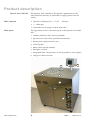
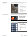
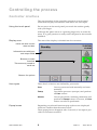
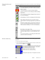
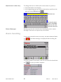
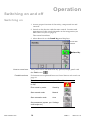
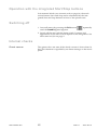
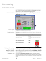
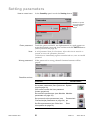
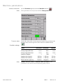
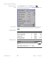
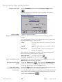
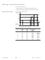
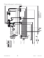
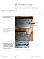
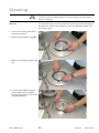
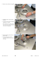
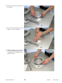
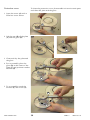
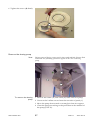
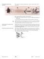
Spinner Unit LSM-200
User Manual
SAWATEC AG
SAWATZKI TECHNOLOGY
Industriestrasse 416, FL-9491 Ruggell
Product description
Spinner Unit LSM-200
Main features
The Spinner Unit LSM-200 is designed for application in the
semiconductor industry, in particular to apply photo resist on
wafers.
• Chuck for substrates of 1" - 6" (25 … 150 mm)
• 1 … 6000 rpm
• Controller for 10 recipes with 24 steps each
Main parts
The figure below shows the main parts of the Spinner Unit LSM200:
1 Cabinet (stainless steel, electro polished)
2 Spinner bowl with chuck (anodized aluminum)
3 Dosing arm with protective cover
4 Control panel
5 Main switch (inside cabinet).
6 Emergency switch
7 Integrated Start / Stop buttons work in parallel to touch panel
8 Gauge for chuck vacuum
4
3
6
2
8
7
1
5
www.sawatec.com
4
SAW-12
2005-09-19
Connectors and
appliances
Connectors are located at the bottom of the rear cabinet. Use the
supplied 8mm key to open and close the rear cabinet.
1 Compressed air intake.
Connects to P1 (1) at the
gauges panel.
2 Commpessed air intake
connecting to P2 (2) and
dosing air (3) at the gauges
panel.
3 Vacuum intake for the
chuck vacuum
1
3
2
4
4 Vacuum intake for dosing
pump. Connects to (4) at
the gauges panel.
5 Exhaust
6
Main switch and fuse
5
6 Mains intake 230 VAC
The main switch and the fuse is located to the bottom of the right
part of the front cabinet.
A blown fuse pops out. Before
pressing the fuse button to
activate it again, the reason for
the short circuit must be
removed!
To switch on turn the main
switch to the right.
Gauges panel
Pressure control and gauges are located in the right part of the
front cabinet.
The control valve is to the left,
the gauge to the right:
1
1 Compressed air for dosing
arm rotation and lifting of
the spash guard ring
2
2 Compressed air for ancillary use
3
4
www.sawatec.com
5
3 Compressed air for the dosing pump
4 Vacuum for the dosing
pump
SAW-12
2005-09-19
Technical data
Operational characteristics
Physical properties and
environment
Property
Nominal value
Chuck size
1…6" (25…150 mm)
Speed range
1…6000 rpm
Property
Nominal value
Width/depth/height
85 / 75 / 90 cm
Control panel height 30cm
Tolerance / specification
Specification
above working surface
Weight
110 kg
Electrical power
230 VAC, 50/60Hz Socket for 3-pin plug
15 A
C12
Control power
24 VDC, 5A
Vacuum
-0.8 bar ±0.1 bar
Fitting for hose Ø 4/
6 mm
Compressed air
> 4 bar
Fitting for hose Ø 4/
6 mm
Exhaust
20-50 m 3/h
Fitting for hose inner
Ø 76 mm
When positioning the Spinner Unit LSM-200 sufficient space for
the operator must be provided at the front side.To access the rear
te unit may be moved on its rollers.
For proper operation the Spinner Unit LSM-200 must be levelled
with screws near the bottom rollers.
Levelling screws
2
To move the spinner unit on
the rollers (1) the levelling
screws (2) must give clearance
of at least 5mm
1
Standards
The Spinner Unit LSM-200 uses only DIN-CE certified elements
or DIN-CE certified materials.
www.sawatec.com
6
SAW-12
2005-09-19
Controlling the process
Controller interface
The user interface of the controller comprises a touch panel
which both displays information and allows for user input.
Using the touch panel
Do not press on the touch panel, just touch the surface gently
with your finger.
Although the panel reacts to a pointing finger also in some distance, it is good practice to really touch the panel to have tactile
feedback.
Display area
The area of the display is divided into four sections:
Panel title with current
date and time
Information are with input
and output fields
Buttons to select
functions
This area may contain a
scroll bar
Buttons for options
User types
Popup boxes
Three levels of actions are defined by passwords:
User
Can run processes both manually and automatically.
Setup
Can define processes (receipts) and perform
all User actions.
Master
Can set passwords, machine parameters and
perform all Setup actions. Of course, all User
actions can also be performed.
Depending on selected functions pop-up boxes are displayed
which are smaller than the entire screen.
These popup boxes disappear after 5 seconds, if no input is provided or no button touched.
www.sawatec.com
9
SAW-12
2005-09-19
General buttons and
controls
The following buttons and controls are used in various dialogues
Button
Function
Exit any display with this button.
In a menu hierarchy you walk one step up (back).
Alarm is active.
Touch the button to open the Alarm display.
Cancel: Leave the current dialogue without setting
any values
OK: Accept the provided (changed) input values of
the current dialogue.
Acknowledge: Confirm a message with this button.
Help: Display help about the controller menus.
This function is currently supported only rudimentary.
123
Increment (upper button) or decrement (lower button) the value displayed between the two buttons.
The increment normally is 1, but not necessarily.
Scroll bars to the right of lists.
Touch the lower button to scroll forward in the list
Touch the upper button to scroll backward in the
list.
For a quick location you may drag the slider button
(touch and move the button).
Numeric data entry
To change the value in a field (such as the turning speed of the
spinner):
• Touch the field on the display.
• In the appearing pop-up enter the desired value and leave the
pop-up with the Exit button
.
The maximum and minimum value which may
be entered is displayed on top. The middle
line displays the current entry.
Remove the last entered figure
Reset value to 0, clear the entry
Accept the input value. The panel is not left.
www.sawatec.com
10
SAW-12
2005-09-19
Alphanumeric data entry
To change the text in a field (such as the name of a process):
• Touch the field on the display.
• In the appearing pop-up enter the desired text and leave the
pop-up with the Exit button
.
Entered text
Accept the input
value with Enter.
Remove the last
entered character
Status Messages
During a process the central area of the display shows status
messages. These do not require any user action.
Alarm handling
If user intervention becomes necessary, the alarm button flashes
red
. The alarm message is displayed after touching the
alarm button.
To get the details of the alarm, select it and touch the details button
www.sawatec.com
11
. A pop-up window appears:
SAW-12
2005-09-19
Alarm history
The alarm history contains all confirmed and not confirmed
alarms. It is entered from the Alarm display with the history button
Possible actions
Function
Touch button
Delete the complete history Waste bin
Attention: You are not
prompted to confirm the action
Filter display of messages: Filter
a popup window will appear
Sort messages:
A to Z
a popup window will appear
Filter alarm display
Filter - popup
Sort - popup
To select the desired filter, touch To sort according to your dethe appropriate button.
sire touch the appropriate button.
www.sawatec.com
12
SAW-12
2005-09-19
Setting up the Spinner Unit
Before operating the Spinner Unit LSM-200 it must be set up as
follows:
Level the Spinner Unit
The Spinner Unit must be levelled for proper operation, using a
level and the levelling screws near the transport rollers at the
bottom.
Note:
The levelling screws can eliminate unevenness of about ± 5mm.
Secure location
The Spinner Unit may vibrate during operation and hence must
be secured to stay in its location. The level screws act as stoppers
also.
Connect piping and mains
1 Connect the exhaust hose to the outlet in the rear.
2 Connect the vacuum to the corresponding intake.
3 Connect the compressed air to the corresponding intake
4 Supply electric power
www.sawatec.com
13
SAW-12
2005-09-19
Operation
Switching on and off
Switching on
1 Assure proper function of electricity, compressed air and
vacuum.
2 Switch on the device with the main switch. Location and
appearance of this switch depends on the integration (see
Main switch and fuse on page 5).
The control initialises.
3 After about 10 sec the Stand by panel displays:
Current date
and time
T Stand by
How to come here
This panel can be reached from any process/recipe panel with
the Exit button
Possible actions
.
For buttons not explained here see General buttons and controls on
page 13.
Function
Touch button
Display alarm (alarm button Alarm
is red)
Enter stand by mode
Stand by
Start manual mode
Manual
Start automatic mode
Auto
Set parameters (system, pro- Settings
cess/recipe etc.)
www.sawatec.com
14
SAW-12
2005-09-19
Operation with the integrated Start/Stop buttons
In Automatic Mode (see Automatic mode on page 16) the touch
screen buttons Start and Stop can be substituted by the integrated Start and Stop buttons in front of the spinner unit.
Switching off
1 Leave all menus by pressing the Exit button
until the Stand by panel appears.
repeatedly
2 Switch off the unit with the main switch. Location and
appearance of the main switch depend on the integration. See
Main switch and fuse on page 5.
Internal checks
Chuck vacuum
The spinner does not start if the chuck vacuum is lower than 0.4
bar. This situation is signalled by an alarm message on the touch
panel.
www.sawatec.com
15
SAW-12
2005-09-19
Processing
Automatic mode
Panel Automatic is the standard display during normal operation. In this mode the process/recipe is started either by a handling device or the integrated Start/Stop buttons.
How to come here
This panel can be reached from any Stand by panel with the
Automatic button
.
T
Output display
Possible actions
Last process/recipe and last selected chuck;
parameters of selected process/recipe
For buttons not explained here see General buttons and controls on
page 13
Function
Touch button
Select a process/recipe to be run Touch the field next to the label
Recipe
Select the chuck
Touch the field next to the label
Chuck
Start selected process
Start
Stop current process
Stop
Start manual mode
Manual
Display while running a
process/recipe
The parameters of the process/recipe are continually displayed.
For example the Segment number loops through the recipe steps.
Additional functions
during the process
During the automatic mode the buttons Pre-Dispense, Arm on/
off and Dispense on/off can be touched to perform the corresponding action.
Emergency stop
Pushing the Emergency Switch holds the vacuum until the
motor has stopped. Current state of the machine is kept, until the
alarm has been cleared. Then the machine enters the initial state
again.
www.sawatec.com
16
SAW-12
2005-09-19
Setting parameters
How to come here
In the Stand by panel touch the Setting button
.
Number of cycles
run so far with the
currently active
recipe.
Enter password
Touch the password field. An alphanumeric key pad appears to
enter the desired password. You confirm with the ENTER button
(seeSet passwords on page 27).
Note:
A valid password lasts for 15 minutes. After this time it must be reentered to access the parameter functions.
To block access immediately against unauthorised use, enter an invalid
password.
Wrong password
If the password is wrong, then all function buttons will be
greyed
Possible actions
Function
Reset counter of current process
Touch button
Reset
Set system parameters (see System set- System
tings on page 26).
Can not be set with the User password
(button greyed out)
Set machine parameters (see Machine Machine
parameters on page 22)
Process/reciSet process/recipe parameters (see
Process/recipe parameters on page 24) pe
Set Drive parameters (see Drive functions spinner on page 19)
www.sawatec.com
21
Drive
SAW-12
2005-09-19
Machine parameters
How to come here
Note:
To set a value
In the Parameter panel touch the Machine button
.
These parameters can only be set with the Setup password.
Touch the value field. In the pop-up numeric key pad enter the
desired value and accept the value with the confirm button
.
Possible settings
Value
minimum
maximum
typical
0s
10 s
1.5 s
Pump purge pulse time
0.1 s
20 s
0.3 s
Pump purge pause time
0.1 s
20 s
2.0 s
1
999
1
Needle Valve on time
-200 ms
+ 200 ms
133 ms
Needle Valve off time
-200 ms
+ 200 ms
155 ms
Motor direction (spinner)
Positive
Negative
Positive
Vacuum off delay
Number of purges
Note:
www.sawatec.com
Needle Valve on time and Needle Valve off time are two
parameters to be selected for the dispensing pump SPV-15.
22
SAW-12
2005-09-19
Drive parameters
How to come here
Note:
To set a value
In the Parameter panel touch the Drive button
.
These parameters can only be set with the master password according to the values of the drive motor.
Touch the value field. In the pop-up numeric key pad enter the
desired value and accept the value with the confirm button
.
Possible settings
Value
minimum
maximum
typical
Proportional Speed Gain
0
30000
460
Integral 1 Speed Gain
0
65535
235
Integral 2 Speed Gain
0
65535
460
Damping Gain
0
65535
0
Speed low pass filter
0
65535
47800
Anti-resonance filter
0
65535
1
Possible actions
Function
www.sawatec.com
Touch button
Save changed values with new drive
name
Files
Save changed values of current drive
Save
Load values of current drive
Load
23
SAW-12
2005-09-19
Process/recipe parameters
How to come here
In the Parameters panel touch the Process/recipe button
.
For the Spinner Unit LSM-200 a process/recipe may have 24
steps or segments.
Output display
Set up a process/recipe
Current segment number.
See Set up a process/recipe on page 30 for an example process/
recipe.
For each segment of the process/recipe specify time, speed and
whether dispensing is active or not:
Time
Touch the field and enter a numeric value in
seconds
Speed
Touch the field and enter a numeric value in
rpm
Dispenser
Press button D1 to activate the dispenser
during this segment.
The values of all segments are kept in storage and hence You
may freely change between the segments:
Next segment
Touch the up arrow
Previous segmentTouch the down arrow
Clear unneeded entries
Delete/obliterate unneeded segments by entering zero (use the
DEL button in the numeric key pad).
Store current process/
recipe
Touch the Files button
. This opens the Parameter files
panel (see Save/load parameter files on page 25). After entering a
name and description, touch the Save button.
Start work with a
sample process/recipe
Touch the Files button and select an appropriate process/recipe.
With the Load button you read the parameters.
Leave panel
Leaving the panel without saving the process/recipe parameters
keeps them only available for the current processing. Leave any
panel with the Exit button
www.sawatec.com
24
.
SAW-12
2005-09-19
Set up a process/recipe
A process/recipe consists of
• up to 24 segments of speed/duration/dispense values
• Machine parameters (the general settings for all recipes)
Example process/recipe
Process diagram (not to scale).
Speed [rpm]
4000
2000
1200
time [s]
0
Segment
1
2
3
4
5
6
7
Dispensing
This process/recipe has seven segments:
www.sawatec.com
Segment
Segment
Time
[s]
Process
time
[s]
1
1.2
1.2
1200
D1 off
2
3.8
5.0
1200
D1 on
3
0.5
5.5
2800
D1 off
4
1.0
6.5
2800
D1 off
5
0.5
7.0
4000
D1 off
6
1.5
8.5
4000
D1 off
7
0.4
8.9
0.0
D1 off
30
Speed at end Dispense
of segment
[rpm]
SAW-12
2005-09-19
www.sawatec.com
31
Vacuum
SAW-12
N2
4 bar
Valve ON
Dispense needle NC
Option
Magnetic valves
15-D-Sub
15
14
13
12
11
10
9
9
8
7
6
8
7
6
5
4
3
2
1
5
4
3
2
1
0.5 - 2 bar
Motor cable
Sensor connector
9-D-Sub
Emergency Switch
Compresed air
blue
black
white
brown
black
purple
red
white
brown
gray
white/yellow
yellow
green
Start
brown/green
brown
black
black
gray
pink
blue
white
blue
blue
blue
yellow
black
green
red
brown
E
Stop
white/green
P
brown
brown
blue
pink
Modul LSM-250
www.sawatec.com
SAWATEC AG
Functional scheme
2005-09-19
Maintenance
The Spinner Unit does not need special maintenance besides
cleaning of spinner, dosing system and (optional) dispensing
pump.
Update firmware
The controller firmware is stored on a memory element placed in
the housing of the touch panel. To exchange the firmware, follow
these steps:
1 Get access to the top of the
touch panel housing
2 Open the Philips screw fixing
cover lid
Philips screw
Cover lid
3 Lift the cover lid at the right
about 10 mm
(1/2 inch) and slightly pull the
lid to the right
4 Press the small button firmly
to eject the firmware module
5 Insert the new firmware module with the labelled side
away from the touch panel
display (press it in firmly)
Eject button
Firmware module
6 Insert the cover lid and fix it
with the Philips screw
www.sawatec.com
32
SAW-12
2005-09-19
Cleaning
:
Spinner
Danger!
Always switch off the Spinner Unit and unplug it from mains
before cleaning!
To clean the rings, chuck and the bowl, the rings and chuck must
be removed. You do not need any tools for this procedure. Follow these steps:
1 Assure the dosing arm (A) is
at home position.
2 Remove the adapter ring (B)
B
A
3 Remove the splash guard ring
(C)
C
4 Lift the chuck (D) vertically
with slight back and forth
turning movements out of the
snap mechanism.
D
www.sawatec.com
33
SAW-12
2005-09-19
5 Remove the collector ring (E).
E
6 Clean the parts with proper
solvent.
7 Clean the bowl (F) with gentle
splashes of solvent.
Be careful not to spill solvent
into the exhaust tubes (G) and
the chuck clamp (H).
G
F
H
8 After cleaning insert the collector ring.
9 When placing the chuck,
watch the index holes (I) and
bolts (J)
I
J
www.sawatec.com
34
SAW-12
2005-09-19
10 Insert the chuck vertically into
its clamp.
11 Pess the chuck firmly into the
clamp – it must snap in!
12 Add the splash guard ring (K)
and the adapter ring (L) to
complete the assembly of the
spinner bowl.
L
K
www.sawatec.com
35
SAW-12
2005-09-19
Protective cover
To clean the protective cover, disassemble it it into its main parts
and clean the plate and the glass.
1 Open the screw (A) with a
5mm hex screw driver.
A
2 Lift the arm (B) off the plate
(C) and the glass (D)
D
B
C
3 Clean and dry the plate and
the glass.
4 For re-assembly place the
glass (D) in the center of the
plate (C) and position it under
the arm (B).
B
D
C
5 To re-assemble watch the
notches (E) and screw (A)
A
E
www.sawatec.com
36
SAW-12
2005-09-19
6 Tighten the screw (A) firmly
A
Remove the dosing pump
Note:
Various types of dosing pumps can be integrated with the Spinner Unit
LSM-200. The following procedure applies to the SPV-15 dosing
pump.
B
C
A
To remove the dosing
pump
1 Remove the intake (A) and outlet (B) tubes from the pump
2 Unscrew the 2 Allen screws from the rear side of panel (C)
3 Move the pump downwards to untangle it from its support.
4 Clean the pump according to the procedure in the manual of
the pump (SVP-15).
www.sawatec.com
37
SAW-12
2005-09-19
Cartridge dispensing
system
The optional cartridge dispensing system comprises the following parts:
B
A
C
D
F
E
G
A Glass syringe 50 ml
B Cap with pressure tube connector R 1/8”
C Rebound suck back valve with LUER lock (D) and needle connector (E)
F Syringe holder (to be inserted into the dispense arm cup)
:
When handling the cartridge take care of the concave moulding
(G) with the glass-steel combination. Avoid any bending to the
syringe and always hold the syringe vertical.
Removing the syringe from
the mount
When removing the syringe from the holder (gentle turning and
pulling), do not hold the syringe at the cap, but at the glass body
itself. When holding the cap you might accidentally remove the
cap from the glass body.
Removing and applying cap
The bulge of the glass syringe has a flat portion (A). To remove
the cap from the syringe, turn it gentle until the open portion of
the cap (B) matches the flat portion of the syringe bulge (A).
Then pull the cap from the syringe.
B
www.sawatec.com
38
A
SAW-12
2005-09-19