1
In Experimental Robotics 3, Yoshikaswa, T., Myiazaki, F (Eds.),
Lecture Notes in Control and Information Sciences 200. Springer Verlag. pp. 297--309.
Design of a Hydraulic
Robot
Based on a Combinatorial
Shoulder
Mechanism
Vincent Hayward
C e n t e r for I n t e l l i g e n t M a c h i n e s , M c G i l l U n i v e r s i t y
3480 U n i v e r s i t y S t r e e t
M o n t r e a l , Q u e b e c , C a n a d a , H 3 A 2A7
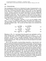
Abstract-- In previous papers, I have argued that while parallel mechanisms are
well known for their favorable structural properties, their utility is generally limited
by an inherently small workspace. I have also argued that proper use of actuator
redundancy can simultaneously increase the workspace, remove singularities, and
dramatically improve overall kinematic, structural, and actuator performance, while
keeping the complexity low. This paper discusses a prototype shoulder joint more
appropriately described as a combinatorial mechanism which exhibits the features.
Additional benefits in terms of modularity, self-calibration, reliability, self-test, and
degraded modes of operation are briefly discussed in the conclusion.
1. I n t r o d u c t i o n
While a great deal pf research activity is devoted to the design of robot manipulator wrists (see [18]) and articulated hands, the design of other joints or groups
of joints is not less challenging. A robot manipulator, like most technological
creations: automobiles, airplanes, excavators, etc., is an integrated machine.
Weakness of any of its constituents: actuators, sensors, structural properties,
materials, kinematic properties, dynamic properties, control techniques, and
many more factors, will affect dramatically the performance of the complete
machine [5].
Note that the great majority of existing manipulator arms, man-made or
found in Nature, can be viewed as the assembly of three joint groups: the shoulder group which provides for the overall orientation or the pointing direction of
the manipulator, the elbow group which provides for radial extension or reach,
and the wrist group which provides for the final orientation of the effector. Of
course, there are exceptions to this rule: some crustacean or insect limbs, for
example, are not so clearly organized. This rule nevertheless appears to be well
enforced for all larger animals.
Among man-made manipulators in use in the manufacturing industry (welding, painting, assembly, part handling, deburring, polishing, etc.), the author
has seldom seen an exception to this rule. In the application of robotics for intervention in remote or hazardous locations, this rule seems to be followed even
more meticulously: for undersea, outerspace, and other applications, among
many existing or proposed designs that the author has surveyed, the only ex-
In Experimental Robotics 3, Yoshikaswa, T., Myiazaki, F (Eds.),
Lecture Notes in Control and Information Sciences 200. Springer Verlag. pp. 297--309.
298
ception found are the "variable truss manipulators" dealt with in the next
paragraph.
In research and development laboratories, there are numerous exceptions
to the suggested rule. Although it would be lengthy to discuss them all, it
may be noticed that the greatest majority of these exceptions either fall in the
category of trunks, spines, snakes, tentacles, and other s e g m e n t e d d e s i g n s
(for example see [3]), or in the category of platform manipulators (see [17] for
example). These categories often overlap (see [15] and [4] for example).
Figure 1.
Following what has just been said, some liberties with the conventional
terminology are taken: the word 'joint' will refer to a group of joints, actuated
or passive, instrumented or not, which contribute toward a common function:
orientation or extension, as in the 'shoulder joint' or the 'wrist joint'. In this
very brief survey, a large number of examples could not be commented on.
Since the focus is on hydraulic actuation, the reader is referred to three recent
designs of hydraulic manipulators [12, 19, 21] for purposes of comparison. All
three examples have a serial linkage architecture, although in the first two cases,
larger versions of these manipulators have one or two proximal revolute joints
replaced by four-bar 'crank-piston' joints.
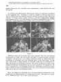
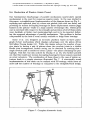
Here, the design of a shoulder joint of unconventional architecture is described and the characteristics of a prototype discussed. This paper is a sequel
to [7]. Please see Fig. 1 for a view of the prototype.
In Experimental Robotics 3, Yoshikaswa, T., Myiazaki, F (Eds.),
Lecture Notes in Control and Information Sciences 200. Springer Verlag. pp. 297--309.
299
2. D e s i g n
The major characteristic of a manipulator shoulder joint is that it works with
the worst possible m e c h a n i c a l advantage, and yet its bulk and weight must
be minimized, although this last requirement is obviously less critical than it
is for distal joints. In the applications of robots in hazardous environments,
this requirement is nevertheless crucial because a manipulator is typically n o t
a grounded structure, but instead, is supported by a gross positioning device:
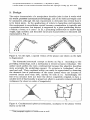
a vehicle, a boom, or a crane. 1 In [7], a promising architecture to achieve light
weight, high mobility and favorable structural characteristics is discussed and
represented in Fig. 2.
Figure 2. On the right, a spatial version of the planar case shown on the right
is diagrammed.
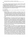
The kinematic/structural concept is shown on Fig 3. According to the
prevailing terminology, such a mechanism is termed actuator redundant. The
author much prefers the term combinatorial because this adjective describes
more accurately the underlying concept. No actuator is 'redundant': all are
used and well. Their combined utility can easily be appreciated by observing
the dramatic loss of performance of the entire system when one actuator in
removed (much more than 25%, anyway we look at it). Interestingly, the
loss of an actuator does not leave the device completely crippled, in fact, a
notable level of functionality is preserved, albeit in a greatly reduced controlled
workspace (by about an order of magnitude).
Figure 3. Combinatorial spherical mechanism, analogous to the planar version
shown on the left
1This paragraph applies to human arms as well!
In Experimental Robotics 3, Yoshikaswa, T., Myiazaki, F (Eds.),
Lecture Notes in Control and Information Sciences 200. Springer Verlag. pp. 297--309.
300
2.1. Kinematic Concept
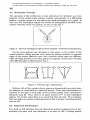
The operation of this architecture is best understood by viewing it as a combination of four piston-crank systems working cooperatively in a differential
fashion, a spatial version of a two piston-one-crank mechanism, so to speak. In
this case, four topological regions can readily be distinguished, labelled by the
relative velocities of the two pistons, as seen on the Fig. 4.
Figure 4. The four topological regions of the simplest combinatorial mechanism.
For the more general case discussed in this paper, in the vicinity of the
central position, tilting motions occur when the pistons attached to opposite
edges of the square platform move with velocities whose signs are different,
while swiveling motions occur when pistons in opposite corners have velocities
with differing signs as illustrated in Fig. 5.
Figure 5. Velocity sign combinations.
Motions with all four equals velocity signs are kinematically prevented since
the platform is constrained to a spherical motion. These sign relationships are
captured by the signs of each entry in the Jacobian matrix of the mechanism's
kinematic map [8]. Thus, there is an upper bound of 212 of such topological
regions, but at this point there is no proof that they all exist. The transition
from one region to another is illustrated in the Fig. 6 during a swiveling motion
with no tilt.
2.2. Expected Performance
The study in [13] indicates that the theoretical optimal workspace free of singularities (all parts with zero thickness) is as large as 180° of tilting motion
In Experimental Robotics 3, Yoshikaswa, T., Myiazaki, F (Eds.),
Lecture Notes in Control and Information Sciences 200. Springer Verlag. pp. 297--309.
301
Figure 6. The platform swivels, two of the actuators' contributions to the
swiveling torque vanish while the other two's reach their maximum mechanical
advantage. A similar situation occurs for all the topological region transitions,
which explains the exceptional extent of the working region having high kinematic conditioning.
in both directions and 270 ° of swivel. Of course, this ideal performance must
be compromised for kinematic performance, structural properties, and space
to lodge bearings and actuators. W h a t has actually been achieved in the first
prototype is about 90 ° of tilting motion in both directions and 180 ° of swivel.
These figures are expected to be improved substantially in a future prototype.
T h e large workspace increase makes it possible to take full advantage of
the efficiency of parallel linkages as discussed in [9]. In effect, during most
motions of the joint all four actuators move, each contributing mechanical
power combined at the output link, because the actuator efforts sum and they
all move. The worst case occurs when two actuator velocities vanish, in which
case these actuators may only play a structural role. The best case occurs when
all four actuators move at the same velocity and exert the same effort.
In a competing serial arrangement, during movements where the joint is
kinematically well conditioned, only one actuator is producing mechanical power,
the others have low velocity and uselessly dissipate power to support their
neighbors, while the strength of the joint is limited by the weakest link. The
worst case occurs when the joint is near a singularity when some actuators move
at high speed exerting little effort, thus operating at low efficiency. Moreover,
in a serial arrangement the stiffness of the group is limited by the stiffness of
the weakest joint, whereas in the parallel case, their stiffness add.
As a result of the previous observations, excellent strength-to-weight ratio
and power-to-weight ratio are expected over a large workspace, made possible
by 'actuator redundancy'. The moving mass lumped at the output link is about
1 Kg at a lever arm of about 0.1 m, resulting in a moment of inertia of the
order 0.01 Kg.m 2. Considering t h a t the joint can produce a torque of 200 N.m
(with a low supply pressure of 3.3 MPao500 psi), flat within a bandwidth of at
least 100 Hz in isometric conditions around any of the three rotation axes~ its
performance can be quite remarkable. We are now in position to examine the
tradeoffs which were confronted to come up with a practical shoulder joint.
In Experimental Robotics 3, Yoshikaswa, T., Myiazaki, F (Eds.),
Lecture Notes in Control and Information Sciences 200. Springer Verlag. pp. 297--309.
302
2.3. Dimensioning
The investigations carried out to determine the range of parameters for a useful device resulted in several important observations reported in [13]. It was
found that conventional kinematic indices could in fact be quite misleading
in the search for a useful device if physical limitations were not taken into
account. Another important and related observation is the low sensitivity
of kinematic performance as a function of the design parameters, except at
s c a t t e r e d trouble spots. This was typified by the need to use log scales to
concisely summarize results. The upshot of the study is that kinematic design
for manipulators is better described as the avoidance of debilitating conditions
rather than targeting for sharp optima.
When J is the manipulator Jacobian, al,O'2,0"3 are its singular values,
k(J) -= alia3 is its condition number, three such indices were used in a hierarchical design method: global conditioning, actuator forces minimization,
and global gradient index. The second and third indices were introduced for
the first time:
f w Dtdw
Dg= fwdw
fwd
Gng = maxGnz
~,y
-
=
f w 1/k(J)dw
fwdw
Yw
maxllvntll
w
(1)
(2)
(3)
Referring to Fig. 3, it was found that the general case mechanism could be
made isotropic with a conditioning ideally flat for the values Ib = lp = 21d
(units are irrelevant: since it is a spherical mechanism, its properties are scale
invariant). In practice, for a shoulder mechanism, there is no reason why it
should be isotropic. Actually, it should have greater strength around the axis
working against gravity. The scale of the device is directly related to the stroke
of the actuators.
Due to the vast number of actual design parameters, a trial and error was
used to precisely determine the final dimensions of the device: first with the construction of a series of physical models of increasing fidelity and then checking
with the indices listed above that performance was indeed acceptable. Most
importantly, the decision tree was rooted in the actuator choice (see section
2.5). At the first level, many decisions were dictated by the necessity of pistontype actuators to have their shortest length exceed their maximal stroke. From
this observation, attaching the cylinders by their ends would necessarily lead
to poorly conditioned mechanisms. To overcome this difficulty, the cylinders
must protrude and be placed in cradles, thus ruling out use the square platform (Fig. 3) as the output link. The final dimensioning decisions where made
by considering avoidance of self collisions and structural strength (see section
2.6). The entire decision process resembled searching for a Nash equilibrium
(conflicting objectives) in game theoretic optimization problem [20].
In Experimental Robotics 3, Yoshikaswa, T., Myiazaki, F (Eds.),
Lecture Notes in Control and Information Sciences 200. Springer Verlag. pp. 297--309.
303
2.4. R e d u c t i o n of P a s s i v e J o i n t s C o u n t
One fundamental disadvantage of parallel mechanisms (particularly spatial
mechanisms) is the need for numerous passive joints. In the case studied in
this paper, a straightforward implementation of the diagram shown on Fig. 3-replacing each spherical joint by a three axis gimbal (each with two forks) and
providing for torsion decoupling bearings for linear displacement sensors piggy
backed on the pistons--leads to a large number of bearings (45). Unless great
care is exercised with respect to the strength and precision of all of these joints,
wear, backlash, or failure (not mentioning high cost) is to be expected, defeating the supposed advantages of parallel mechanisms. This problem is further
compounded by the lack of room usually available to lodge these bearings.
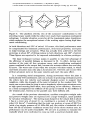
Inoue et al. [11] designed an iso-static platform based on three pantograph (5-bar) mechanisms which displays advantages over the piston driven
McCallion-Truong design [14]. While this design reduces the number of passive joints by having a pair of pistons share two revolute joints in a double
Hooke joint arrangement, further saving can be obtained by noticing that a
single revolute joint is needed to orient a plane--the plane containing the pantograph. This fact was also noticed by Dunlop et al. [6], who further pointed
out that this would save torsion decoupling bearings for linear sensors mounted
on screw actuators. The combination of these ideas to the case of piston actuators leads to a simple structure illustrated Fig. 7. A structurally sound
implementation of this chain can be realized with 25 bearings, which saves almost half the number of bearings as compared to the straightforward design.
(b)
Figure 7. Complete kinematic chain.
In Experimental Robotics 3, Yoshikaswa, T., Myiazaki, F (Eds.),
Lecture Notes in Control and Information Sciences 200. Springer Verlag. pp. 297--309.
304
The bearings, although supporting large loads, could be made very small
and yet have little backlash thanks to a technique developed at the Center for
Engineering Design at the University of Utah.
Finally, yet another benefit of actuator redundancy contributes to ensure
the elimination of the residual backlash. In any given orientation of the mechanism, internal stresses can be actively created, independently from the external
load, thus bias-loading all the mechanism's bearings.
2.5. A c t u a t o r s
It is suggested here that the actuator analysis problem in robotics might be
split into four items:
E n e r g y Storage. Under this heading, one considers the form under
which the energy needed to actuate the robotic device is stored. In a
manufacturing application, this question of is small importance since it
can reasonably be assumed that an unlimited supply of energy is available. In other applications of robotics, this item can play a major role,
for example for planetary explorations vehicles or untethered submarine
rovers, in which case a capacious energy storage must be part of the robot
itself.
E n e r g y T r a n s p o r t . One considers the method by which energy is transported from storage to a final stage, where it must be available in mechanical form. In most cases, this function is performed in multiple steps.
For example in an electric industrial robot, energy is transported in electrical form, converted into mechanical form in the manipulator's motors
and then, most often, once again mechanically transported to the joints
via gears, shafts, belts, chains, cables, tendons, hydraulic or pneumatic
conduits, or other mechanical energy transmission techniques. A 'direct
drive' robot is characterized by the absence of mechanical transmission
of energy, except by the structure of the manipulator itself (hence most
hydraulic robots are direct drive).
E n e r g y T h r o t t l i n g . One considers here the method whereby energy
is throttled to ensure control over the robot. Energy throttling is hard
to achieve mechanically (clutches do that inefficiently). Among a large
number of possibilities, electric energy throttling is usually the method
of choice, even in a multi-step process as for electromagnetic servovalves.
Regardless of the type of energy being throttled, there are three basic
methods. In the first method, constant power is delivered by the supply,
and the throttling mechanism arranges for a variable amount of the effort
to be diverted to the load, usually by creating an effort imbalance. An
electric version of this principle leads to 'class A' amplifiers, a hydraulic
version of it leads to the jet pipe hydraulic valve. In the second method,
the power delivered by the supply varies with that delivered to the load
('class B') limiting the loss in the throttling mechanisn~L But in this
case the throttling mechanism must have large bandwidth because the
In Experimental Robotics 3, Yoshikaswa, T., Myiazaki, F (Eds.),
Lecture Notes in Control and Information Sciences 200. Springer Verlag. pp. 297--309.
305
power must be switched from throttling to quiescence, and vice versa, at
each reversal of the direction of the energy flow. In the third method,
in some sense a limiting case of the previous case, power is switched,
and switching timing is used to throttle power. Then it must have even
higher bandwidth to approximate ideal switching. This topic is not often
studied in robotics, although it is quite a thorny problem more often than
generally assumed (example: variable reluctance electric actuators).
E n e r g y C o n v e r s i o n . Under this last item, one must examine which
principle is applied to convert a transportable form of energy into mechanical energy. T h e reader is referred to [10] for a recent survey.
Most actuator systems accomplish transport, throttling and conversion in
multiple steps. Hydraulic techniques have been selected for use in this shoulder
joint prototype enabling direct application in areas in which new manipulator
designs are in need, in particular telerobotics. In this area, often, the levels
of performance are attainable only with hydraulic actuation. Also the recently
available force-controlled ASI integrated hydraulic actuators offered a path toward rapid creation of a high performing prototype. In a number of telerobotic
applications, there is need for human-like performance in terms of bulk, precision, strength, reach and dexterity. Again, only hydraulic actuators can be
made compact enough to even consider approaching the level human performance. Thus, with this in mind, the four items listed above can be discussed. 2
Because of the large amount of power required by hydraulic actuators, the
energy storage can only be utility-supplied, or be stored chemically in conjunction with a first conversion stage provided by a turbine or an internal
combustion engine. This is the method used in many 'pre-robotic' devices such
as cranes, excavators, forestry or mining equipment. In submarine applications, high levels of power may be made available through umbilical cables.
With hydraulics, the transport function is accomplished with hydraulic lines
which must be run from the source of pressure to the actuators. Lines have
their own dynamical properties which are actually best described as distributed
parameters systems. For this reason, their dynamics are not simple and they
can account for significant losses in energy and performance. Hence, compact
high-bandwidth valves that can be co-located with the actuators themselves
are quite advantageous from a control view point.
With this technique, excellent performance using locM compensation can
be obtained, even with long and ill-modelled lines. The valve itself is only a
part of the energy throttling mechanism since it is driven by an electromagnetic
motor, itself driven by an electronic amplifier. In the case of the ASI actuators
it was found that the electromagnetic energy conversion mechanism was in
fact a limiting factor in the performance of the complete actuator. The last
stage of the energy throttling mechanism is based on forcing the fluid through
orifices whose areas can be controlled and the last stage of energy conversion
is accomplished simply by letting the fluid pressure act differentially on the
sit a worthwhile to reflect on Nature's solution to these four problems.
In Experimental Robotics 3, Yoshikaswa, T., Myiazaki, F (Eds.),
Lecture Notes in Control and Information Sciences 200. Springer Verlag. pp. 297--309.
306
sides of pistons or vanes. Details on the properties and compensation control
of these actuators can be found in [1].
2.6. S t r u c t u r a l Design a n d Collision A v o i d a n c e
The structural design was carried out while attempting to take full advantage of
the opportunities offered by parallel linkage mechanisms. For example, pistons,
as opposed to rotary vane actuators, can be used as structural members and
thus economically contribute to strength. Piston actuators have in general
numerous structural advantages over rotary actuator while being simpler to
manufacture and maintain, and they have greater efficiency.
The principal structural parts are listed by order of decreasing design difficulty: (a) Central stem (1 unit); (b) Double Hooke joints (2 identical units);
(c) Actuator cradles (4 identical units); (d) Double actuator forks (2 identical
units); (e) Output flange (1 unit); (f) Ground link (I unit); As it can be seen,
the number of parts is quite reasonable are they can be made to have rather
simple shapes. The loads types and magnitudes in each bearing was examined,
and correspondingly sized.
In the current state of prototype, no systematic structural optimization was
carried out, using finite element methods for example, but that could be done
in the future. It is encouraging to see that the first sizing estimates used in this
first prototype already produced quite a light and compact system. Certain
deficiencies were noticed and will have to be corrected in future prototypes.
The main culprit in the reduction of the practical workspace is the possibility of self collisions well within the singularity-free work region. This topic
is not studied in any systematic fashion because of the great difficulty in its
formalization. General guidelines have been followed to alleviate this problem.
Ideally all parts should be as small as possible, but of course, this approach
has its limits.
Except for the output flange which is made of aluminum, the material selected for the construction of most of the structure is stainless steel to optimize
the strength to size ratio of its parts.
3. E x p e r i m e n t a l
Results
The shoulder joint was tested in the laboratory using a L-shaped member
designed to approximate the construction of a complete arm. It is made of two
steel tubes welded at a right angle with lengths 0.3 m each. It is bolted to
the output flange shoulder such that the axis of first tube coincides with its
axis of symmetry. This member is quite rigid and has a mass of 1.6 Kg. An
additional load mass of 1.4 Kg is affixed to the end of the second tube. The
moments of inertia of this composite load about the joint center of rotation are
approximately 0.62 Kg.m2, 0.48 Kg.m2, and 0.15 Kg.m2.
In an attempt to decouple the basic performance of the design from that of
the various control algorithms currently under investigation, the simplest feedback controller is used. It is a proportional position feedback controller about
each actuator, augmented by a lag term for improved steady-state accuracy.
In Experimental Robotics 3, Yoshikaswa, T., Myiazaki, F (Eds.),
Lecture Notes in Control and Information Sciences 200. Springer Verlag. pp. 297--309.
307
The controller is implemented digitally at a servo rate of 1 kHz. We have also
implemented a force regulator of similar design.
We executed a small step motion about the axis of highest inertia, in the
middle of the joint range. In this condition, the shoulder is capable of producing
accelerations of 130 m/s 2 at the tip where the wrist joint is to be located, and
a maximum tip velocity of 0.45 m/s was observed. The maximum static force
produced at the wrist varies from a worst case of 200 N to a best case of 400
N, according to direction of the exerted force, at the center of the shoulder
joint range. The force control bandwidth is observed to be about about 100Hz.
Position resolution could not be measured with the available equipment.
The basic low velocity and force resolution performance is not a function
of the design since it can be qualified of being "direct drive" (there are no
motion transmission elements other than simple linkages interposed between
the actuators and the load). Low velocity performance and force resolution
depend completely on the actuators, sensors and local feedback control. To
date, experiments in this area have been limited solely by the resolution of the
12 bits analog to digital converters used for digital control.
4. C o n c l u s i o n
A manipulator shoulder joint design based on a combinatorial mechanism which
addresses several issues of concern in telerobotics was described. A large
workspace was achieved despite the use of parallel linkages, thereby offering
an opportunity to take advantage of their possibilities in terms of structural
strength and precision. The joint is efficient because any motion in any direction combines the contribution of at least 3 and almost everywhere of 4
actuators, where a serial joint could use only one actuator. They are also advantages from a control view point, in terms of impedance modulation and
control robustness, when compared to a serial arrangement as described in [2].
As a result of the preceding items, a dramatic improvement in power-toweight ratio has been achieved while construction was kept simple and the
number of parts minimized, while low pressure hydraulics led to a significant
torque output. Moreover, four identical piston type actuators, which are the
simplest to manufacture and to maintain, were used exclusively.
This design provides a path toward the development of a highly reliable
system since it has built-in redundancy. There is natural provision for self calibration: sensors, kinematics, and dynamics. Initial success in this direction has
been achieved [16]. Self-testing is natural extension of self calibration: Work is
under way to investigate the automatic diagnostic of partial structural, actuator, and sensor failures as well as backlash. Finally, there is built-in provision
for degraded modes of operation with missing sensors, missing actuators and
minor structural failures. Moreover backlash can be actively compensated.
At the time of this writing, an elbow joint using two actuators identical to
those used in the shoulder is under construction. A compact wrist mechanism
with four smaller actuators is also in the design stage. All these joints are based
on design principles described in this paper and will result in a manipulator
In Experimental Robotics 3, Yoshikaswa, T., Myiazaki, F (Eds.),
Lecture Notes in Control and Information Sciences 200. Springer Verlag. pp. 297--309.
308
arm with high dexterity, high strength-to-weight ratio, powered by 6 replicated
piston actuators and 4 smaller ones, also identical.
5. Acknowledgments
I am indebted to many people who contributed to this project in various
ways: in particular Dr. Fraser Smith and David Barret from Sarcos Research Corp. for their first class engineering design and prototype realization,
Prof. Stephen C. Jacobsen for his encouragements and valuable comments,
Benoit Boulet and Ronald Kurtz, for their excellent work, Prof. Laeeque
Daneshmend for his contribution to modeling and control of actuator systems,
Chafye Nemri and Duncan Baird for their engineering support. Finally, I would
like to thank Profs. I. W. Hunter and J. M. Hollerbach for their support within
the project "High-Performance Manipulators" (C3) funded by IRIS, the Instit u t e for Robotics and Intelligent Systems part of Canada's National Centers of
Excellence program (NCE). Additional funding was provided by a team grant
from FCAR, le Fond pour les Chercheurs et l'Aide ~ la Recherche, Qudbec,
and an operating grant from NSERC, the National Science and Engineering
Council of Canada.
References
[1] Boulet, B., Daneshmend, L. K., Hayward, V., Nemri, C. 1993. System Identification and Modelling of a High Performance Hydraulic Actuator. Experimental
Robotics 2, Chatila, R., Hirzinger, G. (Eds.), Lecture Notes in Control and
Information Sciences, Springer Verlag.
[2] Boulet, B., Hayward, V. 1993. Robust control of a robot joint with hydraulic
actuator redundancy. Part I: Theory application and controller design. Part
II: Practical variations and experimentation. TR-CIM-93-6 and TR-CIM-93-7.
Technical Report, McGill Center for Intelligent Machines. McGill University,
Montreal Canada.
[3] Burdick, J. W. and Chirikjan. Hyper-redundant robots: kinematics and experiments, in Preprints of 6th International Symposium on Robotics Research, Oct.
2-5, Hidden Valley, PA.
[4] Charentus, S., Renaud, M. 1990. Modelling and Control of a Modular, Redundant Robot Manipulator. in Experimental Robotics 1, Hayward, V., Khatib, O.
(Eds.), Lecture Notes in Control and Information Sciences 139. Springer Verlag,
pp. 508-527.
[5] Dietrich, J. Hirzinger, G., Gombert, B., Schott, J. 1990. On a unified concept for
a new generation of light-weight robots, in Experimental Robotics 1, Hayward,
V., Khatib, O. (Eds.), Lecture Notes in Control and Information Sciences 139.
Springer Verlag, pp. 244-286.
[6] Dunlop, G. R., Johnson, G. R., Afzulpurkar. 1991. Joint design for extended
range Stewart platform applications. Proc. Eight World Congress on the Theory
o] Machines and Mechanisms. Prague, Czechoslovakia. Vol. 2. pp. 449-451.
[7] Hayward V. 1993. Borrowing some design ideas from biological manipulators
to design an artificial one. In Robots and Biological Systems, NATO Series, P.
Dario, P. Aebisher, and G. Sandini, (Eds.), Springer Verlag. pp. 139-151.
In Experimental Robotics 3, Yoshikaswa, T., Myiazaki, F (Eds.),
Lecture Notes in Control and Information Sciences 200. Springer Verlag. pp. 297--309.
309
[8] Hayward, V. Kurtz, R. 1991. Modeling of a parallel wrist mechanism with actuator redundancy. In Advances in Robot Kinematics. Stifter, S., Lenarcic (eds.).
Springer-Verlag. pp. 444-456.
[9] Hirose, S., and Sato, M. 1989. Coupled drive of the multi-DOF robot, in Proc.
IEEE Int. Conf. on Robotics and Automation, pp. 1610-1616.
[10] Hollerbach, J. M., Hunter, I. W., Ballantyne, J. 1991. A comparative analysis of
actuator technologies for robotics. In Robotics Review 2, Khatib, O., Craig, J.,
Lozano-Perez, T. (eds.), MIT Press.
[11] Inoue, H., Tsukasa, Y., Fukuizumi, T. 1986. Parallel manipulator. In The Third
International Symposium on Robotics Research. Faugeras, O. E., Giralt, G.
(Eds.). MIT Press. pp. 321-327.
[12] Jacobsen, S. C., Smith, F. M., Backman, D. K., and Iversen, E. K. 1991. High
performance, high dexterity, force reflective teleoperator II. in Proc. ANS Topical
Meeting on Robotics and Remote Systems.
[13] Kurtz, R., Hayward, V. 1992. Multi-goal optimization of a parallel mechanism
with actuator redundancy. IEEE Transactions on Robotics and Automation.
Vol. 8, No. 5. pp 644-651.
[14] McCallion, H., Truong, P. D. 1979. The analysis of a six degree of freedom work
station for mechanized assembly. Proc. 5th World Congress on the Theory of
Machines and Mechanisms, pp 611-616.
[15] Morecki, A., Malczyk, G. 1987. Mathematical Model of a flexible manipulator of
the elephant's-trunk-type, in Proe. Sixth CISM-IFToMM Symposium on Theory
and Practice of Robot and Manipulators, Morecki, A., Bianchi, G., Kedzior, A.
(Eds.), Hermes, Paris.
[16] Navhi, A., Hollerbach, J. M., Hayward, V. Calibration of a parallel robot using
multiple kinematic loops. Submitted to 1994 IEEE Int. Conf. on Robotics and
Automation.
[17] Pierrot, F., Dauchez, P., Fournier, A. 1991. Hexa a fast six-dof fully parallel
robot. Proc. 5th Int. Conf. on Advanced Robotics, Pisa, Italy. IEEE Press.
[18] Rosheim, M. E., 1989. Robot wrist actuators, John Wiley & Sons.
[19] Regan, B. 1991. ATLAS-8F Advanced Bilateral Manipulator System. In Proc.
of ROV-91 Conference, Marine Technology Society. Washington DC.
[20] Vincent, T. L. 1983. Game theory as a design tool. J. of Mechanisms, Transmissions, and Automation in Design, Trans. o/ ASME, Vot. 105, No. 1, pp.
165-170.
[21] Yoshinada, Hiroshi, Yamazaki, T., Suwa, T., Naruse, T. 1992. Design and control
of a manipulator system driven by seawater hydraulic actuator. Proc. Second
Int. Symposium on Measurement and Control in Robotics (ISMCR), Tsukuba
Science City, Japan, pp. 359-364.