1
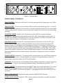
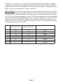
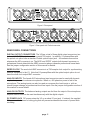
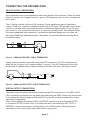
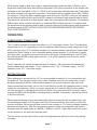
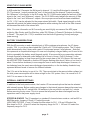
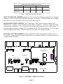
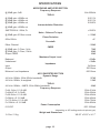
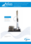
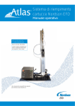
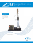
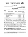
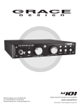
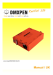
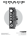
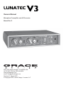
Owners Manual
Microphone Preamplifier and A/D Converter
Manual Rev E
2434 30th Street, Boulder, CO 80304 USA
tel 303.443.7454 fax 303.444.4634
www.gracedesign.com
email: [email protected]
Revision D March 2005
© Copyright 2005, Grace Design / Lunatec LLC
Thank you for purchasing the lunatec V3 portable microphone preamplifier and A/D converter.
It is designed and built to be extremely reliable, flexible and easy to use. This owner’s manual
provides comprehensive setup and operational instructions, including directions for changing
various preamplifier settings via the internal jumpers. Please take the time to familiarize yourself
with these instructions, which will help you help you get the most from your lunatec V3.
Grace Design has been building professional audio products for the recording industry for over ten
years. During this time the circuit technology embedded in the lunatec V3 has evolved through
a process of extensive listening, testing and refinement. Regardless of what audio sources you
plan to record, the lunatec V3 will faithfully serve as an invisible link between your microphone
and recording device. We hope it helps you achieve a new level of excellence in your audio
recordings.
FEATURES OF THE LUNATEC V3 PREAMPLIFIER
•
High fidelity stereo preamplifier circuit with balanced inputs and outputs
•
11 position gain control with 5dB steps
•
10-70dB gain range
•
10dB continuously variable trim control
•
48 Volt phantom power for microphones
•
8 segment dot mode level meters
•
Two position High Pass Filter with 6 or 12dB/octave slope
•
Mid-Side recording matrix
•
24-bit A/D converter with 44.1, 48, 88.2, 96, 176.4 and 192kHz sample rates
•
ANSR™ Analog Noise Shaped word length Reduction for 16-bit output
•
Single and dual wire operation for 88.2-192kHz sample rates
•
Professional and consumer digital signal formats
•
Word clock output
•
Input attenuator for line level input A/D operation
page 2
Figure 1. V3 Front Panel
FRONT PANEL CONTROLS
GAIN CONTROL Each gain control has 11 positions and adjusts the voltage gain from 10dB to
60dB in 5dB steps.
TRIM CONTROL The trim control provides 10dB of continuously variable gain trim. In the fully
counter-clockwise position the trim is at unity. In the fully clockwise position the trim control adds
10dB of additional gain. The trim control can be used to adjust the record level smoothly during
recording.
PHANTOM POWER (labeled +48) This switch provides 48 Volts to power condenser
microphones. The phantom power switch connects the +48V power supply to pins 2 and 3 on
the XLR input connector. Alternatively, the V3 can be configured to provide 12V Parallel power.
Please contact the factory for information on this option.
HIGH PASS FILTER (labeled HPF) Sometimes referred to as a bass roll-off, the HPF uses
a three position toggle switch to select two different low cut corner frequencies and an OFF
position. Position 1 is the higher cutoff frequency and Position 2 is the lower cutoff frequency.
Internal jumpers allow for selection of either 6dB/octave (passive) or 12dB/octave (active) slope.
Also, internal jumpers select the cutoff frequencies at 50Hz/100Hz or 75Hz/125Hz. The 12dB/
octave filter employs a transitional Thompson-Butterworth response for the best combination of
pass-band flatness and time domain response. See jumper confuguration section for detailed
information.
POWER SWITCH (labeled 0-I) The power switch connects power from the DC input connector
to the preamplifier circuitry. If the preamplifier is connected to a charged battery or other DC
power supply, one of the sample rate LED’s will illuminate.
LOW BATT For the 6 Volt V3, the low battery indicator flashes if the battery voltage drops below
5.75V. For the 12 Volt V3, the low battery indicator flashes if the battery drops below 11.5V.
ANSR™ SWITCH This switch activates the ANSR™ dither circuit which allows the V3 to output
16-bit data on its digital outputs. The amber ANSR™ LED will illuminate when this circuit is
active. Use the ANSR™ circuit when recording to 16-bit digital devices such as DAT and CD-R
recorders.
PEAK CLEAR SWITCH Pushing this switch clears the 0dBFS/OVER indicators.
SAMPLE RATE SELECT (labeled Fs SEL) Sample rates are selected by pushing and holding
page 3
this switch for 1/2 second. The 1/2 second delay before the sample rate changes is designed
to help prevent accidental rate changes while recording. When the “OFF” position is selected,
the AD converter module is powered down to reduce power consumption. The sample rate and
ANSR™ state are saved when the V3 power is turned off.
LEVEL METERS The LED level meters operate in dot mode rather than bar mode. This saves
a considerable amount of battery power while still providing useful peak signal level information.
The meter scale is calibrated in dBFS to indicate the amount of headroom at the A/D converter.
The “0” LEDS are dual purpose indicators: the “0” LED will illuminate when the signal presented
at the A/D converter reaches 0dBFS but will “latch” on when an “OVER” has occurred. The LED
will stay illuminated until the PEAK CLEAR button is pressed. 0dBFS also corresponds to an
analog output level of +25dBu on the balanced output connectors. The following table indicates
the analog output levels for each LED.
dBFS
ANALOG OUT
BALANCED (dBu)
ANALOG OUT
UNBALANCED (dBu)
LED COLOR
0
-3
-6
-9
-12
-15
-21
-27
+25
+22
+19
+16
+13
+10
+4
-2
+19
+16
+13
+10
+7
+4
-2
-8
RED
AMBER
AMBER
AMBER
GREEN
GREEN
GREEN
GREEN
page 4
Figure 2. Rear panel
Figure 3. Rear panel with Toslink connector
REAR PANEL CONNECTIONS
DIGITAL OUTPUT CONNECTORS The V3 has a total of three digital output connectors: two
balanced XLR 110Ω outputs and one coaxial 75Ω output. In addition, V3 preamplifiers with
the optical out option have a standard Toslink optical output jack. All connectors are active
whenever the A/D converter is on. The AES1 and S/PDIF outputs both transmit consumer or
professional format data while the AES2 connector always transmits professional format data.
See the jumper configuration section of this manual for details.
WORD CLOCK The word clock BNC connector is a 75Ω sample clock output for synchronizing
external equipment to the V3. Note that V3 preamplifiers with the optical output option do not
have the word clock output BNC connector.
ANALOG INPUTS The female XLR microphone input connectors can be used with dynamic
or phantom powered condenser microphones. When on, 48V phantom power is fed to the
microphone. The analog inputs can also be used as consumer line level inputs or, with an
internal jumper change, as professional level line inputs. See the jumper configuration section of
this manual for more details.
ANALOG OUTPUTS The balanced analog outputs are fed from the output of the microphone
amplifier section and can be used simultaneously with the digital outputs.
DC POWER JACK DC power enters the V3 on a robust 2.1mm jack. If ordered, the supplied
DC power cable features a locking plug that will prevent accidental disconnect of power while
recording.
page 5
CONNECTING THE PREAMPLIFIER
ANALOG AUDIO CONNECTIONS
Input connections from a microphone are made using female XLR connectors. These are wired
with pin 2 positive, pin 3 negative and pin 1 ground. 48V phantom power, if used, is supplied on
pins 2 and 3.
The V3 can be used as a line level A/D converter. If input signal levels are not expected to
exceed +15dBu (i.e. consumer unbalanced signal from a CD player, DAT recorder, home stereo
receiver or cassette deck) then simply connect an unbalanced signal into the V3, set the input
gain control to 10 and adjust the trim control for optimum recording levels. See the figure below
for proper unbalanced input termination. If professional balanced signals are to be used, set
the internal 20dB input attenuator jumpers. Remember to reset these before recording with a
microphone again.
Figure 3. UNBALANCED INPUT CABLE TERMINATION
Analog output connections are made using male XLR connectors. The XLR connectors are
wired with pin 2 positive, pin 3 negative and pin 1 ground. If the XLR outputs are to be used
unbalanced, a modified cable is required and pin 3 should be left open. See figure 2 below.
Figure 4. UNBALANCED OUTPUT CABLE TERMINATION
DIGITAL OUTPUT CONNECTIONS
The digital output connectors are all active whenever the A/D converter is on. The AES1 and S/
PDIF connectors are derived from the same transmitter while the AES2 connector is derived from
it own transmitter. Internal jumpers ADJ6 and ADJ7 on the AD converter module set the output
data format configuration.
ADJ7 selects whether the data from AES1 and S/PDIF connectors is in Professional (AES3)
or Consumer (S/PDIF) format. If the V3 is being used with a consumer type DAT, CD-R, or
MINIDISK, it may be necessary to set the jumper in the CONS position. Most professional
equipment is not too picky about which data format is being used.
page 6
ADJ6 selects single or dual wire mode for transmitting high sample rate data. If ADJ6 is set in
single wire mode then stereo data will be transmitted on all output connectors at the sample rate
indicated on the front panel of the V3. If ADJ6 is set for dual wire operation then the V3 will divide
the stereo channels into two mono signals at ½ the sample rate for sample rates of 88.2-192kHz.
For instance, if using the 96kHz sample rate in dual wire mode, the AES1 connector will transmit
the left channel data at 48kHz and the AES2 connector will transmit right channel data at 48kHz.
This allows for transmission of high sample rates over lower sample rate hardware. For example,
96kHz stereo audio could be recorded to a 4 channel 48kHz digital recorder. It is required that
the equipment at the receiving end be able to process the mono signals properly and reconstruct
the stereo signal. NOTE THAT ADJ7 MUST BE IN PROFESSIONAL MODE FOR PROPER
DUAL WIRE OPERATION.
OPERATION
POWER SUPPLY CONNECTIONS
The V3 can be ordered to operate from either 6 or 12 Volt power sources. The V3 current draw
ranges from .6A to .1A, depending on the microphones used (Phantom power usage) and if the
A/D converter is on or off. For battery operation it is recommended to use the input power cable
supplied by Grace Design or from a reputable battery system supplier. If you choose to supply
your own cable, we would recommend the wire be 20 gauge or larger and the 2.1mm DC plug
be a Switchcraft S760K locking type connector. +V is on the center pin and Ground is on the
outside conductor.
For AC operation the V3 can be used with and AC adaptor. We recommend purchasing the
proper adapter from your dealer. For 6V operation use a 7.5V, 1.0A power supply. For 12V
operation use a 12V, 1.0A power supply.
SETTING THE GAIN
When preparing to record with the V3 it is recommended to make all of your connections with
the power off. Turn the gain control fully counter-clockwise, turn the trim control fully counterclockwise and check that the +48V phantom power is off on both channels. After input and
output connections are made, turn on the V3 and then turn on the 48V phantom power (if using
condenser microphones). (Note: it is always good practice to have the 48V phantom power
off when plugging or unplugging microphones.) When using the internal A/D converter, simply
increase the gain until the optimum recording level is reached. If necessary, use the trim control
to fine tune the level.
When using the analog outputs and sending the signal to a recorder with a variable input, use
the following procedure: turn the gain control fully counter-clockwise, turn the trim control fully
counter-clockwise. Set the record level control on the recorder to 12 o’clock or midway between
minimum and maximum. With the sound source present, adjust the preamplifier gain control
clockwise until the signal peaks at –9dBFS (+16dBu) on the V3. Adjust the record level control
on the recorder for the optimum recording level.
The trim control can be used for fine output level adjustment as well as for level riding during
recording.
page 7
USING THE V3 IN M-S MODE
In M-S mode the V3 accepts the Mid signal in channel 1 (L) and the Side signal in channel 2
(R). The channel 1 output provides the “sum” of the inputs and the channel 2 output provides
the “difference” of the inputs. In the M-S mode, the CH 1 GAIN control adjust the amount of Mid
signal in the “sum” and “difference” outputs. The CH 2 GAIN control adjusts the amount of Side
signal in the “sum” and “difference” outputs. Once a proper record level has been established
for CH 1, CH 2 can be adjusted for the proper stereo field width. Equal signal strength on both
channels will provide the widest stereo perspective while reducing the level of the Side channel
will decrease the width of the stereo field.
Note: For more information on M-S recording we would highly recommend the AES paper
written by Wes Dooley and Don Streicher called “M-S Stereo: A Powerful Technique for Working
in Stereo”. This paper (No. 1792) is available from the Audio Engineering Society web page
(www.aes.org)
BATTERY CONSIDERATIONS
With the AD converter on and a standard pair of 48V condenser microphones, the V3 draws
roughly .75A. In our lab we have tested the V3 with a 6V 7.2A/h battery system. The V3 shuts
down automatically after 8 hours with a pair of Countryman Isomax II microphones. Note that
this represents a complete discharge of a new and completely charged battery and if used in this
fashion repeatedly the battery would degrade rapidly. 6 hours would be a conservative estimate.
A simple formula to determine useful battery life in hours is Hours= (Cx0.6)/A where C is the
capacity of the battery in Amp-Hours and A is the current draw of the V3 in Amps. We have set
the LOW BATTERY threshold so that the LED begins flashing after about 6 hours of run time (or
about 1 hours before shutdown) to encourage the user to avoid deep discharges. However, no
two batteries have the exact same discharge characteristics, so the low battery threshold may
represent different levels of reserve for different batteries.
The V3 is set at the factory to run at 6 or 12V. The current drain is the same at either voltage, but
the total power consumption will be twice as high for the 12V system. Also, it is normal for a 12
Volt V3 to run warm to the touch.
INTERNAL JUMPER SETTINGS
In addition to the front panel controls, the Lunatec V3 has several options that can be selected
with internal jumpers. Before making any changes to the internal jumpers always disconnect any
power source from the V3, switch both +48 switches to the on position and wait for 1 minute
before removing the top cover. This is to assure that all power has been discharged from the
capacitors used in the power supply circuit.
STEREO M-S MODE The V3 operates in a standard 2 channel stereo mode as well as M-S or
Mid-Side mode. Jumpers J12 and J17 select the mode.
HIGH PASS FILTERS J7 and J10 select the filter slope for CH1. J19 and J22 select the
filter slope for CH 2. J6 and J9 select the frequency range for CH 1. J20 and J21 select the
frequency range for CH 2.
page 8
HIGH PASS FILTER JUMPER SETTINGS
J6 J9 J20 J21
LOW
HIGH
HPF SWITCH
POSITION
1
2
1
2
CUTOFF
FREQUENCY
100Hz
50Hz
125Hz
75Hz
Table 1. HPF Filter Frequency Selection
INPUT ATTENUATOR JUMPERS Jumpers J3 and J4 select the 20dB input attenuator for channel 1.
Jumpers J14 and J15 select the 20dB input attenuator for channel 2. These should be set for –20dB
when the V3 is to be used with professional line level input signals.
MICROPHONE POWER JUMPERS The V3 can supply +48V Phantom power as well as 12V
Parallel power. Jumpers J1 and J5 select the mic power for channel 1. Jumpers J13 and J18 select
the mic power for channel 2. The V3 ships from the factory with the jumpers in the +48V setting. To
avoid possible microphone damage the V3 is shipped with the 12V setting disabled. The 12V setting
must be enabled at the factory. Please contact us if you need 12V microphone power.
DC SUPPLY VOLTAGE JUMPERS Jumpers J26 and J27 select the operation Voltage to be 6 or
12 Volts DC. These jumpers should be moved ONLY by a qualified technician. Consult the factory for
voltage change information.
J2
J1
12V{
48V{
J5
}-20dB
}0dB
}12V
}48V
}0dB
}-20dB
}-20dB
}0dB
J4
J14
J15
J13
}12V
}48V
J31
CABLE
J3
J28
J16
2W
AD MODULE
J18
ADJ6
1W
PRO
J20
S2
VR5
6V{
J26 VR7
J27
VR8
S4
FRONT PANEL
Figure 5. V3 INTERNAL JUMPER LOCATIONS
page 9
U19
12V{
12V{
ACTIVE{
ACTIVE{
STEREO{
S3
J22
PASSIVE{
VR6
MS{
PASSIVE{
PASSIVE{
J12
S1
J19
J17
U10
J21
ADJ7
6V{
MS{
VR2
J10
STEREO{
J7
ACTIVE{
J9
PASSIVE{
J6
HIGH
LOW
HIGH
LOW
LOW
HIGH
LOW
HIGH
HIGH
LOW
HIGH
LOW
R69
CONS
VR1
LOW
HIGH
LOW
HIGH
GRACE DESIGN
P300 REV A
ACTIVE{
12V{
48V{
}0dB
}-20dB
J11
U18
SPECIFICATIONS
@ 60dB gain -3dB
@ 20dB gain +20dBu out
@ 40dB gain +20dBu out
@ 60dB gain +20dBu out
@ 40dB gain +20dBu out
SMPTE/DIN 4:1 50Hz,7k
@ 60dB gain 50 Ohm source
50Hz-20kHz
Either Channel
@ 60dB gain, 3.5Vcm, 1kHz
@ 60dB gain, 3.5Vcm, 10kHz
Output CMRR
Balanced
Unbalanced
Input
Output
Minimum Load Impedance
MICROPHONE AMPLIFIER SECTION
Frequency Response
THD+N
Intermodulation Distortion
Noise - Referred To Input
Phase Deviation
Crosstalk
6Hz-250kHz
0.0011%
0.0011%
0.0046%
<.0045%
<-130dB
<8°
-109dB
CMRR
Maximum Output Level
Impedance
A/D CONVERTER SECTION
Dynamic Range
44.1kHz-192kHz, 22Hz-20kHz bandwidth
44.1kHz-192kHz, A-weighted
THD+N
44.1kHz-192kHz, -3dBFS, 22Hz-20kHz bandwidth
Frequency Response
Fs 44.1kHz +0.1/-0.4dB
Fs 48kHZ +0.1/-0.4dB
Fs 88.2kHz +0.1/-0.4dB
Fs 96kHz +0.1/-0.4dB
Fs 176.4kHz +0.1/-0.4dB
Fs 192kHz +0.1/-0.4dB
Power Consumption
6-12VDC
70dB
80dB
60dB
+25dBu
+19dBu
3k Ohms
300 Ohms
600 Ohms
107dB
110dB
-96dB
20Hz-21kHz
20Hz-22kHz
20Hz-42kHz
20Hz-45kHz
20Hz-75kHz
20Hz-82kHz
600-1000mA
(depending on A/D settings and microphone type)
Weight and Dimensions
2.6 lbs / 1.2kg
W8.25” x D5.5” x H1.7”
page 10
Lunatec V3 Owner’s manual addendum 1
Optional Toslink / Optical Output Option
toslink
6-12V
The Lunatec V3 Toslink / Optical option adds an additional digital output on the rear panel of
the V3 in place of the Word Clock out BNC connecter. The Toslink / Optical output is always
live and available in conjunction with all of the other outputs on the V3.
This optical output is derived from the same transmitter as the S/PDIF output, so its consumer/ professional status is also determined by the same internal jumper setting which is used
for the S/PDIF output. The Toslink output supports 44.1kHz, 48kHz, 88.2kHz, 96kHz.
Connections are made with a standard Toslink cable (not a Toslink mini plug)
Lunatec V3 Owner’s manual addendum 2
V3 Battery Cable Considerations
There are several battery systems available on the market for the Lunatec V3. Recently a
few batteries have been introduced which have caused some confusion with connectivity.
The ECO-CHARGE EC-90 series battery systems provide both a 12V output and either a
regulated 7.5V or a 6V output via 4 pin XLR connector. When connecting the V3 to the 12V
output, the cable should be the standard pin 4 hot (+12V) and pin 1 ground.
If you are connecting the V3 to either a 7.5V or a 6V output, a different 4-pin XLR wiring is
required. For this connection, pin 3 is hot (+7.5V or +6V), pin 1 is ground and pins 2 and 4
need to be tied together using a jumper wire within the connector. Using a cable without this
jumper for the regulated output will not work, as this battery output will be shutoff.
If you have any further questions, please contact us at 303-443-7454).
Have fun!
-The Grace Design Team
page 11
Warranty Information
Grace Design warrants all of our products to be free of defective parts and workmanship for
a period of five years. This warranty period begins at the original date of purchase and is
transferable to any person who may subsequently purchase the product during this time.
This warranty excludes the following conditions: normal wear and tear, misuse, customer
negligence, accidental damage, unauthorized repair or modification, cosmetic damage and
damage incurred during shipment.
During the time of this warranty, Grace Design will repair or replace, at its option, any
defective parts or repair defective workmanship without charge, provided the customer has
appropriate proof of purchase and that the product has its original factory serial number.
In order for Grace Design to provide efficient and timely warranty service, it is important
that you mail the completed warranty registration card enclosed with all of our products
within 10 days of the original date of purchase. You may also register your product directly
with Grace Design by telephone (303-443-7454 Monday-Friday 9:00am to 5:00pm MST),
or you can register your product online at www.gracedesign.com.
This warranty is in lieu of all other warranties whether written, expressed, or implied,
INCLUDING ANY WARRANTIES OF MERCHANTABILITY OR FITNESS FOR A
PARTICULAR PURPOSE.
In no event will Grace Design be liable for lost profits or any other incidental, consequential
or Exemplary damages, even if Grace Design is aware of the possibility of such damages.
In no event will Grace Design’s liability exceed the purchase price of the product
This warranty gives the customer specific legal rights. The customer may also have other
rights, which vary from state to state. Some states do not allow limitations on implied
warranties or consequential damages, so some of the limitations of the above may not
apply to a particular customer.
page 12