1
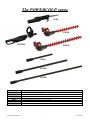
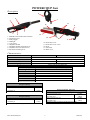
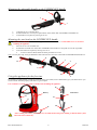
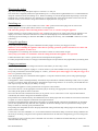
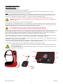
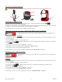
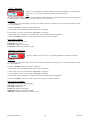
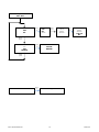
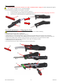
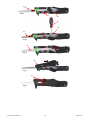
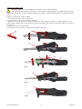
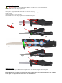
ORIGINAL PSTH10 - SC30 USER GUIDE Réf. NPSTH10/SC30 Indice 02. The POWERCOUP range SC30 TH380 PSTH10 TH540 R500 R1000 R1500 Reference PSTH10 SC30 TH380 TH540 R500 R1000 R1500 Description Universal POWERCOUP range handle. Saw head. Hedge-trimmer with adjustable head, blade length 380 mm (14.96 inches). Hedge-trimmer with adjustable head, blade length 540 mm (21.26 inches). Carbon extension, length 500 mm (19.7 inches). Carbon extension, length 1000 mm (39.4 inches). Carbon extension, length 1500 mm (59.1 inches). Ref. NPSTH10/SC30 1 Index 02. Contents Description ........................................................................................................................................................................... 3 Characteristics: .................................................................................................................................................................... 3 Mounting the adjustable handle on the POWERCOUP handle ............................................................................................. 4 Mounting the saw head on the POWERCOUP handle .......................................................................................................... 4 Using the appliance for the first time .................................................................................................................................... 4 Wearing the jacket ................................................................................................................................................................ 5 Switching on ......................................................................................................................................................................... 5 Using the appliance .............................................................................................................................................................. 5 Usage precautions ................................................................................................................................................................ 5 Recharging the battery .......................................................................................................................................................... 7 Example of charging ............................................................................................................................................................. 8 How the control box operates ............................................................................................................................................... 9 Switching on the control box ................................................................................................................................................. 9 Changing the display direction: RIGHT-HANDED/ LEFT-HANDED .................................................................................. 9 Resetting “user” statistics to zero ......................................................................................................................................... 9 “User” statistics ................................................................................................................................................................. 10 “Factory” statistics ............................................................................................................................................................ 10 Control box operating graph .............................................................................................................................................. 11 Saw orientation ................................................................................................................................................................... 13 Saw head maintenance – Changing the blade ..................................................................................................................... 13 Adjusting blade play ........................................................................................................................................................... 15 Servicing - Lubrication ....................................................................................................................................................... 16 Annual service .................................................................................................................................................................... 16 Pole .................................................................................................................................................................................... 17 Safety instructions ............................................................................................................................................................... 18 Guarantee conditions .......................................................................................................................................................... 19 Note: For using a POWERCOUP hedge-trimmer, please see the instructions supplied with the hedgetrimmer head (ref. NTH540/380). Environmental protection: Follow the specific instructions for waste elimination in your country. Electrical appliances should not be thrown in the bin. The device, accessories and packaging should be recycled. Ask your specialist INFACO retailer for the latest information on eco-compatible waste elimination. Ref. NPSTH10/SC30 2 Index 02. POWERCOUP Saw Description 6 4 7 3 11 13 8 1 2 5 14 1: POWERCOUP handle (Ref. PSTH10). 2: Actuating trigger. 3: Safety trigger. 4: LED light. 5: 3-pin socket. 6: Adjustable handle. 7: Adjustable handle restraining lever. 8: Adjustable saw head (Ref. SC30). 9: Saw head restraining lever. 12 10 9 10: Removable cover. 11: Removable cover screw. 12: Hook. 13: Saw blade. 14: Blade cover. Characteristics: Reference Power Weight Size (LxWxH) in mm Cutting capacity Blade speed PSTH10 SC30 1400W Max 2 kg 400 550 x 200 x 240 700 g 450 x 70 x 130 100 mm maximum 1700 in and out movement /min Autonomy according to cutting diameter (Electrocoup 3.2 Ah battery) Cutting diameter Number of cuts 1200 3 cm 800 4 cm 600 5 cm 400 6 cm 300 7 cm 200 8 cm Powercoup PSTH10, Saw SC30 Charge functioning Vibration emission value determined according to EN 12096 Measured vibration emission value, ahc,w 16,3 m/s² Powercoup PSTH10, Saw SC30 No load functioning Sound emission value determined according to NF EN 60745-1:2009 Acoustic power level, LwA 97 dB(A) Uncertainty, K 1,6 m/s² Declaration values according to NF EN 60745-2-15:2009 Powercoup PSTH10, Saw SC30, Extension R1500 Charge functioning Vibration emission value determined according to EN 12096 Measured vibration emission value, ahc,w 12,6 m/s² Uncertainty, K 1,5 m/s² Declaration values according to NF EN 60745-2-15:2009 Ref. NPSTH10/SC30 3 Uncertainty KwA Sound pressure level, LpA 3 dB(A) 86 dB(A) Uncertainty, KpA Declaration values according to NF EN 60745-2-15:2009 3 dB(A) Index 02. Mounting the adjustable handle on the POWERCOUP handle 6 1 7 123- Unlock lever no.7 as shown above. Position handle no.6 to suit your requirements on the carbon tube of POWERCOUP handle no.1. Lock handle no.6 in place by moving lever no.7. Mounting the saw head on the POWERCOUP handle Disconnect socket no.5 before assembling saw head no.8 on handle no.1. Attach blade cover no.14 before handling the appliance. 123- Move lever no.9 on saw head no.8. Positionner saw head no.8 on the tube of POWERCOUP handle no.1 and push it on as far as possible. Lock saw head no.8 in place by moving lever no.9. To remove the saw head, follow the same procedure in reverse. Note: On new parts only, it may be difficult to slide saw head no.8 on to the carbon tube of POWERCOUP handle no.1. 8 1 14 4 3 9 5 Using the appliance for the first time 2 We strongly recommend that you ask for assistance from your retailer, who is authorised to give you all the advice you need to use the machine properly and achieve a good output. It is essential to read this user guide carefully before handling the appliance. 18 16 Control box Battery 15 19 17 22 20 21 If it is raining, the battery jacket must be worn underneath waterproof clothing so that the battery unit and control box remain dry. Ref. NPSTH10/SC30 4 Index 02. Wearing the jacket Slip on the shoulder straps and adjust straps no.16 and no.17 to suit you. The control box is originally mounted on right-hand strap no.17 of the jacket for right-handed user. For a left-handed user, unclip the control box from its mounting no.18. Remove mounting no.18 from the right-hand strap and slip it on the the left-hand strap. Clip the control box on to mounting no.18, turning the box so that the spiral cable is at the front. For the left-hand version, you should also change the control box display direction (see page 8). Switching on Make sure that switch no.19 on the control box is in the “OFF” position and connect plug no.20 to socket no.22. Connect plug no.21 on the spiral cable to socket no.5 on the appliance. N.B. follow the guide pin when connecting. Remove blade cover no. 14 before using the appliance. Position switch no.19 on the control box in the “ON” position only when you are ready to start using the appliance. The display screen on the control box and LED no.4 on the saw should light up. You must follow the correct order for connecting up and switching on, otherwise fault “D11” is displayed. If necessary, rearm “ON/OFF” switch no.19 on the control box. Using the appliance Every time you use the appliance, press and hold down safety trigger no.3 then press trigger no.2 twice. Whenever you are handling the appliance other than for pruning operations, position switch no.19 on “OFF” and disconnect the appliance at socket no.5. If the appliance is not working, switch off the control box at switch no.19 then switch on again. Always keep your hands at a safe distance from the cutting head when the appliance is in operation. It takes about three days to learn to get the best use and output from this appliance. For safety and practical reasons, we strongly recommend using the case provided for carrying the battery in working areas. Usage precautions Make sure your battery has been charged for at least 5 hours before you start a day’s work. Always disconnect the appliance at plugs no. 5 and 21 whenever you wish to handle it in any way other than for pruning. Every time you disconnect and reconnect plugs no. 5 and 21, you MUST press safety trigger no.3 and press trigger no.2 twice to re-prime the safety system. Never disconnect plug no.5 at the bottom of the appliance or stop the control box when you are using operating trigger no.2 of the appliance . If the appliance detects a discharged battery, the machine stops and LED no.4 flashes (indicating a fault) once every halfsecond. To re-prime it, switch the control box off and back on again using switch no.19. As soon as you feel that there is a lack of power, stop work and put your battery on charge. Do not leave the appliance on the ground and do not expose it to bad weather. Do not force the tool. Use the appropriate tool for the job you are doing. The appropriate tool will do the job better and more safely at the speed for which it was built. Do not use the tool if the switch does not allow you to go from “On” to “Off” and vice versa. Any tool that cannot be controlled by the switch is dangerous and should be repaired. Keep tools that are switched off away from children and do not allow people who do not know the tool or these instructions to operate it. Tools are dangerous in the hands of inexperienced users. Keep the tool well maintained. Check that moving parts are not badly aligned or obstructed, and that there are no broken parts or other problem that may affect the tool’s operation. If the tool is damaged, have it repaired before using it again. Many accidents are caused by poorly maintained tools. Keep cutting tools sharpened and clean. Properly maintained cutting tools with sharp cutting edges are less likely to block and are easier to control. Use the tool, accessories and blades, etc., in accordance with these instructions, taking account of working conditions and the work you are doing. Using the tool for operations other than those for which it is designed may give rise to dangerous situations. Do not place any part of your body close to the blade. Do not remove cut material or hold the material you wish to cut while the blades are moving. Ref. NPSTH10/SC30 5 Index 02. Make sure that the switch is in the “Off” position when you remove material that has got stuck. A moment’s inattention while using the appliance can lead to serious physical injury. Carry the appliance by the handle, with the cutting blade switched off. When transporting or storing the appliance, always cover the cutting system with its protective cover. Proper handling of the appliance will reduce the likelihood of physical injury caused by the cutting blades. Keep the electrical supply lead well away from the cutting area. During usage, the lead may be hidden in shrubbery and be accidentally cut by the blade. Ref. NPSTH10/SC30 6 Index 02. Recharging the battery Charge indicator lights Fixed orange: battery on charge. Fixed green: battery charged (remains on top-up charge). Fixed orange light for 2 seconds when the 2nd battery is connected: signals that it has been detected by the charger. Note: the order of charge depends on the order of connection. To charge your battery belt, connect charger no.23 (741C1) to the 230V 50Hz mains supply on well-ventilated premises free of inflammable products and sources of ignition. The battery must not be covered or close to a heat source. The temperature on the premises should be between 10° C and 25° C and there should be no damp. For safety reasons and to ensure that your battery belt remains in good working order, it is very important to recharge it in a well-ventilated area and not inside its carry-case to avoid overheating (see diagram page 7). Connect plug no.22 on the battery to socket no.24 on the charger. The charger starts working automatically as soon as the battery is connected. Indicator light no.26 lights up fixed orange throughout charging. When your battery is fully charged, indicator light no.25 lights up green. From this moment on, the charger automatically provides a top-up charge, which keeps the battery charged. It is not advisable to leave your battery on top-up charge for more than 48 hours. It is essential to recharge the battery at least every 2 months during the off-season. You also have the option of connecting a 2nd battery to socket no.27 on the charger. When a 2nd battery is connected, orange indicator light no.29 lights up for 2 seconds to signal that the charger has detected the 2nd battery. At that moment, the battery is awaiting charging. When the first battery is charged, the second battery takes over. Once the second battery is fully charged, green indicator light no.28 lights up and the charger supplies only a top-up charge. If the indicator lights on your charger do not light up, leave your battery(ies) connected and, at the same time, disconnect and re-connect mains plug no.23 (230 V) on your charger until the orange indicator light(s) light(s) up. When the battery is charged, we recommend that you disconnect plug no.23 from the charger to avoid damage caused by a possible power surge in your electricity supply. The use of a charger or battery other than one made by us is strictly forbidden as this runs the risk of causing a breakdown or an accident and would therefore lead to the manufacturer’s guarantee being cancelled. For information, battery belt charge time is approximately 5 hours (3 hours for the SL model). The ELECTROCOUP charger must only be used with the ELECTROCOUP batteries provided, which are NiMh and NiCd 48 Volt. It is strictly prohibited to use the ELECTROCOUP charger for recharging non-rechargeable batteries. This would cause serious damage. 26 29 23 25 28 24 22 27 Charger (741C1) Ref. NPSTH10/SC30 7 Index 02. Safety instructions for batteries: Never try to open them for any reason whatsoever. Never place them in contact with water. Make sure they are clean and dry before putting them on charge. Environmental protection instructions: Batteries designated by the abbreviation NiCd contain Cadmium and NiMh contain Metal hydride. A worn or faulty battery must be recycled in accordance with directive 91/157/EEC. Do not throw a battery out with the household rubbish, or on to flames or into water. Do not open the battery/ appliance. Leave the battery/ appliance with an approved ELECTROCOUP retailer Example of charging Think about it ! Recharge your battery every 2 months during the off-season. USEFUL TIP: Note your recharging dates on a calendar hanging close to your charging point. Ref. NPSTH10/SC30 8 Index 02. How the control box operates To prevent the battery from discharging, remember to disconnect the control box at plug no.20. 30 19 20 21 22 Switching on the control box When the control box is switched on, using switch no.19, the screen shows the state of the battery . The battery level is shown by a 4-level bar graph. You need to use the appliance for approximately 5 minutes to obtain a display of the actual battery level. This is calculated according to average use and may be different when the appliance is switched on. Use push-button no.30 on the control box to change from mode to mode. Changing the display direction: RIGHT-HANDED/ LEFT-HANDED P02 R/L This programme is used to reverse the control box display direction for a left-handed user. Procedure: 1- Connect plug no.22 on the battery to socket no.20 on the control box. Connect plug no.21 on the spiral cable to socket no.5 on the appliance. 2- Rearm “ON/OFF” switch no.19 on the control box. 3- The battery level “ ” is displayed (if the battery level is not displayed immediately, press button no.30 regularly until ” ” is displayed). 4- Press button no.30 for 5 seconds until “P02 R/L” is displayed. 5- Press button no.30 for 3 seconds to enter the programme: “P02 R/L” flashes. 6- Press button no.30 once to changer the display direction. 7- Press button no.30 for 3 seconds to confirm the display direction:”P02 R/L OK” is displayed. Resetting “user” statistics to zero P03 DELETE This programme is used to reset “user” statistics to zero (number of cycles, blockage, usage time, etc.). Procedure: 1- Connect plug no.22 on the battery to socket no.20 on the control box. Connect plug no.21 on the spiral cable to socket no.5 on the appliance. 2- Rearm “ON/OFF” switch no.19 on the control box. 3- The battery level “ repeatedly until ” ” is displayed (if the battery level is not displayed immediately, press button no.30 ” is displayed). 4- Press button no.30 for 5 seconds until “P02 R/L” is displayed. 5- Press button no.30 once until “P03 DELETE” is displayed. 6- Press button no.30 for 3 seconds to confirm the reset to zero: “P03 DELETE OK” is displayed. Ref. NPSTH10/SC30 9 Index 02. “User” statistics U01 CYCL XXX When in use, the appliance memorises different types of data (number of cycles, blockage, usage time, etc.). You may consult these statistics via the control box. Note: The digital display control box is only a reader interface: all the statistics are stored in the electronic card on the appliance. You have the option of putting the “user” statistics back to zero (see above). Procedure: 1- Connect plug no.22 on the battery to socket no.20 on the control box. Connect plug no.21 on the spiral cable to socket no.5 on the appliance. 2- Rearm “ON/OFF” switch no.19 on the control box. 3- Press button no.30 repeatedly until the symbol “%” is displayed. 4- Press button no.30 for 5 seconds until “U01 CYCL” is displayed. 5- Press button no.30 repeatedly to consult the other statistics memorised by the appliance. 6- Rearm “ON/OFF” switch no.19 on the control box to get out of “user” statistics. List of “user” statistics: U01 CYCL: Number of cycles. U02 TIME: Usage time. U03 BCYC: Number of blockages U04 TEMP: Number of temperature faults. “Factory” statistics S01 NUM XXXXXX “Factory” statistics are reset to zero every time the appliance is returned to the factory. Procedure: 1- Connect plug no.22 on the battery to socket no.20 on the control box. Connect plug no.21 on the spiral cable to socket no.5 on the appliance. 2- Rearm “ON/OFF” switch no.19 on the control box. 3- Press button no.30 repeatedly until the symbol “ %” is displayed. 4- Press button no.30 for 5 seconds until “U01 CYCL” is displayed. 5 - Press button no.30 for 3 seconds until “S01 NUM» is displayed. 6- Press button no.30 repeatedly to consult the other statistics memorised by the appliance. 6- Rearm “ON/OFF” switch no.19 on the control box to get out of “factory” statistics. List of “factory” statistics: S01 NUM: Serial number of the appliance. S02 CYCL: Number of cycles. U02 TIME: Usage time. U03 BCYC: Number of blockages. S05 TEMP: Number of temperature faults. S06 SOFT: Software version in the electronic card. Ref. NPSTH10/SC30 10 Index 02. Control box operating graph «ON/OFF» SWITCH Battery level Press 5s Programme P02 ; P03 Short press Press 5s % «User» statistics Short press Ref. NPSTH10/SC30 11 Index 02. Programme P02 ; P03 Reverse display direction P02 R/L Press 3s Short press P02 R/L flashes Choose display direction Press 3s Confirm display direction P02 OK R/L Short press Reset «user» statistics to zero Press 3s P03 DELETE Delete «user» statistics P03 OK DELETE Short press «User» statistics Ref. NPSTH10/SC30 Press 3s «Factory» statistics 12 Index 02. Saw orientation Position switch no.19 on the control box on “OFF” and DISCONNECT plug no.5 before changing the angle of the saw head. Use blade cover no.14 before handling. The saw head may be angled in two positions. To do this: 123- Loosen wing nut no.31: you do not need to remove it. Using your hand, angle the hand in the required position (Take care to avoid the cutting edge of the blade) Once you have selected the position, tighten wing nut no.31. 14 31 Saw head maintenance – Changing the blade To change the blade, disconnect plug no. 5. Use blade cover no.14 before handling. 1- Pivot the two screws no.32 by a quarter turn. 2- Incline hood no.33 then move to the left to remove it. 3- Place blade no.13 in the closed position. Using screwdriver no.34, lift under rod no.35 then move it upwards. 4- Remove blade no.13. If necessary, clean and lubricate around rollers no.36 and 37 and gear rim no.38 (see page 15). 5- Place the new blade on the saw head. Using screwdriver no.34, put rod no.35 in place on the new blade. 6- Hand-operate the saw head for a few moments to check that it is working correctly. 7- Position hood no.33 on the saw head. 8- Pivot the two screws no.32 by a quarter turn to lock the hood in place. 32 14 Fig. 1 33 Fig. 2 35 13 Fig. 3 Ref. NPSTH10/SC30 34 36 13 Index 02. 13 Fig. 4 37 38 34 35 13 Fig. 5 13 Fig. 6 33 Fig. 7 32 Fig. 8 Ref. NPSTH10/SC30 14 Index 02. Adjusting blade play Disconnect plug no. 5 to adjust blade play. Use blade cover no.14 before handling. Check the blade adjustment every morning. To do this, hold the end of the blade in your hand and check the play upwards/downwards (Fig.1). There should be as little play as possible to ensure that the blade does not jump out from the rollers. If there is too much play, adjust as follows: 1- Pivot the two screws no.32 by a quarter turn. 2- Incline hood no.33 then move to the left to remove it. 3-Adjust the two moving rollers no.37 using Allen key no.39. Loosen and move rollers no.37 towards blade no.13 and reduce the play. Tighten rollers no.37.If necessary, lubricate the teeth of gear rim no.38 and around rollers no.36 and no.37 (see page 15). 4- Position hood no.33 on the saw head. 5- Pivot the two screws no.32 by a quarter turn to lock the hood in place. 32 14 Fig. 1 33 Fig. 2 37 39 38 Fig. 3 33 Fig. 4 32 Fig. 5 Ref. NPSTH10/SC30 15 Index 02. Servicing - Lubrication Disconnect plug no. 5 prior to lubricating the blade. Use blade cover no.14 before handling. 1- Pivot the two screws no.32 by a quarter turn. 2- Incline hood no.33 then move to the left to remove it. 3-If necessary, clean around rollers no.36 and no.37 and gear rim no.38. 4-Using universal grease, lubricate around rollers no.36 and no.37, the pinion/gear rim unit and the edge of the blade (area marked in blue). 7- Position hood no.33 on the saw head. 5- Pivot the two screws no.32 by a quarter turn to lock the hood in place. 32 14 Fig. 1 33 Fig. 2 38 37 Fig. 3 36 33 Fig. 4 32 Fig. 5 Annual service Have the tool serviced by an official INFACO repairer using only identical, original replacement parts. This will ensure that the tool remains safe to use. During the off-season, remember to recharge your battery at least once every two months and store your appliance in a dry place at a temperature of between 10°C and maximum 25°C. Ref. NPSTH10/SC30 16 Index 02. Pole Disconnect plug no. 5 prior to all operations. Use blade cover no. 14. You have the option of adding extensions to increase the cutting height of POWERCOUP tools (optional): 1Move lever no. 9 to remove the saw head. 2Move lever no. 7 then remove handle no. 6. 3Position the pole in the place of the head then move lever no. 40 to lock it in place. 4Position the saw head on the end of the pole and lock it in place. Note: You have the option of mounting handle no. 6 on the extension. 6 14 9 7 6 9 7 40 Reference R500 R1000 R1500 Ref. NPSTH10/SC30 Carbon pole Length 500 mm – 19.7 inches 1000 mm – 39.4 inches 1500 mm – 59.1 inches 17 Weight 440 g 620 g 820 g Index 02. Safety instructions WARNING. Read all safety warnings and all instructions. Failure to abide by warnings and instructions could lead to an electric shock, fire and/or serious injury. Keep all safety warnings and instructions so that you can refer to them at a later date. The term “tool” in the warnings refers to your electrical tool run off the mains supply (with supply lead) or your electrical battery-operated tool (without a supply lead). Safety measure: Whenever you are handling the appliance other than for pruning operations, place switch no. 19 on the control box in the “OFF” position and disconnect the appliance at plug no. 5. Cover the blade with its protective cover every time you handle or transport the appliance. Keep the working area clean and well lit. Accidents often occur in untidy, dark areas. Never use the appliance at night or in poor light without setting up extra lighting. Do not operate electrical tools in an explosive atmosphere, e.g. in the presence of inflammable liquids, gas or dust. Electrical tools produce sparks that may ignite dust or fumes. Keep children and other people present at a safe distance when using the tool. Distractions may make you lose control of the tool. Use the appropriate, adapted means (scaffolding, platform, etc.) when working at a height. Do not try to cut wood of too large a diameter or materials other than wood (tree branches only). The electrical tool’s connectors must be adapted to the base. Never modify the connector in any way whatsoever. Never use adaptors with earthed tools. Unmodified connectors and adapted bases will reduce the risk of electric shock. Do not expose tools to rain or damp conditions. Water penetration inside the tool will increase the risk of electric shock. Treat the electrical lead with care. Never use it to carry, pull or disconnect the tool. Keep the lead away from heat, lubricants, sharp edges and moving parts. Damaged or tangled leads increase the risk of electric shock. Never carry the charger by the lead and do not pull the lead to disconnect the plug. . Keep the lead away from heat, oil and sharp edges. Never place the charger in contact with water. If your charger lead is damaged, you should change it using an original lead or unit from the INFACO factory or from an approved ELECTROCOUP retailer. Never leave your battery on charge for more than 24 hours. Do not charge the battery in the case: allow air to circulate around it. The appliance must be disconnected at rear plug no. 5 for the following operations: - When you are putting on or taking off the battery-carrier jacket. When mounting, removing or lubricating the blade. When changing the cutting head. When servicing or repairing the appliance. Take care to avoid the cutting edge of the blade when removing and adjusting it. When the appliance is in operation, always keep your hands away from the cutting head. Avoid switching on the machine unexpectedly. Make sure the switch is in the “Off” position before connecting the tool to the mains supply and/or battery block, picking it up or carrying it. Accidents may be caused by carrying tools with a finger on the switch or connecting tools to the mains supply when the switch is in the “On” position. Remove all adjustment keys before switching to tool on. A key left attached to a rotating part of the tool could injure someone. Remain vigilant, watch what you are doing and show common sense in the way in which you use the tool. Do not use a toll when you are tired or under the influence of drugs, alcohol or medication. A moment’s lack of attention when using a tool can lead to serious physical injury. Do not rush. Maintain a suitable position and good balance at all times. This allows you to control the tool better in unexpected situations. Use safety equipment. Always wear eye protection. Safety equipment such as dust masks, non-slip safety shoes, helmets and ear protection used in appropriate conditions will reduce the likelihood of physical injury. Dress suitably. Do not wear loose-fitting clothing or jewellery. Keep your hair, clothing and gloves well away from moving parts. Loose-fitting clothing, jewellery or long hair may get caught up in moving parts. Ref. NPSTH10/SC30 18 Index 02. Do not leave the appliance within reach of children or visitors. Children should be supervised to ensure that they do not play with the appliance. When using the appliance, keep both feet on the ground and remain firmly balanced. The appliance is not designed to be used by people (including children) with reduced physical, sensory or mental capacity, or by people with no expoerience or knowledge, unless they are supervised or given prior instruction in the use of the appliance by a person responsible for their safety. Read the user instructions carefully, especially the safety instructions. You MUST wear a helmet, eye protection and hearing protection. N.B. The extensions are made of carbon, which conducts electricity. Do not use them near electricity supply points or electrical wires. N.B. Do not place any part of your body close to the blade. Do not remove cut material or hold the material you wish to cut while the blades are moving. Guarantee conditions POWERCOUP appliances are guaranteed for one year against all faults and manufacturing defects. The guarantee is not valid unless the guarantee card has been duly filled in and returned to the address printed on it. If the guarantee card has not been returned at the time of the guarantee request, the ex-works departure date will be used to determine the guarantee period. INFACO may not be held liable for any appliances sold by distributors more than a year after they have left the factory. This guarantee covers normal usage of the appliance and does not cover: - damage caused by poor maintenance or a lack of maintenance, - damage caused by incorrect usage, - damage caused by normal wear and tear, - appliances that have been dismantled by unauthorised repairers, - outside agents (fire, flood, lightning, etc...), - impacts and their consequences, - appliances for which the guarantee card has not been returned at the time of purchase, - appliances used with a battery or charger other than a POWERCOUP brand.. In no circumstances will the guarantee give rise to compensation for the fact that the appliance is immobilised while it is being repaired. Repair or replacement during the guarantee period does not give the right to an extension or renewal of the initial guarantee. The guarantee covers factory labour costs (on the condition that the appliance has always been serviced) but does not necessarily apply to retailer labour costs. The guarantee on the appliance will no longer be valid if the appliance has been worked on by anyone other than an approved POWERCOUP. We strongly recommend that, in the event of a breakdown, users of POWERCOUP equipment should contact the retailer who sold the machine or our after-sales department on (+33) 05 63 33 91 49. To avoid disputes, please note the following procedure: - for equipment covered by the guarantee, please send it to us carriage paid and we will return it at our expense, - for equipment not covered by the guarantee, and which has not been serviced during the previous off-season, please send it to us carriage paid and we will return it at your expense, cash on delivery. We will send you an estimate if the cost of the repair is more than 80 € ex-VAT. We confirm that the battery has a life of five seasons. If the battery does not last for five seasons, we will supply a new battery on a pro rata basis (except for the F3010 SL model, which has a life of 3 seasons). Example: Price of the new battery divided by 5 (life span) and multiplied by the number of seasons used. Ref. NPSTH10/SC30 19 Index 02. RETAILER SECTION The retailer should keep this section Serial no.: ……………………………………………………………………………………………………………………. Name: …………………………………………………………………………………………………………………........... First name: ………………………………………………………………………………………………………………………... Company name: …………………………………………………………………………………………………………............ Full address: …………………………………………………………………………………………………………….. ………………………………………………………………………………………………………………………………….. Town:…………………………………………………………………………………………………………………………… Postcode: ……………………………. CUSTOMER SIGNATURE Telephone: ……………………………… Date of purchase: . . . . . . . / . . . . . . . / . . . . . . . Comment:……………………………………………………………….. RETURN THIS COUPON TO INFACO AS SOON AS YOU HAVE PURCHASED THE APPLIANCE RETURN this form IMMEDIATELY, duly filled in in CAPITAL LETTERS to ensure full guarantee cover. Name: ………………………………………………………. First name:………………………………………................... Company name: …………………………………………………………………………………………………………............ Full address: …………………………………………………………………………….................................................. ………………………………………………………………………………………………………………………………….. Postcode: ………………….. Town:…………………………………………………………………………............... Telephone:……………………. Fax: ……………………………. Mobile: ……………………… ❑ Arboriculture E-mail: ………………………. ❑ Tree pruning Date of purchase: . . . . . . . / . . . . . . . / . . . . . . . ❑ Winegrowing Serial no.: . . . . . . . . . . . . . . . . . . ❑ Parks and gardens RETAILER STAMP Comments: ……………………………………………………………. Ref. NPSTH10/SC30 20 Index 02. Serial no.: ...................................... out bon non parfaitement rempli and non envoyé dans les délais ne pourra être pris en compte RETAILER To be kept by the retailer for the INFACO customer file Ref. NPSTH10/SC30 21 Index 02. EQUIPMENT MANUFACTURED IN FRANCE Manufacturer: INFACO S.A.S. - 81140 CAHUZAC-SUR-VÈRE (FRANCE) Type: POWERCOUP Ref: PSTH10 – SC30 Battery weight: 2, 400 g Weight of wiring + wired control box + battery jacket: 500 g Appliance power: 1400W Charger model: 741C1 Charger power: 65 W Battery voltage: 48 Volts Primary charger voltage: 230 Volts 50 Hz Secondary charger voltage: 56 Volts DC 1A DC Max. These specifications are given for guidance only. They are in no circumstances contractually binding and may be modified for the purpose of improving the product without prior notice. Patented equipment. Technical information or After-Sales: Ref. NPSTH10/SC30 22 Index 02. DECLARATION OF CONFORMITY (CE) INFACO S.A.S. declares that the new equipment designated below: POWERCOUP electric saw brand name: INFACO - model: POWERCOUP Year of manufacture: Serial no: complies with the provisions of the directives for : - “appliances” (directive 2006/42/CEE) - Directive 200/14/EC « on the noise emission by equipment for use outdoors » (order of 18 march 2002) modified by the directive 2005/88/EC (order of 22 may 2006). Powercoup PSTH10, Saw SC30 Acoustic power level, LwA Sond pressure level, LpA - 97 dB(A) 86 dB(A) “electric chargers” (directive 2004/108/CEE) and with national legislation adapting them. The equipment also complies with the provisions of the following European directives: NF EN 61000-3-2 NF EN 61000-4-2 NF EN 61000-4-3 NF EN 61000-4-4 NF EN 61000-4-5 NF EN 61000-4-6 NF EN 61000-4-11 NF EN 55014-1 NF EN 550014-2 NF EN 55022 NF EN 55011 Signature: Signed in: CAHUZAC SUR VÈRE Mr. Daniel DELMAS, CEO of INFACO Ref. NPSTH10/SC30 23 Index 02.