1
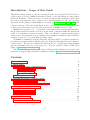
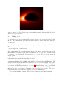
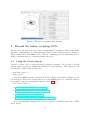
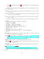
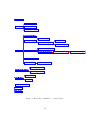
Quick User Guide for GYOTO
Updated June 20, 2014
1
Introduction - Scope of this Guide
This Guide aims at giving a general presentation of the General relativitY Orbit Tracer
of Observatoire de Paris, GYOTO (pronounced [dZIoto], as for the Italian trecento painter
Giotto di Bondone). This text is not a lecture on ray-tracing techniques and is only
devoted to presenting the code so that it can be quickly handled by any user. Readers
interested in the physics behind GYOTO are referred to Vincent et al. (2011, 2012, and
references therein). The aim of this Guide is also to present the code in sufficient details
so that people interested to develop their own version of GYOTO can do it easily.
GYOTO is an open source C++ code with a Yorick plug-in that computes null and timelike geodesics in the Kerr metric as well as in any metric computed within the framework
of the 3+1 formalism of general relativity. This code allows to compute mainly images
and spectra of astrophysical sources emitting electromagnetic radiation in the vicinity of
compact objects (e.g. accretion disks or nearby stars).
As GYOTO is continually evolving, this guide will (hopefully) be regularly updated to
present the new functionalities added to the code. However, this guide does not constitute
a full reference. The reference manual is built from the C++ header files using doxygen
into the doc/html/ directory of the source tree. It is also available online (rebuilt every
night) at http://gyoto.obspm.fr/.
The reader is strongly encouraged to give feedback on this Manual, report typos, ask
questions or suggest improvements by sending an email to [email protected]
Contents
1 Installing GYOTO
4
2 Basic usage
2.1 Using the gyoto command-line tool
2.1.1 XML input file . . . . . . .
2.1.2 Calling gyoto . . . . . . . .
2.1.3 FITS output file . . . . . . .
2.2 The gyotoy interface . . . . . . . .
.
.
.
.
.
4
4
4
6
7
7
3 Beyond the basics: scripting GYOTO
3.1 Using the Yorick plug-in . . . . . . . . . . . . . . . . . . . . . . . . . . .
3.2 Interfacing directly to the GYOTO library . . . . . . . . . . . . . . . . . . .
8
8
9
4 Choosing the right integrator
4.1 The Boost integrators . . . . . . . . . . . . . . . . . . . . . . . . . . . .
4.2 The Legacy integrator . . . . . . . . . . . . . . . . . . . . . . . . . . . .
4.3 Integrator comparison . . . . . . . . . . . . . . . . . . . . . . . . . . . .
9
11
11
12
5 GYOTO architecture
5.1 GYOTO base classes . . . . . . . . . . . . . . . . . . . . . . . . . . . . . .
5.2 A typical GYOTO computation . . . . . . . . . . . . . . . . . . . . . . . .
13
13
15
2
.
.
.
.
.
.
.
.
.
.
.
.
.
.
.
.
.
.
.
.
.
.
.
.
.
.
.
.
.
.
.
.
.
.
.
.
.
.
.
.
.
.
.
.
.
.
.
.
.
.
.
.
.
.
.
.
.
.
.
.
.
.
.
.
.
.
.
.
.
.
.
.
.
.
.
.
.
.
.
.
.
.
.
.
.
.
.
.
.
.
.
.
.
.
.
.
.
.
.
.
6 Computing an image or a spectrum
6.1 The Screen . . . . . . . . . . . . .
6.2 Computing an image . . . . . . . .
6.3 Computing a spectrum . . . . . . .
in the
. . . .
. . . .
. . . .
Kerr metric
. . . . . . . .
. . . . . . . .
. . . . . . . .
with GYOTO
. . . . . . . . .
. . . . . . . . .
. . . . . . . . .
15
15
16
16
7 GYOTO in numerical metrics
17
8 Extending GYOTO
8.1 Writing a plug-in . . . . . . . . . . . . .
8.2 Adding a new metric (Metric) . . . . . .
8.3 Adding a new spectrum (Spectrum) . . .
8.4 Adding a new astrophysical target object
8.5 Using your new plug-in . . . . . . . . . .
8.6 Quality assurance . . . . . . . . . . . . .
17
18
18
20
20
20
21
3
. . . . . .
. . . . . .
. . . . . .
(Astrobj)
. . . . . .
. . . . . .
.
.
.
.
.
.
.
.
.
.
.
.
.
.
.
.
.
.
.
.
.
.
.
.
.
.
.
.
.
.
.
.
.
.
.
.
.
.
.
.
.
.
.
.
.
.
.
.
.
.
.
.
.
.
.
.
.
.
.
.
.
.
.
.
.
.
.
.
.
.
.
.
1
Installing GYOTO
GYOTO is freely available at the URL http://gyoto.obspm.fr/. This URL hosts the
online manual of GYOTO, with installation instructions and brief descriptions of the code
architecture.
GYOTO is version-controlled with the git software that you should install on your
machine. Before uploading the code, be sure that the xerces-c3 (or xercesc3 depending
on the architecture) and cfitsio libraries are installed on your system: GYOTO won’t
compile without these. It is also better (but not required) to install the udunits2 library.
Once this is done, just type on a command line
git clone git://github.com/gyoto/Gyoto.git
which will create a Gyoto repository. It contains directories bin, lib, include, doc,
yorick containing respectively the core code and executable, the .C source files, the .h
headers, the documentation and Yorick plug-in related code.
In the Gyoto repository, use the standard
./configure; make; sudo make install
commands to build the code.
In case of problems, have a look at the INSTALL file that gives important complementary informations on how to install GYOTO.
2
2.1
Basic usage
Using the gyoto command-line tool
The most basic way of using GYOTO is through the gyoto command-line tools. It relies
on two kinds of files: an XML file containing the inputs and a FITS file containing the
outputs.
2.1.1
XML input file
You can find examples of XML input files in doc/examples/. Let us consider the computation of the image of a standard Page-Thorne accretion disk in Boyer-Lindquist coordinates, described in example-page-thorne-disk-BL.xml.
If you are not familiar with XML language, just remember that an XML file is
made of several fields beginning with the <Field Name> and ending with </Field
Name>. One field can have sub-fields, defined with the same symbols. For instance
in example-page-thorne-disk-BL.xml, there is one global field, Scenery, describing
the scenery that will be ray-traced, with a few sub-fields: Metric describing the metric
used for the computation, here the Kerr metric in Boyer-Lindquist coordinates; Screen
describing the observer’s screen properties; finally Astrobj describing the astrophysical
object that will be ray-traced, here a Page-Thorne accretion disk. All the parameters in
this input file can be changed to specify a new scenery.
Let us present in details the example-page-thorne-disk-BL.xml file:
4
<?xml version="1.0" encoding="UTF-8" standalone="no"?>
<Scenery>
The following lines specify the metric: it is the Kerr metric, expressed in BoyerLindquist coordinates, with spin 0 (so the Schwarzschild metric here!):
<Metric kind = "KerrBL">
<Spin>
0.
</Spin>
</Metric>
The metric is now defined, let us describe the observer’s screen. The Position field
gives the screen’s 4-position in Boyer-Lindquist coordinates (t, r, θ, ϕ), angles in radians,
time and radius in geometrical units (i.e. units with c and G put to 1). The Time
field gives the time of observation. The FieldOfView is given in radians. The screen’s
Resolution is the number of screen pixels in each direction.
<Screen>
<Position>
1000.
100.
1.22
0.
</Position>
<Time unit="geometrical_time">
1000.
</Time>
<FieldOfView>
0.314159265358979323846264338327950288419716
</FieldOfView>
<Resolution>
32
</Resolution>
</Screen>
The screen is now defined. The following line describes the target object that will be
ray-traced:
<Astrobj kind = "PageThorneDisk"/>
Here the target object is very simple and requires no specifications. The Scenery is
now fully defined and the field can be closed
</Scenery>
This is the end of the XML input file!
5
Figure 1: Image of a Page-Thorne thin accretion disk around a Schwarzschild black hole,
with a 32 × 32 pixels screen.
2.1.2
Calling gyoto
We will now use the gyoto command-line tools to ray-trace the scenery described in this
XML file. The command-line options are documented in the usual UNIX-style manpage:
$ man gyoto
Once the XML input file is ready, the call to gyoto is done according to the following
line:
$ gyoto input.xml \!output.fits
where input.xml is the above mentioned XML file and output.fits is the name of the
FITS that will contain the result of the computation. The ! before the .fits file allows
to overwrite a pre-existing file. If you remove it, an error will occur if the .fits file
already exists.
The line above asks GYOTO to integrate a null geodesic from each pixel of the screen
backward in time towards the astrophysical object.
You can accelerate computations by using several cores on a computer using the
––nthreads=NCORES option. NCORES is the number of threads that GYOTO will use. The
optimal value is usually the number of hardware CPU cores on the machine. This option
can also be specified in the input file using the <NThreads> entity. This facility does
not work for LORENE-based metrics (see Sect. 7). Another cheap way of parallelising
the computation is to call several gyoto instances, running on different CPUs or even on
different machines, each instance computing only a portion of the image. This sort of
basic parrallelisation is, naturally, supported by all the GYOTO metrics.
You can ask GYOTO to compute only a fraction of the screen’s pixels by running:
$ gyoto --imin=IMIN --imax=IMAX --jmin=JMIN --jmax=JMAX input.xml \!output.fits
6
where IMIN, IMAX, JMIN, JMAX are the extremal indices of the pixels that will be
computed. For instance, to compute only the geodesic that hits the central pixel of a
32 × 32 screen, type:
$ gyoto --imin=16 --imax=16 --jmin=16 --jmax=16 input.xml \!output.fits
How to recombine the several output files into a single FITS file is left as an exercise
to the reader. It is easily done using any scientific interpreted language such as Yorick1
or Python2 .
Several other parameters can be overridden on the command-line. This includes the
position of the Screen and the observing time (–time=TIME), which is quite useful to
produce a movie.
2.1.3
FITS output file
Once the computation is performed, the output.fits file is created. You can visualise
it by using the ds9 software (http://hea-www.harvard.edu/RD/ds9/site/Home.html)
and simply running:
$ ds9 ouput.fits
For instance, if you use the example-page-thorne-disk-BL.xml as is, you will obtain
Fig. 1.
2.2
The gyotoy interface
The second most basic tool provided by GYOTO is gyotoy (Fig. 2). This is a graphical
user interface to visualize a single geodesic. See the README and INSTALL files for the
prerequisites. Once the installation is complete, your launch gyotoy as:
$ gyotoy
or, from the yorick/ sub-directory of the built source tree:
$ ./yorick -i gyotoy.i
followed, on the Yorick prompt, by:
> gyotoy
You can select a KerrBL metric and set the spin, or any other metric defined in an XML
file. As of writing, gyotoy assumes that the coordinate system is spherical-like. It should
work in Cartesian coordinates as well, but the labels will be odd. It is possible to select
which kind of geodesic to compute (time-like or light-like, using the Star or Photon radio
buttons), the initial position and 3-velocity of the particle, and the projection (a.k.a.
the position of the observer). The bottom tool bar allows selecting a few numerical
parameters such as whether or not to use an adaptive step. Menus allow saving or
opening the parameters as an XML file, exporting the geodesic as a text file, and saving
the view as an image file in various formats. The view can be zoomed and panned by
clicking in the plot area.
1
2
http://dhmunro.github.io/yorick-doc/
https://www.python.org/
7
Figure 2: The gyotoy graphical user interface.
3
Beyond the basics: scripting GYOTO
We have seen the two most basic ways of using GYOTO: computing a single frame using
the gyoto command-line tool, and exploring a single geodesic using the gyotoy interface.
There is much more that GYOTO can be used for: computing spectra, performing modelfitting, computing movies, evaluating lensing effects etc.
3.1
Using the Yorick plug-in
Yorick is a fairly easy to learn interpreted computer language. We provide a Yorick
plug-in which exposes the GYOTO functionalities to this language. This plug-in is self
documented: at the Yorick prompt, try:
> #include "gyoto.i"
> help, gyoto
A lot of the GYOTO test suite is written in Yorick, which provides many example code in
the various *.i files in the yorick/ directory of the GYOTO source tree. Another example
is provided by the gyotoy graphical interface (Sect. 2.2).
For Yorick basics, see:
• https://github.com/dhmunro/yorick;
• http://dhmunro.github.io/yorick-doc/;
• http://yorick.sourceforge.net/;
• http://www.maumae.net/yorick/doc/index.php.
As a very minimalist example, here is how to ray-trace an XML scenery into a FITS
file in Yorick:
8
$ rlwrap yorick
This launches Yorick within the line-editing facility rlwrap (provided separately). Then,
from the Yorick prompt:
>
>
>
>
>
#include "gyoto.i"
restore, gyoto;
sc = Scenery("input.xml");
data = sc(,,"Intensity");
fits_write, "output.fits", data;
or, in two lines:
> #include "gyoto.i"
> fits_write, "output.fits", gyoto.Scenery("input.xml")(,,"Intensity");
Likewise, to integrate the spectrum over the field-of-view:
>
>
>
>
>
>
>
>
#include "gyoto.i"
restore, gyoto;
sc = Scenery("input.xml");
data = sc(,,"Spectrum[mJy.pix-2]");
spectrum = data(sum, sum, );
freq = sc(screen=)(spectro=)(midpoints=, unit="Hz");
plg, spectrum, freq;
xytitles, "Frequency [Hz]", "Spectrum [mJy]";
3.2
Interfacing directly to the GYOTO library
The core functionality is provided as a C++ shared library, which is used both by the
gyoto command-line tool and the Yorick plug-in. You can, of course, interface directly
to this library. The reference is generated from the source code using doxygen in the
directory doc/html/. The application binary interface (ABI) is likely to change with every
commit. We try to maintain a certain stability in the application programming interface
(API), but the effort we put into this stability is function of the needs of our users. If
you start depending on the GYOTO library, please contact us ([email protected]):
we will try harder to facilitate your work, or at least warn you when there is a significant
API change.
4
Choosing the right integrator
Numerical ray-tracing can be very much time-consuming. In order to control the numerical errors in your application, it is wise to experiment with the numerical tuning
parameters. GYOTO provides several distinct integrators (depending on compile-time options):
• the Legacy integrator, the first to have been introduced;
9
• Boost3 integrators from the odeint4 library. In GYOTO, they are called runge_kutta_*
(see below).
The integrator and its numerical tuning parameters can be specified in either of these
three XML sections:
Scenery to specify the integrator and parameters used during ray-tracing by the individual photons;
Photon if the XML file describes a single photon (the Yorick plug-in and the gyotoy tool
can make use of such an XML file);
Astrobj if it is a Star, for specifying the integrator and parameters used to compute the
orbit of this star.
The full set of tuning parameters that may be supported by the Scenery section is:
<Scenery>
<Integrator> runge_kutta_fehlberg78 </Integrator>
<Abstol> 1e-6 </Abstol>
<RelTol> 1e-6 </RelTol>
<DeltaMax> 1.79769e+308 </DeltaMax>
<DeltaMin> 2.22507e-308 </DeltaMin>
<DeltaMaxOverR> 1.79769e+308 </DeltaMaxOverR>
<Maxiter> 100000 </Maxiter>
<Adaptive/>
<Delta unit="geometrical"> 1 </Delta>
<MinimumTime unit="geometrical_time"> -1.7e308 </MinimumTime>
</Scenery>
Integrator the integrator to use (one of the runge_kutta_* or Legacy; default: if
compiled-in, runge_kutta_fehlberg78);
AbsTol 5 absolute tolerance for adapting the integration step (see http://www.boost.
org/doc/libs/1_55_0/libs/numeric/odeint/doc/html/boost_numeric_odeint/
odeint_in_detail/generation_functions.html);
RelTol
5
relative tolerance for adapting the integration step (idem);
DeltaMax 6 the absolute maximum value for the integration step (defaults to the largest
possible non-infinite value);
DeltaMin 6 the absolute minimum value (defaults to the smallest possible strictly positive value);
3
http://www.boost.org/
http://www.boost.org/doc/libs/1_55_0/libs/numeric/odeint/doc/html/index.html
5
The Legacy integrator does not support the AbsTol nor the RelTol parameters
6
The Legacy integrator take the DeltaMin, DeltaMax and DeltaMaxOverR parameters in the Metric
section.
4
10
DeltaMaxOverR 6 this is h = δmax /r such that, at any position, the integration step
may not be larger than h × r where r is the current distance to the centre of the
coordinate system (defaults to 1).
Maxiter maximum number of integration steps (per photon);
Adaptive (or NonAdaptive) whether or not to use an adaptive step;
Delta integration step, initial in case it is adaptive. Not very important, but should be
commensurable with the distance to the Screen (i.e. don’t use Delta= 10−6 if the
screen is at 1013 geometrical units!). Delta can be specified in any distance-like or
time-like unit.
MinimumTime stop integration when the photon travels back to this date. Defaults
to the earliest possible date. Can be specified in any time-like or distance-like unit.
4.1
The Boost integrators
If GYOTO was compiled with a C++11-capable compiler and with the Boost library (version 1.53 or above), then the following integrators are available:
• runge_kutta_cash_karp54;
• runge_kutta_fehlberg78;
• runge_kutta_dopri5;
• runge_kutta_cash_karp54_classic (alternate implementation of
runge_kutta_cash_karp54).
Those integrators are implemented in the Worldline object. This has the advantage
that, when ray-tracing the image of a moving star (Star class), the star can use a different
integrator than the photons. These integrators support all of the parameters described
above.
4.2
The Legacy integrator
The Legacy integrator is a home-brewed 4th -order, adaptive-step Runge–Kutta integrator. It is always available, independent of any compile-time options. It does not support
AbsTol nor RelTol, and takes DeltaMin, DeltaMax and DeltaMaxOver in the Metric
section, not in the Scenery or Astrobj section. It is not possible to use different tuning
parameters for the Star and the Photons if both use the Legacy integrator.
The Legacy integrator is implemented in the Metric object and may be re-implemented
by specific Metric kinds. Most notably, the KerrBL metric reimplements it (this specific
implementation takes advantage of the specific constants of motion). When a metric
reimplements the Legacy integrator, it is possible to choose which implementation to
choose by specifying either <GenericIntegrator> or <SpecificIntegrator> in the
<Metric> section. The KerrBL specific implementation of the Legacy integrator accepts
one additional tuning parameter: DiffTol, which defaults to 10−2 and empirically seems
to have very little actual impact on the behaviour of the integrator.
11
10+5
10+0
10−10
10−15
AbsTol and RelTol or
10−20
DeltaMaxOverR3/1e8
Computing time [s]
Computing time [s]
Error on deflection angle [µas]
10.0
1.0
0.1
10−10
10−15
AbsTol and RelTol or
10−20
DeltaMaxOverR3/1e8
2.
1.0
0.5
0.2
10+4
10+2
10+0
10−2
10−4
Error on deflection angle [µas]
Figure 3: Comparison of the integrators when measuring a deflection angle (see text).
Left: error on deflection angle vs. tuning parameter; centre: computing time vs. tuning parameter; right: computing time vs. error on deflection angle. Colours denote the
integrator: red: Legacy (solid: specific KerrBL implementation, dash-dotted: generic implementation); black: runge_kutta_fehlberg78; blue: runge_kutta_karp54; magenta:
runge_kutta_dopri5.
4.3
Integrator comparison
It is advisable to try the various integrators in your context, and to play with the tuning
parameters. As a rule of thumbs, if you need to change DeltaMin, DeltaMax, DeltaMaxOverR, or Maxiter, it probably means that you should change for a higher-order
integrator. The highest order integrator is currently runge_kutta_fehlberg78 and is
the default.
As an example, we have compared all the integrators for a simple situation: the Metric
is a Schwarzschild black-hole of 4 × 10⁶ M , the Screen is at 8 kpc, a single light-ray is
launched 50 µas from the centre, we integrate the light-ray (back in time) during twice
the travel-time to the origin of the coordinate centre and compute the deflection angle.
We do that for each integrator and a set of numerical tuning parameters. For the Legacy
integrator, we try both the generic integrator and the specific KerrBL implementation, and
use DeltaMaxOverR as tuning parameter. For the Boost integrators, we use AbsTol and
RelTol as tuning parameters (they are kept equal to each-other). We then compare the
result for two values of the tuning parameter and measure the computing time required
for each realisation.
For each integrator, there exists an optimum value or the tuning parameter, for which
the (estimated) uncertainty in deflection angle is minimal (Fig. 3, left panel). As long as
the tuning parameter is larger than (or equal to) this optimum, computation time varies
very little (central panel). However, when the tuning parameter becomes too small,
numerical error and computation time explode (right panel).
The two low-order Boost integrators are the fastest, the two Legacy integrators are
the slowest. The default, runge_kutta_fehlberg78, has intermediate performance, but
seems to yield the smallest error and to be less sensitive on the exact value of the tuning
parameter close to its optimum.
All the integrators except the generic implementation of the Legacy integrator agree
to within 2 µas on the deflection angle, which is of order 33°. The relative uncertainty
is therefore of order 10−11 .
In conclusion, for this specific use case, the best choice seems to be:
<Scenery>
12
<Integrator>runge_kutta_fehlberg78</Integrator>
<AbsTol>1e-19</AbsTol>
<RelTol>1e-19</RelTol>
</Scenery>
If computation time is more critical than accuracy, the other Boost integrators are also
good choices.
The Yorick code that was used to generate Fig. 3 is provided in the GYOTO source code
as yorick/compare-integrators.i. You can run it from the top directory of the built
source tree as:
yorick/yorick -i yorick/compare-integrators.i
5
GYOTO architecture
5.1
GYOTO base classes
GYOTO is basically organised around 8 base classes (see Fig. 4):
• The Metric class: it describes the metric of the space-time (Kerr in Boyer-Lindquist
coordinates, Kerr in Kerr-Schild coordinates, metric of a relativistic rotating star
in 3+1 formalism...).
• The Astrobj class: it describes the astrophysical target object that must ray-traced
(e.g. a thin accretion disk, a thick 3D disk, a star...).
• The Spectrum class: it describes the emitted spectrum of the Astrobj.
• The Worldline class: it gives the evolving coordinates of a time-like or null geodesic.
The Star class is a sub-class of Worldline as for the time being a star in GYOTO is
only described by the time-like geodesic of its centre, with a given fixed radius.
• The WorldlineIntegState class: it describes the integration of the Worldline in
the given Metric.
• The Screen class: it describes the observer’s screen, its resolution, its position in
space-time, its field of view.
• The Scenery class: it describes the ray-tracing scene. It is made of a Metric,
a Screen, an Astrobj and the quantities that must be computed (an image, a
spectrum...).
• The Factory class: it allows to translate the XML input file into C++ objects.
Fig. 4 presents the main GYOTO classes and their hierarchy.
13
Gyoto::Scenery
Gyoto::Metric::KerrBL
Gyoto::Metric
Gyoto::Metric::KerrKS
Gyoto::Metric::RotStar3_1
Gyoto::Astrobj::Complex
Gyoto::Astrobj::Standard
Gyoto::Astrobj::Torus
Gyoto::Astrobj::UniformSphere
Gyoto::Astrobj Gyoto::Astrobj::ThinDisk
Gyoto::Astrobj::Star
Gyoto::Astrobj::FixedStar
Gyoto::Astrobj::PageThorneDisk
Gyoto::Astrobj::PatternDisk Gyoto::Astrobj::PatternDiskBB Gyoto::Astrobj::DynamicalDisk
Gyoto::Astrobj::ThinDiskPL
Gyoto::Astrobj::Disk3D Gyoto::Astrobj::Disk3D_BB
Gyoto::Spectrum::Generic
Gyoto::Worldline
Gyoto::Spectrum::BlackBody
Gyoto::Spectrum::PowerLaw
Gyoto::Astrobj::Star
Gyoto::Photon
Gyoto::WorldlineIntegState
Gyoto::Screen
Gyoto::Factory
Figure 4: Hierarchy of GYOTO C++ main classes.
14
5.2
A typical GYOTO computation
Let us now describe the main interactions of these various classes during the computation
of one given photon, ray-traced in the Kerr metric in Boyer-Lindquist coordinates towards,
for instance, a PageThorneDisk, i.e. a geometrically thin optically thick disk following
Page and Thorne (1974).
All directories used in the following are located in GYOTO home directory.
GYOTO main program is located in bin/gyoto.C. This program first interprets the
command line given by the user. It creates a new Factory object, initialised by means of
the XML input file, that will itself create (see lib/Factory.C) the Scenery, Screen and
Astrobj objects. The output quantities the user is interested in (image, spectrum...) will
be stored during the computation in the data object, of type Astrobj::Properties. The
Scenery object is then used to perform the ray-tracing, by calling its rayTrace function.
All the functions that begin with fits_ allow to store the final output quantities in FITS
format.
The function Scenery::rayTrace calls Photon::hit that forms the core of
GYOTO: Photon::hit integrates the null geodesic from the observer’s screen backward in time until the target object is reached (there are other stop conditions
of course, see lib/Photon.C). Photon::hit is basically made of a loop that calls
the function WorldlineIntegState::nextStep until a stop condition is reached.
WorldlineIntegState::nextStep itself calls the correct adaptive fourth order RungeKutta integrator (RK4) , depending on the metric used. Here, the metric being KerrBL,
the RK4 used is KerrBL::myrk4_adaptive.
Moreover, the Photon::hit also calls the Astrobj::Impact function that asks
the Astrobj whether the integrated photon has reached it or not.
When
the photon has reached the target, this Astrobj::Impact function calls the
Astrobj::processHitQuantities function that updates the data depending on the
user’s specifications.
6
6.1
Computing an image or a spectrum in the Kerr metric with GYOTO
The Screen
The observer’s Screen is made of N × N pixels, and has a field of view of f radians. The
field of view is defined as the maximum angle between the normal to the screen and the
most tangential incoming geodesic.
Keep in mind that the screen is point-like, the different pixels are all at the same
position (the one and only screen position defined in the XML file), but the various pixels
define various angles on the observer’s sky. For instance, if f = π/2 (which gives a view
of the complete half space in front of the screen), the geodesic that hits the screen on the
central pixel (i = N/2, j = N/2) comes from the direction normal to the screen whereas
the geodesic that hits the screen on the (i = N, j = N/2) pixel comes from a direction
tangential to the screen.
Each pixel of the screen thus covers a small solid angle on the observer’s sky. This
elementary solid angle is equal to the solid angle subtended by a cone of opening angle f
15
divided by the number of pixels: δΩpixel = 2 π (1 − cos f )/N 2 (assuming the field of view
is small enough).
6.2
Computing an image
The quantity that is carried along the geodesics computed by GYOTO in most cases is the
specific intensity Iν (erg cm−2 s−1 ster−1 Hz−1 ).
An image is then defined as a map of specific intensity: each pixel of the screen
contains one value of Iν , that can then be plotted. It is important to keep in mind that
such an "image" is not physically equivalent to a real image that would be obtained with
a telescope: a real image is a map of specific fluxes values, and a specific flux is the sum
of the specific intensity on some solid angle.
An example of image computation has already been given in Section 2.1.
6.3
Computing a spectrum
To compute a spectrum, the Screen field of the XML file should contain information about
the observed frequency range. For a real telescope, this means adding a spectrometer.
The additional command in the XML file is thus:
<Spectrometer kind="freqlog" nsamples="20">5. 25.</Spectrometer>
This line means that that 20 values of observed frequencies will be considered, evenly
spaced logarithmically, between 105 and 1025 Hz. It is possible to choose frequencies
linearly evenly spaced by using freq instead of freqlog. It is also possible to use wavelengths instead of frequencies, see GyotoScreen.h for more information.
Moreover, the XML file should explicitly state that the quantity of interest is no longer
a simple image, but a spectrum. This is allowed by the following command, that should
be added for instance before the end of Scenery field:
<Quantities>Spectrum</Quantities>
When this command is used, the output FITS file will contain a cube of images, each
image corresponding to one observed frequency.
Computing the spectrum is now straightforward. Remembering that the flux is linked
to the intensity by:
dFνobs = Iνobs cos θ dΩ,
(1)
where Ω is the solid angle under which the emitting element is seen, and θ is the angle
between the normal to the observer’s screen and the direction of incidence, the flux is
given by:
X
Fνobs =
Iνobs ,pixel cos(θpixel ) δΩpixel ,
(2)
pixels
where Iνobs ,pixel is the specific intensity reaching the given pixel, θpixel is the angle between
the normal to the screen and the direction of incidence corresponding to this pixel and
δΩpixel is the element of solid angle introduced above.
16
This quantity Fνobs can thus be very simply computed from the cube of specific intensities computed by GYOTO. Examples of spectra computed by GYOTO can be found in,
e.g., Straub et al. (2012). Section 3.1 contains example code to compute a spectrum directly using the provided Yorick interface. See also yorick/check-polish-doughnut.i,
which does just that as part of the routine test suite of GYOTO.
7
GYOTO in numerical metrics
A specificity of GYOTO is its ability to ray-trace in non-Kerr metrics, numerically computed
in the framework of the 3+1 formalism of general relativity (Gourgoulhon 2012), e.g. by
means of the open source LORENE library developed by the Numerical Relativity group
at Observatoire de Paris/LUTH7 .
For the time being, only a simple example of numerical metric is implemented
in the public version of GYOTO: the metric of a relativistic rotating star. The file
doc/examples/example-movingstar-rotstar3_1.xml allows to ray-trace a basic GYOTO
moving Star in this metric. The file resu.d specified in the XML file is the output of a LORENE computation for the metric of a rotating relativistic star by the
LORENE/nrotstar code.
The basic functions developed in lib/RotStar3_1.C are similar to their Kerr counterparts, but here the metric is expressed in terms of the 3+1 quantities (lapse, shift,
3-metric, extrinsic curvature). The equation of geodesics expressed in the 3+1 formalism
is given in Vincent et al. (2012) and implemented in lib/RotStar3_1.C. However, it is
possible to choose in the XML file whether the integration will be performed by using this
3+1 equation of geodesics, or by using the most general 4D equation of geodesics (see
Vincent et al. 2011, for a comparison of the two methods).
8
Extending GYOTO
This section is currently under construction.
GYOTO can be extended easily by adding new Metric, Astrobj, and Spectrum classes.
Such classes can be bundled in GYOTO plug-ins. The main GYOTO code-base already contain
two plug-ins: stdplug, which contain all the standard analytical metrics and all the
standard astrophysical object, and lorene which contains the numerical, LORENE-based
metrics. In addition, we maintain our own private plug-in, which contains experimental
or yet unpublished Astrobj and Metric classes. When we make a publication based on
these classes, we move them from our private plug-in to the relevant public plug-in. We
kindly request that you follow the same philosophy: whenever you write a new class and
make a publication out of it, please publish the code as free software, either on your own
servers or by letting us include it in GYOTO. As soon as you write your own objects, you
will dependent on the stability of the GYOTO application programming interface, which is
subject to frequent changes. It will help us to help you maintain your code if you inform
us of such development: [email protected].
7
http://www.lorene.obspm.fr/
17
8.1
Writing a plug-in
A plug-in is merely a shared library which contains the object code for your new objects,
plus a special initialisation function. It is loaded into memory using dlopen() by the
function Gyoto::loadPlugin(char const*const name, int nofail), implemented in
lib/Register.C. The name argument will be used twice:
• the shared library file must be called libgyoto-name.$suffix ($suffix is usually
.so under Linux, .dylib under Mac OS);
• the init function for your plug-in must be called __Gyotoname Init.
The role of the init function is to register subcontractors for your object classes so that
they can be found by name. For instance, assuming you want to bundle the Minkowski
metric (actually provided in the standard plug-in) in a plugin called myplugin, you would
write a C++ file (whose name is not relevant, but assume MyPlugin.C) with this content:
#include "GyotoMinkowski.h"
using namespace Gyoto;
extern "C" void __GyotomypluginInit() {
Metric::Register("Minkowski", \&Metric::Subcontractor<Metric::Minkowski>);
}
Likewise, you could register more metrics, astrophysical objects and spectra. Other
examples can be seen in the lib/StdPlug.C and lib/LorenePlug.C files.
When building your plug-in, make sure MyPlugin.C ends up compiled with
lib/Minkowski.C (in this example) into a single shared library called
libgyoto-myplugin.so (assuming you work under Linux), and drop this file somewhere
where the linker will find it at run-time. The following places are good choices:
• where-ever libgyoto-stdplug.so gets installed;
• /usr/local/lib/;
• /usr/lib/.
GYOTO ships a pkg-config file (gyoto.pc) which stores contains useful build-time information such as the install prefix and the plug-in suffix. This file gets installed in the
standard location, by default /usr/local/lib/pkgconfig/gyoto.pc.
8.2
Adding a new metric (Metric)
The simplest example for a Metric object is certainly the Minkowski class. Let’s go
through the header file that defines its interface (expunged from all this useless documentation ;-)), we trust the reader to go see the corresponding .C file:
Avoid multiple and recursive inclusion of header files:
#ifndef __GyotoMinkowski_H_
#define __GyotoMinkowski_H_
Minkowski is a metric, include the Metric base class header file:
18
#include <GyotoMetric.h>
Declare that our new class goes into the Gyoto::Metric namespace:
namespace Gyoto {
namespace Metric { class Minkowski; }
}
Declare that Minkowski inherits from the base class:
class Gyoto::Metric::Minkowski
: public Gyoto::Metric::Generic
{
Each class must be friend with the corresponding SmartPointer class:
friend class Gyoto::SmartPointer<Gyoto::Metric::Minkowski>;
Minkowski has no private data, else we would put it here:
private:
Every class needs a constructor, which will at least populate the kind_ attribute of the
parent class and the kind of coordinate system (Cartesian-like or spherical-like):
public:
Minkowski();
The cloner is important, and easy to implement. It must provide a deep copy of an object
instance. It is used in the multi-threading case to make sure two threads don’t tip on
each-other’s toes, and in the Yorick plug-in (Sect. 3.1) when you want to make a copy of
an object rather than reference the same object:
virtual Minkowski* clone() const ;
Then come the two most important methods, which actually define the mathematical
metric:
void gmunu(double g[4][4], const double * x) const ;
int christoffel(double dst[4][4][4], const double * x) const ;
The setParameter method is the one that interprets options from the XML file. For
each XML entity found in the Metric section in the form
<ParName unit="unit_name">ParValueString</ParName>,
the method Metric::Generic::setParameters() will call
setParameter(ParName, ParValueString, unit_name):
virtual void setParameter(std::string, std::string, std::string);
setParameter() should interpret the parameters specific to this class and pass whatever
remains to the Generic implementation. setParameter() has a counterpart,
fillElement(), which is mostly used by the Yorick plug-in (Sect. 3.1) to dump an inmemory object instance to text format (this is what allows gyotoy, Sect. 2.2, to write
its parameters to disk). This method must be compiled only if XML input/output is
compiled in:
19
#ifdef GYOTO_USE_XERCES
virtual void fillElement(FactoryMessenger *fmp);
#endif
The Minkowski implementation goes on with an alternate implementation of gmunu()
and christoffel(). For the purpose of this documentation, we will skip these additional
examples and close the header file here:
};
#endif
For more details, see the GYOTO reference manual in doc/html/ or at http://gyoto.
obspm.fr/. There are a few other methods that are worthwhile reimplementing, such
as circularVelocity(), which allows getting accurate beaming effects for thin disks
and tori. Naturally, circularVelocity() can only be implemented if circular orbits
physically exist in this metric (else, the Keplerian approximation is readily provided by
the generic implementation). Some other low-level methods can be reimplemented, but
it is not necessarily a good idea.
Once you have implemented the new Metric, just make sure it is compiled into your
plug-in and initialised in the initialisation function (Sect. 8.1). For official GYOTO code
(that does not depend on LORENE), this is done by adding your .C file to
libgyoto_stdplug_la_SOURCES in lib/Makefile.am (and running autoreconf followed
by configure), and adding one line in __GyotostdplugInit in lib/StdPlug.C.
8.3
Adding a new spectrum (Spectrum)
Adding a new spectrum kind is almost the same as adding a metric.
8.4
Adding a new astrophysical target object (Astrobj)
Adding a new astronomical object kind is almost the same as adding a metric. However,
astronomical objects are more complex than metrics (they can have abundant hair). Instead of inheriting directly from the most generic base class, Gyoto::Astrobj::Generic,
you will save yourself a lot of effort if you are able to derive from one of the higher level
bases:
Astrobj::ThinDisk a geometrically thin disk (e.g. PageThorneDisk, PatternDisk);
Astrobj::UniformSphere a... uniform sphere (e.g. Star, FixedStar);
Astrobj::Standard any object whose boundary can be defined as an iso-surface of some
function of the coordinates, such as a sphere or a torus (e.g. UniformSphere,
Torus).
8.5
Using your new plug-in
There are several ways to instruct GYOTO to load your plug-in. You can set the environment variableGYOTO_PLUGINS8 , with a command such as
8
How to do it depends on your shell and is outside the scope of this manual.
20
export GYOTO_PLUGINS=stdplug,myplugin
Alternatively, a list of plug-ins can be specified on the command-line when using the
gyoto tool:
gyoto --plugins=stdplug,myplugin ...
A plug-in can also be specified in the input XML file for each section:
<Metric kind = "KerrBL" plugin="stdplug">
Finally, the Yorick interface (Sect. 3.1) has a function to explicitly load a GYOTO plug-in
at run-time:
> gyoto.loadPlugin("myplugin");
Once the plug-in is loaded, your new object kinds should be registered (that’s the purpose
of the init function). To check that your objects are correctly register, you can use the
––debug option of the gyoto tool or the gyoto.listRegister() function of the Yorick
interface.
You can use then use your classes directly in an XML file, using the name you provided
to the Register() function in the init function of the plug-in:
<Metric kind = "Minkowski" plugin="myplugin">
The Yorick interface can load any object from an XML description, an can also initialise
any object from its name:
> gyoto.loadPlugin("myplugin");
> metric = gyoto.Metric("Minkowski");
If your object supports any options using the setParameter() method, these options can
also be set from within Yorick:
> metric, setparameter="ParName", "ParValueString", unit="unit_string";
If your want finer access to your objects from the Yorick interface, you will need to provide
a Yorick plug-in around your GYOTO plug-in. Look at the content of the yorick/stdplug/
directory. For new official GYOTO objects in the standard plug-in, it is fairly easy to provide
an interface directly inside our Yorick plug-in.
8.6
Quality assurance
It is customary to provide a test-suite for every new class in GYOTO. This normally
includes an example file in doc/examples, which is ray-traced in the check target of
bin/Makefile.am. Usually, we also provide a new Yorick test file called
yorick/check-myclass.i which is called from yorick/check.i. This is a good idea to
do so even if you don’t intend on using the Yorick plug-in: at least, you can use this
interpreted interface to perform unit tests on your code in a more fine-grained manner
than a full-featured ray-traced image.
21
References
Gourgoulhon, E.: 2012, 3+1 Formalism in General Relativity, Springer, Heidelberg, Germany.
Page, D. N. and Thorne, K. S.: 1974, Disk-Accretion onto a Black Hole. Time-Averaged
Structure of Accretion Disk, ApJ 191, 499–506.
Straub, O., Vincent, F. H., Abramowicz, M. A., Gourgoulhon, E. and Paumard, T.: 2012,
Modelling the black hole silhouette in Sagittarius A* with ion tori, A&A 543, A83.
Vincent, F. H., Gourgoulhon, E. and Novak, J.: 2012, 3+1 geodesic equation and images
in numerical spacetimes, Classical and Quantum Gravity 29(24), 245005.
Vincent, F. H., Paumard, T., Gourgoulhon, E. and Perrin, G.: 2011, GYOTO: a new
general relativistic ray-tracing code, Classical and Quantum Gravity 28(22), 225011.
22