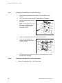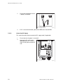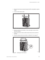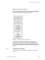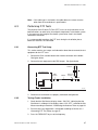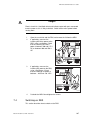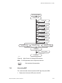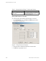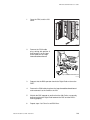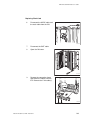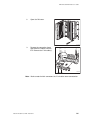
1
P012350A Ericsson GSM System RBS 2308,RBS 2309 User’s Guide EN/LZT 720 0027 R2A BINDER LABEL Uppgjord (även faktaansvarig om annan) - Prepared (also subject responsible if other) 1 (1) Nr - No. XSNFREH 4/001 59-EN/LZT 720 0027 Uen Dokansv/Godkänd - Doc respons/Approved Kontr - Checked Lena Jonsson Borg/EAB Datum - Date Rev 2004-10-21 Ericsson GSM System HEADING XXX RBS 2308 & RBS 2309 98 LZN xxx xxx R-state 65 User’s Guide EN/LZT 720 0027 R2A Cutting mark 28 38 47 54 H:\Project\Highscore\Klara dokument\R1B\RBS 2308 & 2309\2308_2309 binderlabel_portrait.doc File B Fontsize 10 Fontsize 14 Fontsize 12 Fontsize 10 EN/LZT 720 0027 R2A User’s Guide RBS 2308 & RBS 2309 Rev B Ericsson GSM System Doc nr: 2/001 59-EN/LZT 720 0027 Uen Introduction CAPTION LIST 1 Document No. EN/LZT 720 0027 RBS 2308 & RBS 2309 User’s Guide Date Rev 2004-10-21 B Personal Health and Safety Information 2 System Safety Information 3 Tools and Instruments 4 Installation of RBS 5 Antenna System Tests 6 Site Installation Tests 7 RBS Site Integration 8 Maintenance 9 Glossary 10 RBS 2308 and RBS 2309 User’s Guide E Copyright © Ericsson 2004 — All Rights Reserved Disclaimer No part of this document may be reproduced in any form without the written permission of the copyright owner. The contents of this document are subject to revision without notice due to continued progress in methodology, design and manufacturing. Ericsson shall have no liability for any error or damage of any kind resulting from the use of this document. Trademark List EN/LZT 720 0027 Uen R2A 2004-10-21 RBS 2308 and RBS 2309 User’s Guide Contents 1 Introduction 1 1.1 Product Overview 2 1.2 Target Groups 3 1.3 Installation and Integration Process Overview 4 1.4 Radio Site Implementation Process 5 1.5 RBS Library Overview 8 1.6 Release History 8 2 Personal Health and Safety Information 11 2.1 Introduction 11 2.2 Hazard Symbols and Admonitions 12 2.3 General Safety Precautions 13 2.4 Electric Shock Hazards 14 2.5 Energy Hazards 15 2.6 Fire Hazard 16 2.7 Heat Hazards 17 2.8 Mechanical Hazards 18 2.9 Radio Frequency Exposure Hazards 19 2.10 Laser Hazards 20 2.11 Chemical Hazards 21 2.12 Other Hazards 23 3 System Safety Information 27 3.1 Introduction 27 3.2 Admonitions and Safety Symbols 28 3.3 Batteries 29 3.4 Electrical Installation 30 3.5 Electrostatic Discharge 31 3.6 Equipment Handling 32 3.7 Ground Connection 33 3.8 Lightning Protection 33 4 Tools and Instruments 35 4.1 Tools for Installation of RBS 2308 and RBS 2309 35 EN/LZT 720 0027 Uen R2A 2004-10-21 RBS 2308 and RBS 2309 User’s Guide 4.2 Equipment for Antenna System Tests 36 4.3 Equipment for Site Installation Tests 37 4.4 Equipment for RBS Site Integration 37 4.5 Equipment for Maintenance 38 4.6 Kit Specifications 39 5 Installation of RBS 41 5.1 Introduction 41 5.2 Preconditions 41 5.3 Torque Settings 42 5.4 Installation Procedure 43 6 Antenna System Tests 81 6.1 Checking the Installation 83 6.2 Calibrating the Antenna Tester 84 6.3 Performing DTF Tests 87 6.4 Naming a DTF Measurement 90 6.5 Calculating the Feeder Attenuation 91 6.6 Calculating the Feeder Delay 93 6.7 Performing SWR Test 96 6.8 Naming an SWR Measurement 98 6.9 Performing Concluding Routines 99 6.10 SWR ↔ Return Loss Conversion Table 103 7 Site Installation Tests 105 7.1 Preconditions 105 7.2 Inspecting Cable Connections 106 7.3 Checking AC Mains and DC Power Supply 106 7.4 Switching on RBS 107 7.5 Testing Fan Unit 109 7.6 Setting IDB Parameters 110 7.7 Reading Fault Status 138 7.8 Testing External Alarms 139 7.9 Performing Concluding Routines 141 8 RBS Site Integration 147 8.1 Testing Transmission 148 8.2 Bringing the RBS into Service 150 8.3 Making Test Calls on the Air Interface 151 EN/LZT 720 0027 Uen R2A 2004-10-21 RBS 2308 and RBS 2309 User’s Guide 8.4 Performing Concluding Routines 156 9 Maintenance 161 9.1 Introduction 161 9.2 Preconditions 161 9.3 Fault Localisation Using OMT 162 9.4 Troubleshooting Using the RBS Indicators 179 9.5 HW Replacement 191 10 Glossary 229 EN/LZT 720 0027 Uen R2A 2004-10-21 RBS 2308 and RBS 2309 User’s Guide EN/LZT 720 0027 Uen R2A 2004-10-21 RBS 2308 and RBS 2309 User’s Guide 1 Introduction This User’s Guide consists of the chapters listed below. Each chapter is briefly summarised. Introduction This chapter. Personal Health and Safety Information Contains personal health and safety information that applies when working with Ericsson system products. System Safety Information Contains system safety information that applies when working with Ericsson system products. Tools and Instruments Contains lists of all recommended tools and instruments. Installation of RBS 2308 and RBS 2309 Describes activities for: • Installation of the mounting base • Connection of cables • Connection of external antenna • Mounting the radio cabinet on the mounting base Antenna System Tests Describes the site specific antenna tests that should be performed on site. Site Installation Tests Describes the site specific tests that should be performed on-site. EN/LZT 720 0027 Uen R2A 2004-10-21 1 RBS 2308 and RBS 2309 User’s Guide RBS Site Integration Describes how to integrate an RBS site into a network. Maintenance Describes first line Maintenance. This means that swap repair is carried out on site and that only replaceable units are handled. Glossary Contains abbreviations and acronyms used in the text. 1.1 Product Overview The RBS is a GSM EDGE micro base station for both indoor and outdoor micro cell applications. It is a small yet complete station, with transceivers, switching functions and transmission. The RBS can be mounted on a mast/pole as easily as it can be fitted to a wall. Figure 1 2 RBS Overview EN/LZT 720 0027 Uen R2A 2004-10-21 RBS 2308 and RBS 2309 User’s Guide IXU Interface and Switching Unit MBU Mounting Base Unit MCB Multicasting Box RRU Remote Radio Unit RXBP RX Bandpass Filter TIM Transmission Interface Module External optional battery backup is possible, as well as the option of having integrated antennas within the base station. 1.2 Target Groups This section describes the target group for this manual, which is all personnel involved in activities relating to the installation and integration of an RBS site. Chapters Introduction, Safety Instructions and Tools and Instruments used by all groups Cabinet Installation Antenna System Tests Site Installation Tests Installation RBS Site Integration Fault Handling OMT TEMS ON/OFF YES NO CLR 1 2 4 * 3 5 7 6 8 0 9 # Test and Integration P008221B Figure 2 Chapters Related to Specific Target Groups During the whole Radio Site Implementation (RSI) process and the product’s life cycle, the target groups require documents in addition to the above mentioned manuals to complete the work. EN/LZT 720 0027 Uen R2A 2004-10-21 3 RBS 2308 and RBS 2309 User’s Guide Qualifications for Installation Personnel Ericsson recommends that installation personnel possess the following skills: • Technical college or equivalent education with an emphasis on electrical engineering • Familiarity with the equipment used during the installation process • Knowledge of antenna systems • Appropriate training and medical certificate for working at heights • Good understanding of technical English Qualifications for Test and Integration Personnel Ericsson recommends that testing and integration personnel possess the following skills: 1.3 • Basic Ericsson RBS 2000 Operation and Maintenance knowledge. Personnel should be familiar with the tools and instruments recommended in the chapters Antenna System Tests, Site Installation Tests, and RBS Site Integration. • Basic GSM knowledge • Basic RBS 2000 knowledge • Good understanding of technical English Installation and Integration Process Overview This section describes the overall Installation and Integration process. This process covers the work that follows the Installation Engineering process: testing the antenna system, installing the cabinet, performing site installation tests, and integrating the site into the network. A process overview is shown below. 4 EN/LZT 720 0027 Uen R2A 2004-10-21 RBS 2308 and RBS 2309 User’s Guide Installation Engineering Antenna System Tests Cabinet Installation Site Installation Tests RBS Site Integration P009519B Figure 3 1.4 The Installation and Integration Process Radio Site Implementation Process This section describes the overall Radio Site Implementation process, of which the Installation and Integration process is a part. The Radio Site Implementation process covers the work from the initial stages of receiving an order, planning and designing the entire network, to installing the RBS sites and integrating them into the network. Contract is signed Network Design Site Acquisition Civil Works Radio Site Installation Engineering Installation & Integration Acceptance (of site) P007657B Figure 4 The Radio Site Implementation Process For further information about the planning process, see: EN/LZT 720 0027 Uen R2A 2004-10-21 5 RBS 2308 and RBS 2309 User’s Guide Radio Site Installation Engineering Manual EN/LZT 302 069 Network Planning Process The Network Planning process consists of the following activities: • Dimensioning of network • Dimensioning of equipment for radio, transmission, switching, operation and maintenance • Defining and ordering market adaptation products, for example programs for national signalling towards the public telephone network • Measurement of radio frequency and interference • Producing digital maps and data Site Acquisition The Site Acquisition process is performed in close cooperation with the Civil Works process and, to some extent, with the Engineering process. The Site Acquisition process consists of the following activities: • Searching for sites and obtaining a site appraisal • Outlining the site design and evaluating the cost • Negotiating and signing leasing contracts • Handling permits and arranging a handover to the Engineering personnel Civil Works The Civil Works process is performed in close cooperation with the Site Acquisition process and the Engineering process. The Civil Works process consists of the following activities: 6 • Preparing a detailed civil works design of the site • Updating the costs for the site construction • Arranging the site construction • Performing a site inspection and handing over an as-built document to the Engineering personnel EN/LZT 720 0027 Uen R2A 2004-10-21 RBS 2308 and RBS 2309 User’s Guide Engineering The Engineering process begins when the Site Acquisition and Civil Works processes are complete. The Engineering process consists of the following activities: • Measuring and collecting information about sites • Designing the antenna and radio configuration, and producing cable drawings • Making drawings showing the positions of the antenna and RBS equipment • Defining areas of responsibility between the purchaser and the contractor • Producing site-specific information in the Site Installation Documentation. For more information about the results from the site engineering process, see: Radio Site Installation Engineering Manual EN/LZT 302 069 Installation and Integration The work involved in this process is performed by installation personnel, and test and integration personnel. Installation personnel are responsible for the following activities: • Installing the antenna system • Installing the RBS • Earthing the RBS • Connecting a power supply to the RBS • Connecting the antenna system to the RBS • Installing cable ladders and cable ducts • Installing battery backup • Installing PCM cables The test and integration personnel are responsible for the following activities: • Performing the tests specified in the contract and integrating the site • Troubleshooting if tests indicate a fault EN/LZT 720 0027 Uen R2A 2004-10-21 7 RBS 2308 and RBS 2309 User’s Guide • 1.5 Recording the test results in the Site Installation Documentation, which is returned to the engineering personnel RBS Library Overview For information on the RBS library and other manuals related to the RBS, see: RBS 2000 Library Overview 1.6 LZN 302 73 Release History Except for editorial changes, such as the correction of spelling, grammar, and layout, this manual has been revised as follows: 1.6.1 R1A to R2A RBS 2309 Information about RBS 2309 has been added to the document. Personal Health and Safety Information New safety chapter. System Safety Information New safety chapter. Installation of RBS 2308 8 • Section Tightening Torques added • Section Installing the MBU on a Wall updated with a figure that shows connection of site earthing to the MBU • Section Installing the IXU (Master RBS Only) updated with a new figure for earthing of outer shield only • Updated figure for strapping cables using the appropriate cable tie anchor • Updated figure for installation of the top sunshield EN/LZT 720 0027 Uen R2A 2004-10-21 RBS 2308 and RBS 2309 User’s Guide Antenna System Tests • Section Calculating Feeder Delay added Site Installation Tests • Updated figure for RRU and IXU interface panels • Section Connecting OMT updated with text explaining what to do if an extended OMT cable is connected • Section Defining Transmission Interface E1, 120 about ports C and D as a multidrop pair • Section Reading Fault Status updated with information about what is displayed when an MO fault is selected • Test record for Stand-alone updated with a check for external alarms updated with information RBS 2308 Maintenance • Updated figures for RRU and IXU interface panels • Torque value added for mounting of the TIM • Updated figure for disconnecting the power cable from the RRU • New figure for removal of the fan unit Appendix: Fault List Micro New fault list including all alarms related to all micro cabinets. 1.6.2 R1A This is the first release of this manual. EN/LZT 720 0027 Uen R2A 2004-10-21 9 RBS 2308 and RBS 2309 User’s Guide 10 EN/LZT 720 0027 Uen R2A 2004-10-21 RBS 2308 and RBS 2309 User’s Guide 2 Personal Health and Safety Information 2.1 Introduction This document presents the personal health and safety information that applies when working with Ericsson system products. The instructions included are mandatory to ensure personal safety while working with Ericsson system products. Note: Reduce the risk of accidents by studying all the information carefully before starting work. If questions arise regarding health and safety information, contact the supervisor or the local Ericsson company for clarification. For information on product safety for Ericsson system products, see: System Safety Information, Ericsson System Products 124 46–2886 Local Regulations Local regulations, first and foremost national regulations, override the information in this document. Where applicable local regulations are not available, the information herein prevails. Product Exclusion Indication The information in this document covers personal health and safety aspects of all Ericsson system products. As all the information does not apply to a specific product, the readers must familiarize themselves with the potential hazards indicated on the product they are working with to understand which document parts apply to their product. 2.1.1 Target Group The target group for this health and safety information is personnel who work with Ericsson products. All personnel who work with engineering, installation, test, and operation and maintenance of Ericsson products must familiarize themselves with this information. 2.1.2 Educational Requirements The safety instructions in the relevant manuals or documents require that persons performing work on Ericsson products have the necessary education, EN/LZT 720 0027 Uen R2A 2004-10-21 11 RBS 2308 and RBS 2309 User’s Guide training and competence required to perform work correctly. For certain work, additional or special training may be required, for example authorization for Authorized Service Providers (ASP). ASP is an Ericsson certification procedure. A good understanding of technical English is required, or of the language that the information is presented in, to ensure that these and other instructions can be understood and complied with. 2.2 Hazard Symbols and Admonitions This section presents the types of admonitions and hazard symbols used in all Ericsson documentation. There are three levels of personal health and safety admonitions that indicate risk to persons: danger, warning and caution. Hazard symbols are used to indicate these and to present various other hazards. The admonition levels for personal health and safety are presented in order of severity, with danger being the highest level, warning the intermediary and caution the lowest. When admonitions are encountered anywhere in a document, the information included should be read and any instructions should be followed. 2.2.1 Personal Health and Safety Admonitions Personal health and safety admonitions are used to indicate hazardous activities and are normally preceded by the common hazard symbol shown in the figure below, or in specific cases by specialized symbols, see Section 2.2.2 Special Hazard Symbols on page 13. P002643A Figure 5 Safety Hazard Symbol The hazard symbol is common for all three admonition levels. The three admonition levels are defined below: Danger! Indicates that there is an imminent hazard that is likely to result in death or serious injury. Note: 12 Danger can be accompanied by other symbols depending on the country of operation. Warning! Indicates that there is a potential hazard that could result in death or injury. Caution! Indicates a hazard that could result in minor or moderate injury. EN/LZT 720 0027 Uen R2A 2004-10-21 RBS 2308 and RBS 2309 User’s Guide 2.2.2 Special Hazard Symbols This section presents special hazard symbols used to indicate the risk of chemical, electric shock, fire, heat, laser and Radio Frequency (RF) exposure hazards: P010387A Figure 6 Chemical Hazard Symbol P002645A Figure 7 Electrical Hazard Symbol P010385A Figure 8 Fire Hazard Symbol P010274A Figure 9 Heat Hazard Symbol P010341A Figure 10 Laser Hazard Symbol P002644A Figure 11 2.3 RF Exposure Hazard Symbol General Safety Precautions This section presents general safety precautions to ensure that persons are not injured when working with equipment. • Items of jewelry, for example rings, watches and necklaces should be removed as they can catch on moving parts, or when lifting equipment. • Pay attention to the hazard labels and other information labels on products. EN/LZT 720 0027 Uen R2A 2004-10-21 13 RBS 2308 and RBS 2309 User’s Guide 2.4 • Never remove or cover hazard symbols as this can endanger persons working with the product. • Only use the tools described, in the manner indicated, in instructions. Electric Shock Hazards This section provides information and instructions relating to equipment operating on voltage that entails an electric shock hazard. Note: This information only applies to products marked with the electric shock hazard symbol. The term Electric Shock Hazard is defined below: Electric Shock Hazard Hazard at voltage equal to or above 42.4 V peak or 60 V DC. Danger! Electric shock risk. Avoid both direct and indirect contact with parts connected to mains power as this is likely to be fatal. Switch off the mains power before starting work. Danger! Improper electrical installation may cause fire or electric shock that is likely to be fatal. Only a qualified and authorized electrician is permitted to install or modify electrical installations. 2.4.1 Note: Only qualified electricians are allowed to work directly with equipment that presents an electric shock hazard. Note: AC mains installation must be carried out according to local regulations. Safety Precautions for Working with Electrical Equipment The following precautions must be observed when working with electrical equipment: • 14 The AC mains is switched off. EN/LZT 720 0027 Uen R2A 2004-10-21 RBS 2308 and RBS 2309 User’s Guide 2.5 • Equipment exposed to moisture is protected with a tent or other equipment. • Power cables are installed according to instructions. • Installed cables are always clearly marked with labels. • All personnel are familiar with and understand the warning signs on equipment. • Only tested electrical tools are used. • Holes are never drilled in equipment, or walls, without ensuring that there are no concealed cables. Energy Hazards This section provides information on how to avoid energy hazards. The term energy hazard is defined below: Energy Hazard 2.5.1 Hazard at a stored energy level of 20 J or an available continuous power level of 240 VA. Batteries This section provides instructions and information on the proper handling of batteries. Note: Where Ericsson is not the supplier of battery equipment, see the manufacturer’s information on battery safety. Caution! Improper handling of batteries can result in the batteries short-circuiting, which can result in serious injury due to high energy levels. Exercise the necessary care when working with batteries. EN/LZT 720 0027 Uen R2A 2004-10-21 15 RBS 2308 and RBS 2309 User’s Guide Lithium Batteries Warning! Switching poles when replacing lithium batteries can result in an explosion that can lead to injury. Always ensure that lithium batteries are connected to the right poles. 2.5.2 Capacitors and Uninterruptible Power Systems This section provides information on how to avoid energy hazards in Capacitors and Uninterruptible Power Systems (UPS). Warning! High energy levels are present in this unit. Improper handling of the unit can lead to short circuiting that can result in serious injury. Exercise care when working with this unit. Note: 2.5.3 Some capacitors and UPSs have energy levels above 240 VA. If this is the case this is indicated on the product with a voltage hazard. Safety Precautions for Avoiding Energy Hazards The following precautions must be observed when working with batteries and other units that present an energy hazard: 2.6 • All metallic objects worn, such as wrist watches, rings, bracelets, and so on are removed. • Disconnect the charger power supply until the work is complete. • Only use insulated tools. Fire Hazard This section provides instructions and information on safety precautions for preventing fire. 16 EN/LZT 720 0027 Uen R2A 2004-10-21 RBS 2308 and RBS 2309 User’s Guide Warning! In the event of a fire, evacuate the building or equipment site and raise the fire alarm at the closest alarm point, or call the emergency number. Do not re-enter a burning building under any circumstances. Warning! Heater in operation. Do not block the heater vents or place combustible materials close to the unit, as this can cause a fire that can endanger life. 2.6.1 Fire Precautions Note: When working with the installation or maintenance of equipment that involves interfering with the fire sectioning of a building, this should be carried out as quickly as possible. Fire can spread to neighboring rooms. When working on equipment cable ducts, channels and access holes might have to be opened, thereby interfering with the fire sectioning of the building. The instructions below have to be followed when work has been completed to restore the building’s fire sectioning: 1. Close the cable ducts and fire doors (if applicable) as soon as possible. 2. Seal cable ducts according to the regulations for the building. 3. Minimize the amount of inflammable material. 4. Remove empty packaging material from the equipment site. 5. Check that there is a functioning powder or carbon dioxide fire extinguisher for electric apparatus at the equipment site. 2.7 Heat Hazards This section describes how to avoid injury from hot surfaces or hot air in equipment. EN/LZT 720 0027 Uen R2A 2004-10-21 17 RBS 2308 and RBS 2309 User’s Guide Caution! Parts inside this equipment attain high temperatures during normal operation, which can cause burns to the skin if touched without heat protective clothing. Always use heat protective clothing when working with equipment containing hot surfaces, or switch the equipment off and allow it to cool before starting work. Caution! A heater, producing hot air, is in use in this equipment. Direct contact with hot air can lead to burns. When the heater is in operation, avoid close contact with the heater air evacuation vent. 2.8 Mechanical Hazards This section provides information on mechanical hazards in equipment containing sharp edges or rotating blades. Caution! Sharp metal edges may exist that can cause cuts to the skin or clothing. Wear protective gloves when handling this equipment. Caution! Rotating fan blades can cause injury to body parts that come into contact with the blades. Blades in fan units continue to rotate for a period of time, even after the fan has been switched off. Wait until fans have stopped rotating completely before starting work on or near fans. 18 EN/LZT 720 0027 Uen R2A 2004-10-21 RBS 2308 and RBS 2309 User’s Guide 2.9 Radio Frequency Exposure Hazards This section provides instructions and information on potential hazards related to radio frequency (RF) electromagnetic field (EMF) exposure from fixed radio transmitters (as opposed to mobile phones). 2.9.1 General RF Safety Information Caution! Excessive RF exposure can result in potentially adverse health effects. If it is suspected that RF exposure limits may be exceeded, ensure that transmitting antennas are switched off, or reduce output power whilst working with, or near, antennas. Note: 2.9.2 RF exposure limits are specified by national and international health authorities in standards, regulations or guidelines. The limits include wide safety margins to protect from potentially harmful tissue heating. RF Safety for Installation and Maintenance Personnel It is important that all personnel working with the installation and maintenance of transmitting equipment and antennas have basic knowledge regarding RF safety. They must have been informed or trained to be observant of potential risks of RF exposure exceeding specified safety limits, and be aware of precautionary measures necessary for differing situations. Caution! Do not stand or work in front of an operational antenna, unless it has been verified or documented that RF exposure levels are within specified safety limits. EN/LZT 720 0027 Uen R2A 2004-10-21 19 RBS 2308 and RBS 2309 User’s Guide Caution! Always be aware of other RF transmission antennas located close to the antenna you will be working with. If the RF exposure level is unknown, contact the equipment operator or ensure that measurements are done to verify that levels are below specified safety limits before starting work. Caution! Broken or disconnected RF cables can lead to exposure levels reaching, or exceeding, specified safety limits. Repair or reconnect cables before starting work. Note: 2.10 Working outside of the main transmission direction of ordinarily configured antennas is in most situations possible, since the RF exposure does not normally reach specified safety limits in these directions. Laser Hazards This section provides information on working with products that have devices that communicate through optical fibres using laser. Note: 2.10.1 This information only applies to products marked with the laser hazard symbol, stating the class of laser in use. Class 1 Laser This section provides information on working with equipment containing Class 1 laser. Products containing a Class 1 laser, according to IEC/EN 60825, are safe to use and therefore have no requirements for cautions or warnings during operation or maintenance procedures. 2.10.2 Class 3 Laser This section provides information on working with equipment containing Class 3 laser. 20 EN/LZT 720 0027 Uen R2A 2004-10-21 RBS 2308 and RBS 2309 User’s Guide Danger! Never look directly into the end of a fiber optic cable, or other laser source. Equipment that transmits laser light can cause permanent eye damage. Switch off the laser before starting work on laser equipment. Safety Precautions for Working with Class 3 Laser The following precautions must be observed when working with products containing a Class 3 laser hazard symbol: 2.11 • Never look into the light emitting end of a functioning optical fibre. • Switch off units producing the laser signal before disconnecting an optical fibre. Chemical Hazards This section provides information on chemical hazards that can be present in products. 2.11.1 Beryllium Oxide Hazard This section provides information on Beryllium Oxide (BeO). BeO is a restricted substance that is contained in certain components in some Ericsson products. If a product contains BeO, this is clearly marked on the unit containing BeO. The BeO hazard symbol is shown in the figure below. P010382A Figure 12 Note: BeO Hazard Symbol This information only applies to products marked with the BeO symbol. EN/LZT 720 0027 Uen R2A 2004-10-21 21 RBS 2308 and RBS 2309 User’s Guide Danger! This product contains Beryllium Oxide (BeO), which can cause injury to skin or mucous membranes severe enough to endanger life or cause permanent injury. BeO dust is created by chafing, filing, or breakage and is extremely dangerous if inhaled, even for only a few seconds. Particles penetrating the skin through wounds or abrasions are liable to cause chronic ulcerations. Do not handle components containing BeO without protection. Symptoms of BeO Poisoning Symptoms of BeO poisoning are respiratory distress, cyanosis (grey-blue discoloration of the skin and mucous membranes), or both. These symptoms may develop within a week, or after a period of several years. Safety Precautions for Working with Components Containing BeO The following precautions must be observed when working with components containing BeO: 2.11.2 • Do not carry loose components in pockets, bags, or containers, or tamper with them in any way that could cause breakage or disintegration. • Do not apply excessive heat during soldering. • Do not break open components for inspection. • Store components in their original packaging and do not mix them with other components. • Ensure that components do not become mechanically damaged. • Use care when replacing defective components. • Do not blow on exposed surfaces due to the danger of BeO dust. • In case of accident, or if you feel unwell, seek medical advice immediately and show the label where possible. Battery Acid Hazard This section provides information on chemical hazards related to lead-acid batteries. 22 EN/LZT 720 0027 Uen R2A 2004-10-21 RBS 2308 and RBS 2309 User’s Guide Caution! Excessive heat can cause battery casing to soften and warp, potentially allowing acid to escape. In contact with the skin, acid can cause injury, and if breathed in, can affect the airways. Use protective equipment when replacing batteries. Caution! Batteries can leak electrolyte if improperly handled. Electrolyte in contact with skin or eyes can cause injury. In the event of electrolyte injuries, rinse the affected area with water and seek medical attention immediately. Use protective equipment when replacing batteries. Safety Precautions for Working with Lead-acid Batteries The following precautions must be observed when working with lead-acid batteries: • 2.11.3 Eye wash facilities, and protective gloves or aprons are available. Gas Explosion Hazard Open-cell lead acid batteries can give off gases that in the event of a fire can cause an explosion that is likely to be fatal. All battery areas must be adequately ventilated and protected from fire. Danger! Do not use open-cell lead acid batteries. Open-cell lead acid batteries give off hazardous gases that, if ignited, can cause an explosion that is likely to be fatal. 2.12 Other Hazards This section includes safety instructions and rules for the following hazards: • Handling Heavy Goods EN/LZT 720 0027 Uen R2A 2004-10-21 23 RBS 2308 and RBS 2309 User’s Guide • 2.12.1 Working at Height Handling Heavy Goods This section provides instructions and rules for handling heavy goods. Note: Follow local regulations for safety clothing and safety equipment for hoisting and moving goods. Falling Objects Warning! Risk for falling objects, work at height in progress. Falling objects can cause serious injury or even be fatal. Always wear a helmet and avoid standing in the danger area. Overloading Warning! Overloading, or other wrong use of lifting devices, can cause serious injury to anyone hit by falling equipment. Do not create an angle exceeding 90 between lifting straps as this increases the strain on them and can cause them to snap. Caution! The equipment is heavy. Lifting the equipment without the aid of a lifting device can cause injury. 24 EN/LZT 720 0027 Uen R2A 2004-10-21 RBS 2308 and RBS 2309 User’s Guide Unsecured Equipment Caution! Tip risk! Unsecured equipment can tip over if not secured properly, causing injury to personnel. Secure products with a high center of gravity as soon as possible to avoid accidents. 2.12.2 Working at Height This section provides information about working at height. For information on climbing instructions for working at height, see: Safe Climbing LZY 213 715/02 Safety Precautions for Working at Height The following precautions must be observed when working at height: • Personnel have the appropriate training and medical certificate. • A full-body safety harness and safety helmet are available. • Adequate protective clothing, essential in cold and wet weather, is available. • All lifting devices are tested and approved, and ready for use. • All personnel in the area are wearing helmets. EN/LZT 720 0027 Uen R2A 2004-10-21 25 RBS 2308 and RBS 2309 User’s Guide 26 EN/LZT 720 0027 Uen R2A 2004-10-21 RBS 2308 and RBS 2309 User’s Guide 3 System Safety Information 3.1 Introduction This document presents the system used for presenting system safety information for Ericsson products. The instructions included are mandatory to ensure product safety while working with Ericsson products. Local regulations must be taken into consideration. The system safety information in this document is in addition to local regulations. Note: Reduce the risk of accidents by studying all the instructions carefully before starting work. If questions arise regarding the safety instructions, contact the supervisor or the local Ericsson company for clarification. For information on personal health and safety for Ericsson system products, see: Personal Health and Safety Information, Ericsson System Products 124 46–2885 Local Regulations Local regulations, first and foremost national regulations, override the information in this document. Where applicable local regulations are not available, the information herein prevails. Product Exclusion Indication The information in this document covers system safety information for all Ericsson system products. As all the information does not apply to a specific product, the readers must familiarize themselves with the potential hazards indicated on the product they are working with to understand which document parts apply to their product. 3.1.1 Target Group The target group for this system safety information is personnel who work with Ericsson products. All personnel who work with engineering, installation, test, and operation and maintenance of Ericsson products must familiarize themselves with this information. EN/LZT 720 0027 Uen R2A 2004-10-21 27 RBS 2308 and RBS 2309 User’s Guide 3.1.2 Educational Requirements The product safety instructions in the relevant manuals or documents require that persons performing work on Ericsson products have the necessary education, training and competence required to perform work correctly. For certain work, additional or special training may be required, for example authorization for Authorized Service Providers (ASP). ASP is an Ericsson certification procedure. A good understanding of technical English is required, or of the language that the information is presented in, to ensure that these instructions can be understood and complied with. 3.2 Admonitions and Safety Symbols This section presents the types of admonitions and safety symbols used in all documents for Ericsson system products. There are two types of system safety admonitions that indicate risk to products: Do! and Stop!. When admonitions are encountered anywhere in a document, the information included should be read and any instructions should be followed. The figures below show the symbols used to indicate product safety admonitions: Figure 13 Do Safety Symbol Figure 14 Stop Safety Symbol The terms Do! and Stop! are defined below: Do! Indicates an action that must be performed to prevent equipment damage, software corruption, data loss or service interruption. Stop! Indicates that action must be avoided to protect equipment, software, data or service. The term ‘‘Note’’ is used to present important information that might otherwise be overlooked. 3.2.1 Special Hazard Symbols This section presents special hazard symbols used to indicate the risk of Electrostatic Discharge (ESD): 28 EN/LZT 720 0027 Uen R2A 2004-10-21 RBS 2308 and RBS 2309 User’s Guide P002646A Figure 15 3.3 Electrostatic Discharge Hazard Symbol Batteries This section provides information on damage that can be caused to products containing batteries that are damaged. 3.3.1 Overheated Batteries Caution! Do! Check batteries for signs of overheating. The casing surrounding overheated batteries can be soft and warped. Replace damaged batteries according to instructions. If it is suspected that batteries are overheated, check the following: • The internal temperature of the equipment is below +60 C (140 F). • Batteries have not leaked. Corrective Actions 1. Replace overheated batteries. 2. Treat leakages from batteries as described in Section 3.3.2 Treating Hazardous Waste from Leaks on page 29. 3.3.2 Treating Hazardous Waste from Leaks Caution! Do! Check batteries for acid leakage. Acid can corrode the product. Replace leaking batteries according to instructions. EN/LZT 720 0027 Uen R2A 2004-10-21 29 RBS 2308 and RBS 2309 User’s Guide In case of spillage of hazardous substances, there should always be sufficient absorbers or neutralizing materials available on site. There is a danger of spillage occurring when installing, removing, replacing or servicing batteries. The absorbers and neutralizing materials must be suitable for the hazardous substances involved. Typical neutralizing agents are shown inTable 1 on page 30. Table 1 Typical Neutralizers Chemical Compound Baking soda (bicarbonate) NaHCO3 Sal soda Na2CO3IOH2O Soda ash Na2CO3 Note: 3.4 Typical Neutralizers Absorbers and neutralizing products will vary, depending on the country and battery manufacturer. Consult the battery manufacturer for specific details of absorbers and neutralizing materials. Electrical Installation This section provides information on ensuring that AC and DC powered products are not damaged due to improper installation. Caution! Stop! Do not install or modify AC or DC powered equipment unless you are a qualified and authorized electrician. Improper installation work can seriously damage the equipment. 3.4.1 Safety Precautions for Working with Electrical Installations The following precautions must be observed when working with electrical installations: 1. Ensure that approved circuit breakers or fuses are installed. 2. Ensure that the cables used have a sufficient cross-sectional area in accordance with product requirements and local laws and regulations. 3. Ensure that conductors are connected according to the connection diagram. 4. Label the cables correctly. 5. Check the installation work upon completion. 30 EN/LZT 720 0027 Uen R2A 2004-10-21 RBS 2308 and RBS 2309 User’s Guide 3.5 Electrostatic Discharge This section provides information and instructions on Electrostatic Discharge (ESD) product safety. ESD is defined below. A static electric charge accumulates when a body rubs against clothes, slides against a chair, when shoes rub against a floor, or when ordinary plastics are handled, and so on. The electrostatic charge can remain for a considerable length of time and is discharged when the body comes into contact with conductive material. ESD An ESD wrist strap must be used when working with ESD sensitive components, even in equipment rooms fitted with ESD protective floor covering. Although ESD floor covering reduces the risk of ESD, if the wrong type of shoes are used, or if the person is already charged when they enter the room, the floor covering in itself does not protect from this, and therefore an ESD wrist strap must be used. 01_0250A Figure 16 ESD wrist strap The ESD wrist strap contains a resistor with resistance greater than 1 M in the cable to protect the operator. The resistance value is low enough to discharge the electrostatic voltage. The ESD wrist strap must be connected to ground. Instructions for ESD Wrist Strap Use 1. Place the ESD wrist strap around your wrist and insert the connector at the other end to the ground (earth) terminal on the equipment. 2. Always use the wrist strap when and where its use is required. Note: Test the ESD wrist strap regularly. EN/LZT 720 0027 Uen R2A 2004-10-21 31 RBS 2308 and RBS 2309 User’s Guide 3.5.1 Handling Printed Board Assemblies and IC Components Note: Treating all components as if they are ESD sensitive, whether they have IC components or not, reduces the risk for ESD and significantly reduces the operating time between failure. Caution! Stop! This product contains components sensitive to ESD. Use an approved ESD wrist strap, connected to the product grounding point, to avoid damaging these components. Caution! Do! Always use an approved ESD wrist strap when working with sensitive equipment. Damage to components mounted on printed board assemblies can occur if an ESD wrist strap is not used. 3.5.2 Storing and Transporting Printed Board Assemblies and IC Components When storing or transporting printed board assemblies or IC components, ensure one of the following: 3.6 • The item is stored or transported in its original packaging, or in other anti-ESD material. • The item is stored or transported in a conductive material, or a special IC carrier that either short-circuits or insulates all leads of the components. Equipment Handling This section provides information on how to avoid damage to products when handling them. 32 EN/LZT 720 0027 Uen R2A 2004-10-21 RBS 2308 and RBS 2309 User’s Guide Caution! Do! Tip risk! This equipment has a high center of gravity without all units installed. Secure the equipment before opening the door. Caution! Stop! Never lift a unit by the cables as this can damage the equipment. 3.7 Ground Connection This section provides information on product grounding (earthing) safety. Note: The terms “grounding” and “earthing” are synonyms. Caution! Do! Products not connected to ground risk being damaged by overvoltage or overcurrent. Always connect products to ground according to instructions. 3.8 Lightning Protection This section provides information on protecting products from damage due to lightning where a lightning protection system is available. Caution! Do! Connect products to the lightning protection system to protect the equipment from transient surges. EN/LZT 720 0027 Uen R2A 2004-10-21 33 RBS 2308 and RBS 2309 User’s Guide 34 EN/LZT 720 0027 Uen R2A 2004-10-21 RBS 2308 and RBS 2309 User’s Guide 4 Tools and Instruments This section contains lists of all tools and instruments recommended for the complete installation of the RBS 2308 and RBS 2309. 4.1 Tools for Installation of RBS 2308 and RBS 2309 Table 2 Basic Tools for Installation Description Specification Adjustable spanner 10" - Drilling machine - Knife (1) - Measuring tape (1) 6m - Pen Screwdrivers (1) Torx: T20 and T30 Screwdrivers Side cutting pliers Snip nose pliers 3 mm and 5.5 mm (1) - (1) 10 – 19 mm (1) - Socket set Spirit level Torque wrench U wrenches (1) (1) Wire stripper 5 – 25 Nm 13 mm, 16 mm, 17 mm, 20 mm and 22 mm 0.2 – 6 mm2 (1) Included in Personal Tool Set, Product Number LTT 601 135/1. Table 3 4.1.1 Special Tools for Installation Description Specification Product Number Crimping tool set for grounding LTT 601 86 Torque wrench for N connector LSS 103 25/1 Torque wrench for TNC connector LTT 601 93 Documentation The following documents are required for the installation procedure: EN/LZT 720 0027 Uen R2A 2004-10-21 35 RBS 2308 and RBS 2309 User’s Guide • Completed and approved record prepared during site preparation • Site Installation Documentation (prepared by the Installation Engineering department) Standard Site Material Installation Instructions 4.2 EN/LZT 720 0014 Equipment for Antenna System Tests Table 4 Test Equipment for Antenna System Tests Description Specification Product Number Antenna Tester Set Anritsu Site Master S331C LPK 102 101/8 The Anritsu Site Master S331C is recommended for the Antenna System Tests, but the following Site Master models can still be used if available: S251A/B and S331A/B for GSM 800/900/1800/1900 antenna systems. 4.2.1 Documentation The following documents are required for the antenna system tests: • Site Installation Documentation • A test record For more detailed information on the Anritsu Site Master, see: Anritsu Site Master User’s Guide (included in Antenna Tester Set) Note: Instructions for Site Master models S251A/B and S331A/B for GSM 800/900/1800/1900 antenna systems are not included in this document. When using any of these models ensure that all necessary accessories are included. See: Standard Tools and Equipment Catalogue 36 LZT 720 0013 EN/LZT 720 0027 Uen R2A 2004-10-21 RBS 2308 and RBS 2309 User’s Guide 4.3 Equipment for Site Installation Tests Table 5 Test Equipment for Site Installation Tests Description Specification Product Number Fluke 79 III Multimeter LPK 102 024/3 OMT Kit OMT Kit and SW cable NTM 201 2289/15 Torx screwdriver - Torx T20 (1) (1) Included in Personal Tool Set, product number LTT 601 135/1. 4.3.1 Documentation The following documents are required for the site installation tests: • A completed test record from antenna system tests • A test record for site installation tests OMT User’s Manual (included in OMT Kit ) 4.4 Equipment for RBS Site Integration Table 6 4.4.1 EN/LZN 720 0001 Test Equipment for RBS Site Integration Description Specification Product Number Loop forward/ backward board Transmission test board LPY 107 757/1 TEMS Kit GSM 800/1900 FAB 801 2524 TEMS Kit GSM 900/1800/1900 FAB 801 2523 Documentation The following document is required for the RBS site integration: TEMS Investigation GSM Manual (included in TEMS Kit) EN/LZT 720 0027 Uen R2A 2004-10-21 LZT 108 2684 37 RBS 2308 and RBS 2309 User’s Guide 4.5 Equipment for Maintenance Table 7 Basic Tools for Maintenance Description Specification Adjustable spanner 10" - Knife (1) - Screwdrivers (1) Torx: T20 and T30 Screwdrivers 3 mm and 5.5 mm (1) Side cutting pliers - Snip nose pliers - Socket set (1) - Torque wrench U wrenches (1) 5-25 Nm (1) Wire stripper 13 mm, 16 mm and 17 mm, 20 mm and 22 mm (1) 0.2-6 mm2 (1) Included in Personal Tool Kit, product number LTT 601 135/1. Table 8 4.5.1 Special Tools for Maintenance Description Specification Product Number Fluke 79 III Multimeter LPK 102 024/3 OMT Kit - NTM 201 2289/15 Torque wrench for N connectors LSS 103 25/1 Torque wrench for TNC connectors LTT 601 93 Documentation The following documents are required for the maintenance work: 38 OMT User’s Manual (included in OMT Kit) EN/LZN 720 0001 RBS 2308, RBS 2309, RBS 2109 and EBB-06 Hardware Reference Manual EN/LZT 720 0058 EN/LZT 720 0027 Uen R2A 2004-10-21 RBS 2308 and RBS 2309 User’s Guide 4.6 Kit Specifications For a specification of all required kits, see: Standard Tools and Equipment Catalogue EN/LZT 720 0027 Uen R2A 2004-10-21 EN/LZT 720 0013 39 RBS 2308 and RBS 2309 User’s Guide 40 EN/LZT 720 0027 Uen R2A 2004-10-21 RBS 2308 and RBS 2309 User’s Guide 5 Installation of RBS 5.1 Introduction This document describes how to install the RBS 2308 and RBS 2309. Target Group The target group for this instruction is personnel involved in the installation of an RBS. 5.2 Preconditions This section provides preconditions that must be met before starting the installation work. Note: Specific preconditions exist for wall and pole mounting. Documentation This section presents additional documents required for the installation procedure. Ensure that the following documents are available: • Completed and approved record prepared during site preparation • Site Installation Documentation (prepared by the Installation Engineering department) Standard Site Material Installation Instructions EN/LZT 720 0014 General Preconditions Before starting site work, ensure the following: • Site access permission received • Ordered RBS, equipment, specified tools and other necessary facilities have been delivered • Site power is available • Site Grounding Point is available EN/LZT 720 0027 Uen R2A 2004-10-21 41 RBS 2308 and RBS 2309 User’s Guide Note: The terms earthing and grounding are synonymous. • Transmission line from the BSC is available • During outdoor installation, protection for the RBS is available in case of bad weather Note: After installation, if the surrounding temperature changes between hot and cold, then to avoid humidity damage the RBS must not be left without power for more than 48 hours. To switch on the RBS, see Chapter Site Installation Tests: If any of the above preconditions cannot be complied with, then contact the site supervisor or person responsible for the activity that has been missed. Additional Preconditions for Wall-Mounted RBS Before installing the RBS on a wall, ensure that the following preconditions are met: • The type of fasteners are suitable for the kind of wall material on which the RBS is to be mounted • The contact surfaces on the Mounting Base Unit (MBU) are supported by the wall. If not, then a wall bracket is required If any of the above preconditions cannot be complied with, then contact the site supervisor or person responsible for activity that has been missed. Additional Preconditions for Pole-Mounted RBS Before installing the RBS on a pole, ensure that the following preconditions are met: • The pole must have the required diameter 60 – 114 mm • A wall bracket is available • A mast fixture set is available If any of the above preconditions cannot be complied with, then contact the site supervisor or person responsible for activity that has been missed. 5.3 Torque Settings This section presents the recommended torque values to be used when installing the RBS. The tools needed for the installation are found in Chapter Tools and Instruments. 42 EN/LZT 720 0027 Uen R2A 2004-10-21 RBS 2308 and RBS 2309 User’s Guide Table 9 Recommended Torque Dimension Torque Notes Ncm Nm lbf-in lbf-ft M3 110 +/- 7 - 9.7 +/- 0.6 - - M3 80 +/- 7 - 7.1 +/- 0.6 - Reduced torque for plastic covers M4 260+/- 15 - 23.1 +/1.3 - - M4 170 +/- 15 - 15.1 +/1.3 - Reduced torque for captive screws M6 - 8.8 +/- 0.5 - 6.5 +/- 0.4 - M8 - 21 +/- 1.3 - 15.5 +/- 1 - M10 - 41 +/- 2.5 - 30.2 +/1.8 - 5.4 Installation Procedure This section describes the installation procedure for the RBS. EN/LZT 720 0027 Uen R2A 2004-10-21 43 RBS 2308 and RBS 2309 User’s Guide Unpacking the RBS Installing the Wall Bracket Installing the MBU Connecting Power Replacing the Flash Card Installing the IXU (Master RBS only) Installing the RRU Connecting Earth Cables Installing the Fan Unit Installing RXBP Installing the MCB Installing the Integral Omni Antenna Installing the Integral Sector Antenna Connecting RBS Antenna Cables Testing the Installation Installing the Sunshield Performing Concluding Routines P011355D Figure 17 44 The RBS Installation Process EN/LZT 720 0027 Uen R2A 2004-10-21 RBS 2308 and RBS 2309 User’s Guide 5.4.1 Unpacking RBS Unpack the RBS on-site. To avoid damage, the RBS should not be unpacked elsewhere and then transported to site. Caution! Stop! This product contains components sensitive to ESD. Use an approved ESD wrist strap, connected to the product grounding point, to avoid damaging these components. In order to avoid damage to components due to electrostatic discharges during unpacking, personnel must not come in contact with the connectors of the RBS. Ensure that the correct material has been delivered. If the material is damaged, complain immediately to the supervisor or the transport company. 5.4.2 Installing the Wall Bracket Note: This section is only applicable for walls with very rough surfaces or when the RBS is to be mounted on a pole. This section describes how to install the wall bracket. The wall bracket is for use as a complement to the mounting interface of the Mounting Base Unit (MBU). Typical applications are rough surfaces and other conditions where the mounting interface for the MBU is not flat. The plate must also be used if the RBS is to be installed on a pole. See applicable section below. EN/LZT 720 0027 Uen R2A 2004-10-21 45 RBS 2308 and RBS 2309 User’s Guide 5.4.2.1 Installing the Wall Bracket on a Wall (Alternative) 1 Place the drilling template in the position where the RBS is to be located. 2 Use a spirit level to check that the drilling template is horizontal. 3 Mark the position of the holes to be drilled. UP Note: The wall bracket must not be used as a drilling template, to avoid damaging the rust protection surface. DRILL TEMPLATE FOR WAL L BRACKET Recomend Alternate ed holes holes P010150B 4 Remove the template and drill the holes for the fasteners. 5 Install the wall bracket and secure it in position with all the screws provided. UP P010151A 6 5.4.2.2 Loosen the four nuts, on which the MBU is to be hung, until only a few threads remain exposed. Installing the Wall Bracket on a Pole (Alternative) 1. Choose the appropriate holes. See Figure below. 46 EN/LZT 720 0027 Uen R2A 2004-10-21 RBS 2308 and RBS 2309 User’s Guide A A B UP B B A P010152A Figure 18 Installation Alternatives A Holes used for vertical poles B Holes used for horizontal poles 2. Ensure that the washers are mounted correctly and attach the two clamps with the screws and washers. See Figure below. Note: Ensure that the recess is attached in the correct direction. UP Recess P010171A Figure 19 Fastening Clamps to the Wall Bracket 3. Position the wall bracket on the pole and mount the clamps, tightening the screws alternately to avoid bending them. Ensure that the washers are mounted correctly. EN/LZT 720 0027 Uen R2A 2004-10-21 47 RBS 2308 and RBS 2309 User’s Guide Recess P010170B Figure 20 5.4.3 Installing the Wall Bracket on the Pole Installing the MBU This section describes how to install the Mounting Base Unit (MBU) on a wall or wall bracket. 5.4.3.1 Installing the MBU on a Wall 1 Place the drilling template in the position where the RBS is to be situated. 2 Use a spirit level to check that the drilling template is horizontal. 3 Mark the position of the applicable holes to be drilled. UP Note: To avoid damaging the rust protection surface, the MBU must not be used as a drilling template. DRILL TEMPLATE FOR WAL L BRACKET Recomend Alternate ed holes holes P010234B 48 4 Remove the template and drill holes for the fasteners most suitable for the wall material. 5 Insert the fasteners and tighten them, remembering to leave enough threads protruding to hang the MBU on. EN/LZT 720 0027 Uen R2A 2004-10-21 RBS 2308 and RBS 2309 User’s Guide 6 Hang the MBU on the bolts, applying just enough downward pressure to ensure that the screws fit in the keyholes. P010120A 7 Tighten the four bolts. 8 Connect site earthing to the MBU. 8 - 9 mm Note: In configurations with more than one RRU and a 2-wire DC Supply, an extra earthing cable must be connected between the RBSs. P010190B EN/LZT 720 0027 Uen R2A 2004-10-21 49 RBS 2308 and RBS 2309 User’s Guide 5.4.3.2 Installing the MBU on a Wall Bracket 1 Install the MBU on the four screws situated on the wall bracket. Ensure that the fastening screws are properly fitted in the key holes. P010180A 2 Use a spirit level to check that the MBU is positioned vertically. 3 If the MBU is not in a vertical position the then inclination can be corrected by adjusting the four distance nuts on the wall bracket. To do this, the MBU must be removed. Leave the locking nuts on the fastening screws. Note: Do not loosen the inner nuts. The inner nuts secure the fastening screws to the wall bracket. Distance Nut Inner Nut Locking Nut Fastening screws P010179A 50 EN/LZT 720 0027 Uen R2A 2004-10-21 RBS 2308 and RBS 2309 User’s Guide 4 When the wall bracket is correctly adjusted, put back the MBU and tighten the four locking nuts. 5 Connect site earthing to the MBU. 8 - 9 mm Note: In configurations with more than one RRU and a 2-wire DC Supply, an extra earthing cable must be connected between the RBSs. P010190B 5.4.4 Connecting Power This section describes how to connect the power cable(s) to the RBS. The section includes instructions for both AC and DC cables. Danger! Electric shock risk. Avoid both direct and indirect contact with parts connected to mains power as this is likely to be fatal. Switch off the mains power before starting work. Danger! Improper electrical installation may cause fire or electric shock that is likely to be fatal. Only a qualified and authorized electrician is permitted to install or modify electrical installations. EN/LZT 720 0027 Uen R2A 2004-10-21 51 RBS 2308 and RBS 2309 User’s Guide Note: Protective Earth must be connected to the earth terminal when connecting power supply. The Protective Earth terminal is located in the MBU, indicated by the earth symbol, see the Figure below. Figure 21 Note: Protective Earth Protective Earth connection is essential. 1 Remove the MBU cover from the MBU. 2 Cut the cable to the appropriate length. 3 Remove the cable insulation and strip the conductors. P010308A 52 EN/LZT 720 0027 Uen R2A 2004-10-21 RBS 2308 and RBS 2309 User’s Guide 4 Mount all cable inlet parts. P010309A 5 Route the cable into the inlet and tighten the cable gland. P010310A 5.4.4.1 Connecting AC Mains This section describes how to connect AC Mains cable (if applicable). 1 Ensure that the site power is turned off. 2 Connect the AC cable to the dedicated terminals. RRU 1 0 AC DC 1 1 0 0 P010119A EN/LZT 720 0027 Uen R2A 2004-10-21 53 RBS 2308 and RBS 2309 User’s Guide 3 Ensure that the protective earth is properly connected. L L PE L = Line PE = Protective Earth 4 5.4.4.2 P010181A If DC is not to be connected, put back the MBU cover onto the MBU. Connecting DC Supply This section describes how to connect the DC supply cable (if applicable). Ensure that the site power is turned off. 2 Connect the DC cable to the dedicated terminals. If 2-wire is used, set the ground selector to 2-W. 48 V 48 V_RTN 1 2-W PE PE = Protective Earth 54 P010511B EN/LZT 720 0027 Uen R2A 2004-10-21 RBS 2308 and RBS 2309 User’s Guide If 3-wire is used, set the ground selector to 3-W. 48 V 48 V_RTN 3 3-W PE PE = Protective Earth 5.4.5 4 Ensure that the protective earth is properly connected. 5 Put back the MBU cover. P010510B Replacing the Flash Card (Optional) This section describes how to replace the existing flash card in the IXU. This is done only if a flash card, preloaded with site specific data, is provided. For information about preloading the flash card, see Chapter Maintenance. EN/LZT 720 0027 Uen R2A 2004-10-21 55 RBS 2308 and RBS 2309 User’s Guide 1 Remove the cover. Remove the existing flash card by pulling up the adjacent black plastic lever and then pushing it down to eject the card. P010366A 2 Insert the new flash card, push it in, and reset the release lever (ensuring that the card is in position). Flash Card P010157A 3 5.4.6 Put back the cover. Installing the IXU (Master RBS Only) This section describes how to install the Interface and Switching Unit (IXU) on the MBU. Note: 56 This section is valid only for the master RBS. IXU is not used in extension RBSs. EN/LZT 720 0027 Uen R2A 2004-10-21 RBS 2308 and RBS 2309 User’s Guide 1. Hook the IXU onto the MBU, and secure it with the two screws under the MBU. P010365B 2. Connect the IXU AC/DC cable. P010174B 3. Loosen the eight screws on the IXU and open the cover. 4. Connect the Y link cable to the applicable connection port on the IXU, see Table below. Y link Y link Y link 1-4 5-8 9-12 Y link Y link Y link 1-4 5-8 9-12 P010155B EN/LZT 720 0027 Uen R2A 2004-10-21 57 RBS 2308 and RBS 2309 User’s Guide Note: Dummy plugs must be inserted in the unused cable inlets. Table 10 Y link Connection Port RBS Connection Port RRU 1 Y link 1 – 4 RRU 2 Y link 5 – 8 RRU 3 Y link 9 – 12 Connecting External Cables This section describes how to connect different external equipment, for example MINI LINK™ or transmission, see Figure below. Note: To simplify the cable connections, the connection frame on the IXU can be removed. EXT.ALARM 1-4 -48V LINK PORT A PORT C PORT B PORT D P010211A Figure 22 58 Connection Ports on the IXU EN/LZT 720 0027 Uen R2A 2004-10-21 RBS 2308 and RBS 2309 User’s Guide 1 Remove the connection frame from the IXU. 2 Remove the cable gland parts and remove the sealing insert. Route the cable through the cable gland parts and strip the cable insulation. Cut the cable screen according to the figure. 10 mm P010126A 3 Strip the conductors and fold back the cable screen over the inner part of the cable gland. 10 mm P010463B P010464B 4 Insert the cable into the most suitable inlet and tighten the cable gland. P010512A EN/LZT 720 0027 Uen R2A 2004-10-21 59 RBS 2308 and RBS 2309 User’s Guide 5 Strip the conductors and loosen the termination blocks. Fasten the conductors by inserting a screwdriver in the upper slot. Max 3.5 mm P010229A If applicable, connect the external alarm cables. See also Figure 22 on page 58. EXT.ALARMS EXT. Alarm. 1 EXT. ALARM.1. RTN EXT. Alarm. 2 EXT. ALARM.2. RTN EXT. Alarm. 3 EXT. ALARM.3. RTN EXT. Alarm. 4 EXT. ALARM.4. RTN 6 P010209A 60 EN/LZT 720 0027 Uen R2A 2004-10-21 RBS 2308 and RBS 2309 User’s Guide If applicable, connect the -48 V LINK cable. See also Figure 22 on page 58. - 48 V LINK 48 V 48 V_RTN 7 P010514A 8 Connect the applicable transmission cables. The figure shows port A, but is also valid for port C, B, and D. PORT A 9 Put back the connection frame. 10 Select transmission impedance for each port, using the selector switches on the underside of the Transmission Interface Model (TIM). PORT. A. IN. P. LINE PORT. A. IN. N. LINE PORT. A. IN. GND PORT. A. OUT. P. LINE PORT. A. OUT. N. LINE PORT. A. OUT. GND For information on how to connect and earth PCM lines, see: • Page 62 for 75 coaxial cable • Page 63 for 100/120 twisted pair P0102010A TIM Port A Port C 100/ 120 75 100/ 75 120 Port A Port B Port D 100/ 120 75 100/ 75 120 Port C 100/ 75 100/ 75 120 120 Port B Port D 100/ 100/ 120 75 120 75 P010154D 11 Close the IXU cover and fasten the screws. EN/LZT 720 0027 Uen R2A 2004-10-21 61 RBS 2308 and RBS 2309 User’s Guide Connecting PCM Coaxial 75 Connect the inner conductors to P.LINE and the outer conductors to N.LINE. PORT A PORT. A. IN. P. LINE PORT. A. IN. N. LINE PORT. A. IN. GND PORT. A. OUT. P. LINE PORT. A. OUT. N. LINE PORT. A. OUT. GND 1 P0102010A 2 Connect the capacitor included between IN.N.LINE and IN.GND. 3 Connect the jumper wire included between OUT.N.LINE and OUT.GND. P011354A Figure 23 62 Connecting PCM Coaxial 75 EN/LZT 720 0027 Uen R2A 2004-10-21 RBS 2308 and RBS 2309 User’s Guide Connecting PCM Twisted Pair 100/120 Connect the twisted pairs to P.LINE and N.LINE. PORT A PORT. A. IN. P. LINE PORT. A. IN. N. LINE PORT. A. IN. GND PORT. A. OUT. P. LINE PORT. A. OUT. N. LINE PORT. A. OUT. GND 1 2 P0102010A Earth the cables according to the following instruction: Inner and outer shield Connect the inner shield to the terminator block, and the outer shield to the cable gland, see Figure 24 on page 63. Outer shield only Fit the shield to the cable gland, see Figure 25 on page 64. P011352A Figure 24 EN/LZT 720 0027 Uen R2A 2004-10-21 Earthing Inner and Outer Shield 63 RBS 2308 and RBS 2309 User’s Guide P011353A Figure 25 5.4.7 Earthing Outer Shield Only Installing the RRU This section describes how to install the Remote Radio Unit (RRU). Note: To avoid damage, do not place the RRU on its connectors, see Figure below. P010470A Figure 26 Note: 64 Do Not Place the RRU on its Connectors Do not install any equipment on the RRU before mounting it on the MBU. EN/LZT 720 0027 Uen R2A 2004-10-21 RBS 2308 and RBS 2309 User’s Guide Caution! The equipment is heavy. Lifting the equipment without the aid of a lifting device can cause injury. 1 Hang the RRU onto the upper hinge. Position the lower hinge and tighten the screw. P010122C 2 Remove the protection cover under the RRU. EN/LZT 720 0027 Uen R2A 2004-10-21 65 RBS 2308 and RBS 2309 User’s Guide 3 Open the left side cover on the RRU, connect the Y link cabl,e and close the cover. Connect the AC/DC cable. P010173B 4 Close the RRU using the clasps. P010125A 5.4.8 Connecting Earth Cables This section describes how to connect the earth cables to the RRU and the IXU. 1 Connect the earth cables from the earthing point to both IXU (master) and RRU. P010228A 66 EN/LZT 720 0027 Uen R2A 2004-10-21 RBS 2308 and RBS 2309 User’s Guide Note: 5.4.9 If an Omni Antenna is to be installed on the RRU, the RRU earthing cable must be connected after the omni antenna bracket has been mounted. Installing the Fan Unit (Optional) This section describes how to install the fan unit. 1 Install the fan on top of the RRU and fasten the three screws. P010496A 2 Connect the power cable to the RRU. P010543A 5.4.10 Installing RXBP (Optional) This section describes how to install the Receiver Band Pass filter (RXBP) on the RRU and how to connect the cables. EN/LZT 720 0027 Uen R2A 2004-10-21 67 RBS 2308 and RBS 2309 User’s Guide 1 Install the RXBP on the RRU and tighten the screws. RXBP RX 2 RXBP 2 RX 1 RXBP 1 P010175A 2 Connect the first cable from connection port RXBP 1 on the RXBP to connection port RXBP 1 on the RRU. Connect the other cable from connection port RXBP 2 on the RXBP to RXBP 2 on the RRU. RXBP RX 2 RX 1 RXBP 2 RXBP1 RXBP 1 RXBP 2 P010172A 3 Connect the RX antenna cables to connection port RX 1 and RX 2 on the RXBP, and tighten with the appropriate torque wrench. See Table 9 on page 43. For more information about antenna connections, see: Site Installation Documentation 5.4.11 Installing the MCB (If Applicable) This section describes how to install the Multicasting Box (MCB) on the RRU and how to connect the cables. 68 EN/LZT 720 0027 Uen R2A 2004-10-21 RBS 2308 and RBS 2309 User’s Guide 5.4.11.1 Combining Function 1 Install the MCB to connector TX(/RX) 2 on the RRU. Fasten it with the two short screws. TX(/RX) ANT 1 ANT 2 TX(/RX) LOAD MCB P010187A 2 Connect the first cable between connection port TX(/RX) on the MCB and TX(/RX) 1 on the RRU. Connect the second cable between connection port ANT 2 and LOAD on the MCB. ) TX(/RX ANT 1 2 ANT ) TX(/RX LOAD MCB TX (/RX) 1 ANT 2 LOAD P010188A 3 Connect the antenna cable to connection port ANT 1. For more information about antenna connections, see: Site Installation Documentation EN/LZT 720 0027 Uen R2A 2004-10-21 69 RBS 2308 and RBS 2309 User’s Guide 4 Strap the cables using the appropriate cable tie anchor. P012173A 5 Install the MCB protection cover under the RRU and fasten the two screws. P010370A 70 EN/LZT 720 0027 Uen R2A 2004-10-21 RBS 2308 and RBS 2309 User’s Guide 5.4.11.2 Multicasting Function 1 Remove the protection cover from connector TX(/RX) 2 on the RRU and install the MCB to it. Fasten it with the two short screws. TX(/RX) ANT 1 ANT 2 TX(/RX) LOAD MCB P010187A 2 Connect the first cable between connection port TX(/RX) on the MCB and TX(/RX) 1 on the RRU. Cover connection port LOAD with protection cover removed from connection port TX(/RX) 2. ) TX(/RX ANT 1 2 ANT ) TX(/RX LOAD MCB Protection cover P010519A 3 Connect the antenna cables to connection ports ANT 1 and ANT 2. For more information about antenna connections, see: Site Installation Documentation EN/LZT 720 0027 Uen R2A 2004-10-21 71 RBS 2308 and RBS 2309 User’s Guide 4 Strap the cables using the appropriate cable tie anchor. P012173A 5 Install the MCB protection cover under the RRU, and fasten the two screws. Note: Ensure that cables are not squeezed or damaged by the cover. P010370A 72 EN/LZT 720 0027 Uen R2A 2004-10-21 RBS 2308 and RBS 2309 User’s Guide 5.4.11.3 Splitting/Highway Function 1 Connect the cable between connection port TX(/RX) and LOAD on both the MCBs. TX(/RX) ANT 1 ANT 2 TX(/RX) LOAD MCB P010564A 2 Remove the protection covers from connector TX(/RX) 1 and TX(/RX) 2 on the RRU. Install the MCBs to the connection ports. Fasten each of them with two short screws. TX(/RX) ANT 1 ANT 2 TX(/RX) LOAD MCB P010558B 3 Connect the antenna cables to connection ports ANT 1 and ANT 2 on both MCBs. For more information about antenna connections, see: Site Installation Documentation EN/LZT 720 0027 Uen R2A 2004-10-21 73 RBS 2308 and RBS 2309 User’s Guide 4 Strap the cables using the appropriate cable tie anchor. P012173A 5 Install the MCB protection cover under the RRU and fasten the two screws. P010370A 5.4.12 Installing the Integral Omni Antenna (If Applicable) This section describes how to install the integral Omni Antenna on the RRU. 1. Remove the RRU earthing cable if it has been previously installed. See Section 5.4.8 Connecting Earth Cables on page 66 74 EN/LZT 720 0027 Uen R2A 2004-10-21 RBS 2308 and RBS 2309 User’s Guide 2. Mount the Omni Antenna bracket on top of the RRU, and tighten the captive screws. 3. Install the RRU earthing cable. P011410A Figure 27 Mounting the Antenna Bracket 4. Attach the antenna on the bracket. Use the two captive screws on each side of the antenna. 5. Route and fasten the antenna cable with two clamps on the right side of the RRU. 6. Secure the antenna with the sunshield, see Section 5.4.16 on page 77. P011294B Figure 28 EN/LZT 720 0027 Uen R2A 2004-10-21 Installing the Omni Antenna 75 RBS 2308 and RBS 2309 User’s Guide 5.4.13 Installing the Integral Sector Antenna (If Applicable) This section describes how to install a Sector Antenna on the RRU. 1. Attach the Sector Antenna on the front of the RRU. Secure it with four screws. P011293A Figure 29 5.4.14 Installing the Sector Antenna Connecting RBS Antenna Cables This section describes how to connect antenna cables when a MCB or integral antenna is not used. 1 Connect the RBS jumpers to connection port TX(/RX) 1 and TX(/RX) 2, and tighten with the appropriate torque wrench. See Table 9 on page 43. P010579B 76 EN/LZT 720 0027 Uen R2A 2004-10-21 RBS 2308 and RBS 2309 User’s Guide 2 Strap the cables using the appropriate cable tie anchor. P012173A 3 Install the protective cover under the RRU. P010565A 5.4.15 Testing the Installation The RBS is now ready for the site installation tests. The site installation tests should be performed directly after the completion of the RBS installation, see Chapter Site Installation Tests. After the installation and integration testing is completed, return to Section 5.4.16 on page 77. 5.4.16 Installing the Sunshields This section describes how to install the sunshields. EN/LZT 720 0027 Uen R2A 2004-10-21 77 RBS 2308 and RBS 2309 User’s Guide Different sunshields are used depending on whether or not components are installed on the front of the RRU. 1. If the fan unit or integral Omni Antenna are not used, install the top sunshield and fasten two screws either to the RRU or the IXU. See Figure below. P010232C 2. If the fan unit is used, install the fan cover on top of the RRU. See Figure below. P010515A 78 EN/LZT 720 0027 Uen R2A 2004-10-21 RBS 2308 and RBS 2309 User’s Guide 3. Attach the front sunshield to the left sunshield. 4. Close the front sunshield and attach it to the top shield (fan cover) and to the right sunshield. 5. Lock the shield. 5.4.17 Performing Concluding Routines This section describes the routines to be completed before leaving the site. Note: Ericsson strongly advises that when cleaning up after installing the RBS, the personnel performing the installation pay particular attention to the environment. Primarily, recycle all waste materials that can be recycled and sort waste so that it can be disposed of according to local regulations. Table 11 Objects to Be Recycled or Disposed of After RBS Installation Item Sort or Recycle? Cable insulation from crimping, brazing or welding Sorted with plastics Packing chips Foam Polystyrene Bubble plastic Cable tie clippings Paper and wood Paper recycling Waste metal from cable ladders Recycled or sorted as metals Pieces of cable Nuts, bolts, washers and screws Note: 5.4.17.1 All packing material should be recycled, and shock absorbers disposed of, in accordance with local recycling regulations. Updating the Site Installation Documentation 1. Check the Site Installation Documentation for deviations from the installation. 2. Update the documents with the changes that apply. 3. Send the documents to the person responsible for Site Installation Engineering. EN/LZT 720 0027 Uen R2A 2004-10-21 79 RBS 2308 and RBS 2309 User’s Guide 5.4.17.2 Performing Final Checks Before leaving the site, make sure that the following tasks have been completed: Table 12 Checklist Check the following: OK 1 All cables are properly routed and connected. 2 All sunshields are properly installed. 3 The site is clear of waste materials. 4 The Site Installation Documentation is updated. 5 The modified Site Installation Documentation has been handed over to the person responsible for the site. 6 The RBS is powered up if the surrounding temperature changes between hot and cold and the RBS installation is not (1) completed within 48 hours. (1) See Chapter Site Installation Tests. 80 EN/LZT 720 0027 Uen R2A 2004-10-21 RBS 2308 and RBS 2309 User’s Guide 6 Antenna System Tests This chapter describes the tests, Distance To Fault (DTF) and Standing Wave Ratio (SWR), used to verify the antenna system installation. The tests also include measuring the feeder length to calculate feeder system loss and delay. The tests described are valid for GSM 800/900/1800/1900 passive antenna systems for RBS 2308 and RBS 2309. Equipment for Antenna System Tests The Anritsu Site Master S331C is recommended for the tests described in this chapter. The following Site Master models can be used, if available: Note: • S120A for GSM 800/900 • S235A for GSM 1800/1900 • S251A/B for GSM 800/900/1800/1900 • S331A/B for GSM 800/900/1800/1900 Instructions for these older instruments are not included in this manual. EN/LZT 720 0027 Uen R2A 2004-10-21 81 RBS 2308 and RBS 2309 User’s Guide Serial Interface External Power Battery Charging 12.5-15V DC RF Out/Reflection 50W Back Lighting Start cal Soft Keys Mode Contrast Site Ma ste r MO Escape/Clear 3 DE FR EQ Frequency/ Distance Amplitude Sweep /DIS 5 T AM PL ITU DE SW 7 EE P 9 Auto scale 2 4 Up/Down arrow 6 8 Recall setup 0 Marker Save setup Limit Save display On/Off Enter Run/hold Print Recall display System Menu P009531B Figure 30 Anritsu Site Master S331C The keys mentioned in the instructions in this chapter are shown in the figure above. In the instructions a ‘‘key’’ is marked with the text describing its function, while a ‘‘soft key’’ has its text displayed on the screen (next to the key). For more detailed information on the Antritsu Site Master, see: Anritsu Site Master User’s Guide Preconditions Before starting the tests, ensure the following: 82 • For the DTF Tests, that the installation of feeder cables with jumpers is complete prior to testing • For the SWR Test, that the connection of antennas and feeder cables with jumpers is complete prior to testing. It is recommended not to cover the connectors with sealing tape until all testing is complete. • A test record for recording the test results is available EN/LZT 720 0027 Uen R2A 2004-10-21 RBS 2308 and RBS 2309 User’s Guide Work Process for Antenna System Tests This section describes the order in which to perform the tests. When the exit criteria for each procedure are fulfilled, the tester enters the results in the test record, then returns to the work process for the next step. Checking the Installation Calibrating the Antenna Tester Performing DTF Tests Naming a DTF Measurement Calculating the Feeder Attenuation Calculating the Feeder Delay Performing SWR Test Naming an SWR Measurement Performing Concluding Routines P010285B Figure 31 Work Process for Antenna System Tests The work order can be altered or tests can be removed due to local circumstances. In this event, an investigation of the consequences must be carried out. If the work order is changed or tests are removed, then the department responsible for this manual must be notified and agree to changes, or the responsibility is automatically transferred to the person making the decision. 6.1 Checking the Installation This section describes how to check that the antenna system installation is correct. EN/LZT 720 0027 Uen R2A 2004-10-21 83 RBS 2308 and RBS 2309 User’s Guide 1. Verify that the installation is installed in accordance with the Site Installation Documentation. 2. Check that all cables or connectors are free of damage, and that all cables (feeders and jumpers) are properly marked. 3. Check that all connectors are properly connected and tightened. 4. Check that the bend radius specification of all feeders and jumpers has not been exceeded. 5. Verify the antenna directions against the Site Installation Documentation. Consider magnetic influences from nearby metallic objects and deviations from magnetic north when using the compass. 6. Check that the correct cable is connected to the correct antenna. 7. Record remarks, if any, in the test record and forward them to the person responsible for the site installation. 6.2 Calibrating the Antenna Tester This section describes how to calibrate the Site Master, to achieve accurate Test results and to compensate for Test Port Extension Cables. The calibration includes selecting and setting the frequency range before the calibration, performing the calibration and entering the cable parameters in the Site Master. Note: The Site Master must be calibrated each time the frequency range is changed. The Site Master also needs to be calibrated if one of the following messages is shown in the display: ‘‘CAL OFF’’ or ‘‘↑ C’’. 6.2.1 Selecting Frequency Range This section describes how to select and set the correct frequency range in the Site Master. 1. Press the FREQ/DIST key. 2. Press the F1 soft key. 3. Enter the Start frequency in MHz, from the table below. Press ENTER. 4. Press the F2 soft key. 5. Enter the Stop frequency in MHz, from the table below. Press ENTER. 6. Check that the FREQ (MHz) scale in the display area indicates the correct frequency start and stop values. 84 EN/LZT 720 0027 Uen R2A 2004-10-21 RBS 2308 and RBS 2309 User’s Guide Table 13 6.2.2 Start and Stop Frequencies System Start Freq. (MHz) Stop Freq. (MHz) GSM 800 800 1000 GSM 900 800 1000 E-GSM 900 800 1000 GSM 1800 1700 1900 GSM 1900 1800 2000 Performing Calibration This section describes how to perform the calibration of the Site Master. To calibrate the Site Master, a Precision Open/Short/Load is needed; this is shown in the figure below. 1 Test Port Extension Cable Load 3 Open Short 2 Site Ma ste r 3 MO DE FR EQ 5 /DIS T AM PL ITU 7 DE SW EE P 9 2 4 6 8 0 P009530A Figure 32 Connecting the Open/Short/Load For correct calibration results, ensure that the Open/Short/Load is connected at the end of the Test Port Extension Cable, at the same point where the test object is to be connected. 1. Connect the Test Port Extension cable. 2. Ensure that the correct frequency range is selected. 3. Press the START CAL key. EN/LZT 720 0027 Uen R2A 2004-10-21 85 RBS 2308 and RBS 2309 User’s Guide 4. Connect the ‘‘Open’’ and press ENTER. Wait for the measurement to be completed. 5. Repeat step 4 for ‘‘Short’’ and ‘‘Load’’ according to the step-by-step instructions on the screen. 6. When the calibration is complete, disconnect the calibration equipment from the Test Port Extension Cable. After the calibration, the display shows ‘‘CAL ON’’ as long as the calibration is valid. 6.2.3 Entering Cable Parameters To achieve accurate DTF test results, the correct cable parameters, velocity factor, and attenuation (dB/m) for the feeder type must be entered. 1. Press the MODE key and select ‘‘DTF-SWR’’ by using the Up/Down arrow key. Press ENTER. 2. Press the DTF-AID soft key. 3. Use the Up/Down arrow key to select ‘‘CABLE LOSS’’. Press ENTER. 4. Enter the cable loss in dB per metre for the type of feeder being tested, from the table below. Press ENTER. 5. Use the Up/Down arrow key to select ‘‘PROP VEL’’. Press ENTER. 6. Enter the relative velocity for the type of feeder being tested, from the table below. Press ENTER. Table 14 86 Velocity Factor and Attenuation for Different Cables Feeder Type Andrew Velocity Factor (PROP VEL) Attenuation, dB/m (CABLE LOSS) GSM 800 GSM 900 GSM 1800 GSM 1900 1/4“ LDF1 0.86 0.124 0.129 0.189 0.195 1/4” FSJ1 (flex) 0.84 0.179 0.186 0.270 0.278 3/8“ LDF2 0.88 0.106 0.110 0.161 0.166 3/8“ FSJ2 (flex) 0.83 0.121 0.127 0.185 0.191 1/2” LDF4 0.88 0.066 0.069 0.101 0.104 1/2” FSJ4 (flex) 0.81 0.107 0.112 0.166 0.171 7/8” LDF5 0.89 0.037 0.039 0.058 0.060 1 1/4” LDF6 0.89 0.027 0.028 0.042 0.043 1 5/8” LDF7 0.88 0.022 0.023 0.035 0.036 EN/LZT 720 0027 Uen R2A 2004-10-21 RBS 2308 and RBS 2309 User’s Guide Note: 6.3 If the cable type is not found in the table above, the values must be taken from the manufacturer’s specifications. Performing DTF Tests The purpose of the Distance To Fault (DTF) test is to verify that there are no bad connections or other faults (for example sharp bends) in the feeder system. It also measures the length of the feeder system to be used in the feeder attenuation calculation. It is recommended to perform the DTF tests during the installation phase, before the antennas are connected. 6.3.1 Connecting DTF Test Setup This section contains test setups and information about how to connect the test equipment for the DTF tests. 1. Connect the 50 standard load to the antenna connector of the feeder. See figure below. 2. Connect the test equipment to the RBS jumper. See figure below. Antenna Test Equipment RBS Jumper Feeder Antenna Jumper 50 W P010260A Figure 33 DTF Test Setup 3. Check that all connections are properly connected and tightened. 6.3.2 Testing Feeder Installation 1. Check that the Site Masters display shows ‘‘CAL ON’’, indicating that the Site Master is calibrated. If the display shows ‘‘CAL OFF’’, calibrate the Site Master according to Section 6.2 Calibrating the Antenna Tester on page 84. 2. Ensure that the test equipment is connected according to Section 6.3.1 Connecting DTF Test Setup on page 87. 3. Press the FREQ/DIST key to set the frequency. EN/LZT 720 0027 Uen R2A 2004-10-21 87 RBS 2308 and RBS 2309 User’s Guide 4. Press the D1 soft key, enter the desired start value (usually 0.0 m) and press ENTER. 5. Press the D2 soft key, enter the desired stop value (usually a slight overestimation of the total length of the feeder system) and press ENTER. 6. Press the AMPLITUDE key to set the scale. 7. Press the TOP soft key, enter 1.2 and press ENTER. 8. Press the LIMIT EDIT soft key and enter 1.05. Press ENTER. Note: Ensure that Limit is ON by pressing the LIMIT ON/OFF soft key. 9. Wait while the Site Master is calculating (6 to 22 seconds depending on selected display resolution). 10. Observe the waveform. Examples of acceptable and unacceptable DTF measurement results are shown in the figures below. 11. Check that no reflections are above 1.05 SWR (31.5 dB Return Loss). See Table 19 on page 104, if necessary. Example of an Acceptable DTF Measurement DTF CAL ON LIM ON 1.20 DTF1 259 POINTS RECALL ON/OFF EDIT DELTA (M2 - M1) MARKER TO PEAK 1.00 0.0 M1:1.01,2.3m 2 :+0.07, +38.6m MARKER TO VALLEY DIST (m) M3=OFF M4=OFF 50.0 BACK P007951A Figure 34 88 Example of an Acceptable DTF Measurement EN/LZT 720 0027 Uen R2A 2004-10-21 RBS 2308 and RBS 2309 User’s Guide Example of an Unacceptable DTF Measurement DTF CAL ON LIM ON 1.20 DTF2 259 POINTS RECALL ON/OFF EDIT DELTA (M2 - M1) MARKER TO PEAK 1.00 0.0 M1:1.01,2.3m 2 :+0.07, +38.6m MARKER TO VALLEY DIST (m) M3=OFF M4=OFF 50.0 BACK P007952A Figure 35 6.3.3 Example of an Unacceptable DTF Measurement Measuring Feeder Length This section describes how to measure the feeder length, based on the result of the test in chapter Section 6.3.2 Testing Feeder Installation on page 87. 1. Press the MARKER key. 2. Press the M1 soft key. 3. Press the EDIT soft key and place the M1 marker at the near end of the feeder using the UP/DOWN arrow key. See figure below. EN/LZT 720 0027 Uen R2A 2004-10-21 89 RBS 2308 and RBS 2309 User’s Guide DTF CAL ON LIM ON 1.20 DTF1 259 POINTS RECALL ON/OFF EDIT DELTA (M2 - M1) MARKER TO PEAK 1.00 0.0 M1:1.01,2.3m 2 :+0.07, +38.6m MARKER TO VALLEY DIST (m) M3=OFF M4=OFF 50.0 BACK P007951A Figure 36 Placing the M1 and M2 Markers 4. Press the BACK soft key and then the M2 soft key. 5. Press the EDIT soft key and place the M2 marker at the far end of the feeder, using the UP/DOWN arrow key. See figure above. 6. Press the DELTA (M2–M1) soft key and enter the length in the test record. 2 value as the feeder 7. Create a unique trace name according to Section 6.4 Naming a DTF Measurement on page 90. Save the measurement by pressing the SAVE DISPLAY key. Type in the trace name using the alphanumeric soft keys, and press ENTER. 6.4 Naming a DTF Measurement This section describes how to give the measurement a unique name that is traceable to a specific antenna system on a specific site. 1. Find the cell ID in the Site Installation Documentation. 2. Read the label text on the jumper being measured. 3. Combine the measurement type, cell ID and label text (a unique name with a maximum of 16 characters). The following example illustrates these steps: 90 EN/LZT 720 0027 Uen R2A 2004-10-21 RBS 2308 and RBS 2309 User’s Guide 1. The cell ID found in the Site Installation Documentation is "SOF007_A". 2. The text on the feeder label is "Cell A: DX1". 3. The type of measurement is DTF, so the name of the measurement is "DTFSOF007ADX1". Example 1 6.5 Naming a DTF Measurement Calculating the Feeder Attenuation This section describes how to calculate the attenuation of the feeder system. 1. Use the feeder length measured in Section 6.3.3 Measuring Feeder Length on page 89. 2. Find the attenuation value (dB/m) for the cable type in the table below. Calculate the total attenuation for each feeder and jumper, by multiplying the length in meters by the attenuation per meter. 3. Add the attenuations for the feeder and the jumpers, see Table 15 on page 92. 4. Enter the result of the calculation in the test record. 5. Repeat the DTF test, and calculate the feeder attenuation for all antenna feeders on the site. EN/LZT 720 0027 Uen R2A 2004-10-21 91 RBS 2308 and RBS 2309 User’s Guide Table 15 Attenuation for Different Cables Feeder Type Andrew Attenuation, dB/m (CABLE LOSS) GSM 800 GSM 900 GSM 1800 GSM 1900 1/4” LDF1 0.124 0.129 0.189 0.195 1/4” FSJ1 (flex) 0.179 0.186 0.270 0.278 3/8” LDF2 0.106 0.110 0.161 0.166 3/8” FSJ2 (flex) 0.121 0.127 0.185 0.191 1/2” LDF4 0.066 0.069 0.101 0.104 1/2” FSJ4 (flex) 0.107 0.112 0.166 0.171 7/8” LDF5 0.037 0.039 0.058 0.060 1 1/4” LDF6 0.027 0.028 0.042 0.043 1 5/8” LDF7 0.022 0.023 0.035 0.036 Note: If the cable type is not found in the table above, then the values must be taken from the manufacturer’s specifications. Example of Calculating the Total Feeder Attenuation (GSM 900) A B A + B = Total feeder attenuation P008453A Figure 37 92 Example of Calculating the Total Feeder Attenuation EN/LZT 720 0027 Uen R2A 2004-10-21 RBS 2308 and RBS 2309 User’s Guide Example 2 6.6 Calculating the Total Feeder Attenuation Calculating the Feeder Delay This section describes how to calculate the total delay in the feeder system. 1. Use the feeder length measured in Section 6.3.3 Measuring Feeder Length on page 89. 2. Find the delay value (ns/m) for the cable type in Table 16 on page 94. Calculate the total attenuation for each feeder and jumper, by multiplying the length in metres with the delay per metre. 3. Add the delay for the feeder and the jumpers. 4. Enter the result of the calculation in the test record. 5. Calculate the feeder delay for all antenna feeders. EN/LZT 720 0027 Uen R2A 2004-10-21 93 RBS 2308 and RBS 2309 User’s Guide Table 16 Feeder Type Andrew Delay, ns/m 1/4” LDF1 3.9 1/4” FSJ1 (flex) 4.0 3/8” LDF2 3.8 3/8” FSJ2 (flex) 4.0 1/2” LDF4 3.8 1/2” FSJ4 (flex) 4.1 7/8” LDF5 3.7 1 1/4” LDF6 3.7 1 5/8” LDF7 3.8 Note: 94 Delay Specifications for Different Cables If the cable type is not found in the table above, the values must be taken from the manufacturer’s specifications. EN/LZT 720 0027 Uen R2A 2004-10-21 RBS 2308 and RBS 2309 User’s Guide Example of Calculating the Total Feeder Delay Example 3 EN/LZT 720 0027 Uen R2A 2004-10-21 Calculating the Total Feeder Delay 95 RBS 2308 and RBS 2309 User’s Guide 6.7 Performing SWR Test The purpose of the Standing Wave Ratio (SWR) test is to verify that the antenna system functions correctly when it is completely installed. The test verifies that the SWR is not too high, and that the signal is not reflected back into the RBS. 6.7.1 Connecting SWR Test Setup This section describes how to connect the SWR test setup. 1. Connect the test equipment to the RBS jumper, see figure below. 2. Check that all connections are properly connected and tightened. Antenna Test Equipment RBS Jumper Feeder Antenna Jumper P010263A Figure 38 6.7.2 Test Setup Testing the Antenna System 1. Check that the Site Master’s display shows ‘‘CAL ON’’, indicating that the Site Master is calibrated. If the display shows ‘‘CAL OFF’’, calibrate the Site Master according to Section 6.2 Calibrating the Antenna Tester on page 84. 2. Ensure that the test equipment is connected according to Section 6.7.1 on page 96. 3. Press the AMPLITUDE key to set the scale. 4. Press the TOP soft key, enter 2.0 and press ENTER. 5. Press the LIMIT EDIT soft key, enter 1.4 and press ENTER. Note: Ensure that Limit is in ON-mode by pressing the LIMIT ON/OFF soft key. 6. Observe the trace in the frequency range according to the table below. 96 EN/LZT 720 0027 Uen R2A 2004-10-21 RBS 2308 and RBS 2309 User’s Guide Table 17 Measurement Frequency Range for Passive Antenna Systems System Start Freq. (MHz) Stop Freq. (MHz) GSM 800 824 894 GSM 900 890 960 E-GSM 900 880 960 GSM 1800 1710 1880 GSM 1900 1850 1990 7. Check that no SWR levels are over 1.4 (= 15.6 dB RL) between the frequencies stated in the table above. For conversion between VSWR and Return Loss see Table 19 on page 104. Enter the test result in the test record. For examples of approved and unapproved waveforms, see figures below. 8. Create a unique trace name in accordance with Section 6.8 Naming an SWR Measurement on page 98. Save the measurement by pressing the SAVE DISPLAY key. Type in the trace name using the alphanumeric soft keys, and press ENTER. 9. Repeat the SWR test for each feeder on the site. Example of an Acceptable SWR Measurement CAL ON LIM ON 2.00 SWR ANTENNA 900 259 POINTS RECALL M1 M2 M3 1.4 M4 1.00 800.0 M1:1.03,889.9MHz M2:1.19,959.7MHz FREQ (MHz) M3=OFF M4=OFF 1000.0 ALL OFF P010265A Figure 39 EN/LZT 720 0027 Uen R2A 2004-10-21 Example of an Acceptable SWR Measurement 97 RBS 2308 and RBS 2309 User’s Guide Example of an Unacceptable SWR Measurement CAL ON LIM ON 2.00 SWR ANTENNA 900 259 POINTS RECALL M1 M2 M3 1.4 M4 1.00 800.0 M1:1.03,889.9MHz M2:1.19,959.7MHz FREQ (MHz) M3=OFF M4=OFF 1000.0 ALL OFF P010277A Figure 40 6.8 Example of an Unacceptable SWR Measurement Naming an SWR Measurement This section describes how to give the measurement a unique name traceable to the correct antenna system on the correct site. 1. Find the cell ID in the Site Installation Documentation. 2. Read the label on the jumper measured. 3. Combine the measurement type, cell ID, and label text (a unique name with a maximum of 16 characters). The following example illustrates these steps: Site Installation Documentation 1. The cell ID found in the Site Installation Documentation is "SOF007_A". 2. The text on the feeder label is "Cell A: DX1". 3. The type of measurement is DTF, so the name of the measurement is "SWRSOF007ADX1". Example 4 98 Naming an SWR Measurement EN/LZT 720 0027 Uen R2A 2004-10-21 RBS 2308 and RBS 2309 User’s Guide 6.9 Performing Concluding Routines This section describes the actions to be taken before leaving the site, and provides a checklist. 6.9.1 Completing Test Record The form below is to be filled out during site work, and must be completed before leaving the site. EN/LZT 720 0027 Uen R2A 2004-10-21 99 RBS 2308 and RBS 2309 User’s Guide Test Record for Antenna System Tests Date: Site Name: Site No: RBS Serial No: Tester's Name: Test Instrument: Anritsu Site Master S_______ Serial Number: Installation Check DTF Test Feeder Length RRU 0 RRU 1 RRU 2 RRU 0 RRU 1 RRU 2 RRU 0 RRU 1 RRU 2 RRU 0 RRU 1 RRU 2 TX(/RX)1 TX(/RX)2 RX1* RX2* * If applicable Total Feeder Attenuation TX(/RX)1 TX(/RX)2 RX1* RX2* * If applicable Total Feeder Delay TX(/RX)1 TX(/RX)2 RX1* RX2* * If applicable SWR Test SWR/Return Loss TX(/RX)1 TX(/RX)2 RX1* RX2* * If applicable Cable Marking: Signatures Responsible for the Record Date: Name: Customer Acceptance Date: Name: Remarks P012352B Figure 41 100 Test Record for Antenna System Tests EN/LZT 720 0027 Uen R2A 2004-10-21 RBS 2308 and RBS 2309 User’s Guide Test Record for Antenna System Tests Date: Site Name: Site No: Cell Configuration: Tester's Name: Test instrument: Serial Number: Installation Check Cell A DX 1 Feeder Length DTF Test TX 1 RX-A DX 2 TX 2 RX-B TX 1 RX-A DX 2 TX 2 RX-B TX 1 RX-A DX 2 TX 2 RX-B Cell A DX 1 TX 1 RX-A DX 2 TX 2 RX-B Cell B DX 1 TX 1 RX-A DX 2 TX 2 RX-B Cell C DX 1 TX 1 RX-A DX 2 TX 2 RX-B Total Feeder Attenuation Total Feeder Delay Cell B DX 1 Feeder Length Total Feeder Attenuation Total Feeder Delay Cell C DX 1 Feeder Length Total Feeder Attenuation Total Feeder Delay SWR Test Signatures Responsible for the record Date: Name: Customer acceptance Date: Name: Remarks P012725A Figure 42 Test Record for Antenna System Tests EN/LZT 720 0027 Uen R2A 2004-10-21 101 RBS 2308 and RBS 2309 User’s Guide 6.9.2 Making a Test Record Supplement The figure below is an example of a printout from the Site Master Software Tools. This should be added as a supplement to the test protocol, and included in the Site Installation Documentation. Distance To Fault DTFSOF007ADX1 M1: 1,014 @ 2,132m 1,200 M2: 1,008 @ 40,698m 1,175 1,150 VSWR 1,125 1,100 1,075 Limit: 1,05 1,050 1,025 M2 M1 1,000 0 5 Resolution: 259 BiasTee: OFF Date: 02/23/2001 Model: S331B 10 15 20 25 30 35 40 45 50 Distance (0,0 - 50,0m) CAL: ON(COAX) Output Power: -30,00 dBm Time: 04:18:45 Serial#: 00028071 P007955A Figure 43 Example of a DTF Measurement Plot After saving all test results in the Site Master, the test results must be transferred to a PC using the serial cable and the Site Master Software Tools. See the instructions below. For further instructions, see: Anritsu Site Master User’s Guide 1. Connect the Site Master to the PC’s serial port, using the serial cable. 2. Start the Site Master Software Tools on the PC. 3. Click the Start Plot Capture button in the Site Master Software Tools. 4. Select the desired plots from the Plots Download dialog box and click OK. 5. Save the plots to the PC. 6. Print the plots from the Site Master Software Tools, and insert them in the Site Installation Documentation. 102 EN/LZT 720 0027 Uen R2A 2004-10-21 RBS 2308 and RBS 2309 User’s Guide 6.9.3 Filling in the Checklist The following checklist is not mandatory but is strongly recommended. Local procedures and safety regulations must be evaluated and included in this checklist. Table 18 Checklist Check the following: 6.10 1. That all outdoor antenna system connectors are covered with sealing tape. 2. That the test record is filled in. 3. That the Site Installation Documentation is completed with the test record and the test record supplements. OK SWR ↔ Return Loss Conversion Table This section provides the corresponding Standing Wave Ratio (SWR) measurements for a range of Return Loss values, if needed. EN/LZT 720 0027 Uen R2A 2004-10-21 103 RBS 2308 and RBS 2309 User’s Guide Table 19 104 Conversion Table Return Loss (dB) SWR Return Loss (dB) SWR Return Loss (dB) SWR 4.0 4.42 16.0 1.38 28.0 1.08 6.0 3.01 16.2 1.37 28.5 1.07 8.0 2.32 16.4 1.36 29.0 1.07 10.0 1.92 16.6 1.35 29.5 1.07 10.5 1.85 16.8 1.34 30.0 1.06 11.0 1.79 17.0 1.33 30.5 1.06 11.2 1.76 17.2 1.32 31.0 1.05 11.4 1.74 17.4 1.31 31.5 1.05 11.6 1.71 17.6 1.30 32.0 1.05 11.8 1.69 17.8 1.29 32.5 1.04 12.0 1.67 18.0 1.29 33.0 1.04 12.2 1.65 18.5 1.27 33.5 1.04 12.4 1.63 19.0 1.25 34.0 1.04 12.6 1.61 19.5 1.23 34.5 1.03 12.8 1.59 20.0 1.22 35.0 1.03 13.0 1.58 20.5 1.21 35.5 1.03 13.2 1.56 21.0 1.20 36.0 1.03 13.4 1.54 21.5 1.18 36.5 1.03 13.6 1.53 22.0 1.17 37.0 1.02 13.8 1.51 22.5 1.16 37.5 1.02 14.0 1.50 23.0 1.15 38.0 1.02 14.2 1.48 23.5 1.14 38.5 1.02 14.4 1.47 24.0 1.13 39.0 1.02 14.6 1.46 24.5 1.12 39.5 1.02 14.8 1.44 25.0 1.12 40.0 1.02 15.0 1.43 25.5 1.11 40.5 1.01 15.2 1.42 26.0 1.10 41.0 1.01 15.4 1.41 26.5 1.10 41.5 1.01 15.6 1.40 27.0 1.09 42.0 1.01 15.8 1.39 27.5 1.08 42.5 1.01 EN/LZT 720 0027 Uen R2A 2004-10-21 RBS 2308 and RBS 2309 User’s Guide 7 Site Installation Tests This section describes the test procedure for site installation tests. 7.1 Preconditions Before starting the tests, ensure the following: • A completed test record for Antenna System Tests is available • The nominal AC mains voltage and/or DC supply on the site is known Note: The information above can be found in: Site Installation Documentation 7.1.1 • A test record is available • Chapter Safety Instructions has been read Documentation The list below displays the manual required for site installation tests. Table 20 7.1.2 Required Manual for Site Installation Tests Product Name Description Product Number OMT User’s Manual Included in OMT Kit EN/LZN 720 0001 Before Starting Test Procedure Before starting the test procedure, ensure the following: 7.1.3 • All personal rings, wrist watches, and other metallic objects are removed before working with the power system • The necessary tools, instruments, and documentation are available Work Process for Site Installation Tests This section describes the order in which to perform the tests. When the exit criteria are fulfilled, the tester should enter the results in the test record, and return to the work process for the next step in the process. EN/LZT 720 0027 Uen R2A 2004-10-21 105 RBS 2308 and RBS 2309 User’s Guide Inspecting the Cable Connections Verifying AC Mains and/or DC Power Supply Switching on the RBS Testing Fan Unit Setting the IDB Parameters Reading Fault Status Testing External Alarms Performing Concluding Routines P010216B Figure 44 Work Process for Site Installation Tests The work order can be altered or tests can be removed due to local circumstances, but if this is the case, an investigation of the consequences must be carried out. If the work order is changed or tests are removed, the department responsible for this document must be notified and agree to the changes, or the responsibility is automatically transferred to the person making the decision. 7.2 Inspecting Cable Connections 1. Ensure that all power switches on the MBU are switched off. 2. Check that all cables are properly connected and all connections tightened. 7.3 Checking AC Mains and DC Power Supply This section describes how to verify that the RBS has the correct incoming AC Mains and, where applicable, DC power. 106 EN/LZT 720 0027 Uen R2A 2004-10-21 RBS 2308 and RBS 2309 User’s Guide Danger! Electric shock risk. Avoid both direct and indirect contact with parts connected to mains power as this is likely to be fatal. Switch off the mains power before starting work. 1 Open the sunshields and the RRU, and remove the lid from the MBU. 2 If applicable, measure the incoming AC Mains power to the RBS, using a multimeter. Check that the incoming AC Mains power is between 100 and 127 V AC, or between 200 and 250 V AC. P010498A 3 If applicable, measure the incoming DC power to the RBS, using a multimeter. Check that the incoming DC power is between – 40.5 and – 60 V DC. P010497A 4 7.4 Put back the MBU lid and tighten the screws. Switching on RBS This section describes how to switch on the RBS. EN/LZT 720 0027 Uen R2A 2004-10-21 107 RBS 2308 and RBS 2309 User’s Guide 1 Switch on the RBS AC on/off switches on the MBU on all cabinets. Repeat this procedure for the RBS DC on/off and the RRU on/off switches. 2 Before continuing testing of the site installation, ensure that the indicators on the RRU and IXU interface panels have the status shown in the table below when the RBS is in local mode. Table 21 RRU Indicators Before Setting the IDB Parameters RRU Status Fault Off Operational Off Local N/A RF off On AC power on On (1) DC power on On (1) RRU temp. Off (1) Depending on power system configuration. Table 22 108 IXU Indicators Before Setting the IDB Parameters IXU Status Fault Off Operational Off Local On RBS fault Off External alarm Off AC power on On (1) EN/LZT 720 0027 Uen R2A 2004-10-21 RBS 2308 and RBS 2309 User’s Guide Table 22 IXU Indicators Before Setting the IDB Parameters (1) DC power on On IXU temp. Off Transmission OK On/Off (2) (1) Depending on power system configuration. (2) Status, depending on transmission configuration. Note: In cold conditions, the RBS may need up to 60 minutes to warm up, during which time the IXU or RRU temperature indicator is on. The internal heater works only with an AC power supply. 3. If the Operational indicator on the RRU and/or IXU is flashing, SW is being downloaded. Wait until the indicator switches off before continuing. 4. If the Local indicator on the IXU is off or flashing, press the Local/Remote button to set the IXU in local mode. 7.5 Testing Fan Unit This section describes how to test the optional fan unit (if applicable). FAN UNT-01 Fault Test Operational P010581A Figure 45 Location of Fan Unit Test Button 1. Remove the fan unit cover. 2. Press the Test button on the fan unit. The fan unit performs a self test. 3. Check that the sequence below is carried out: • • • The fans run at maximum speed for approximately 5 seconds The fans run at nominal speed for approximately 5 seconds The fans stop for approximately 5 seconds 4. Ensure that the indicator status of the fan unit is in accordance with the table below: EN/LZT 720 0027 Uen R2A 2004-10-21 109 RBS 2308 and RBS 2309 User’s Guide Table 23 Fan Unit Indicators After Test Fan unit Indicator Status Fault Off Operational On 5. Put back the fan unit cover. 7.6 Setting IDB Parameters This section describes how to set the IDB parameters using the Operation and Maintenance Terminal (OMT). For more information on the use of the OMT, see: OMT User’s Manual EN/LZN 720 0001 Work Process for Setting IDB Parameters This section describes the work process for setting the IDB parameters. 110 EN/LZT 720 0027 Uen R2A 2004-10-21 RBS 2308 and RBS 2309 User’s Guide Connecting the OMT Reading the IDB Creating IDB Defining External Alarms Defining Delay Defining GPS Parameters Defining Hardware Info for Passive Units Defining Loss Defining RBS Identity Defining Transmission Interface E1, 75 Defining Transmission Interface E1, 120 Defining Transmission Interface T1, 100 Defining TEI Defining TNOM Installing IDB P012515A Figure 46 Note: Work Process for Setting IDB Parameters The IDB parameter values required are found in: Site Installation Documentation 7.6.1 Connecting OMT This section describes how to connect the OMT physically to the RBS. 1. Remove the lid from the OMT port on the IXU. EN/LZT 720 0027 Uen R2A 2004-10-21 111 RBS 2308 and RBS 2309 User’s Guide 2. Connect the OMT cable from the PC serial port to the OMT port on the right-hand side of the IXU. If an extended OMT cable is connected to the OMT port, then connect the OMT cable to the end of the extended OMT cable. Local/Remote AC power on DC power on IXU temp. Transmission OK Port A Port C Port B Port D OMT Cable P010276B Figure 47 Connecting OMT to IXU 3. Start the OMT. 7.6.2 Reading IDB This section describes how to read the IDB in the OMT to check if the values of the IDB parameters are correct. 1. On the RBS 2000 menu, click Connect to connect the OMT logically to the RBS. 2. On the Configuration menu, click Read IDB. 3. On the Configuration menu, click Display and then Information to enter the Display Information window. 4. Select IDB and click Run. Check the parameters listed in the table below. Table 24 Reading and Checking IDB Check that the following parameters are correct: OK Transmission interface Cabinet configuration(s) Antenna sector configuration(s) 5. If the IDB parameters in the table above need to be set, see Section 7.6.3 Creating IDB on page 113. 112 EN/LZT 720 0027 Uen R2A 2004-10-21 RBS 2308 and RBS 2309 User’s Guide If the IDB parameters above are correct, set the following applicable site-specific IDB parameters: 7.6.3 • Alarm inlets (external alarms) • Delay • GPS parameters • Hardware Information • Loss • RBS Identity • Transmission (PCM) parameters • TEI value for IXU • TNOM parameters Creating IDB This section describes how to define the configuration setup in the OMT. The OMT can detect the cabinet setup if the Detected HW Information checkbox in the Create IDB window is selected. Note: The OMT must be logically connected to the RBS to be able to retrieve the HW information. Defining Transmission Interface 1. On the RBS 2000 menu, ensure that the OMT is logically disconnected from the RBS. 2. On the Configuration menu, click Create IDB to open the Create IDB window. 3. Select the transmission interface. EN/LZT 720 0027 Uen R2A 2004-10-21 113 RBS 2308 and RBS 2309 User’s Guide Figure 48 Creating IDB Defining Cabinet Setup 1. To add cabinets to the Cabinet Setup box, click New to open the Define Setup for Cabinet window. 2. In the Cabinet Type box, select the RBS type: – 2308 – 2309 3. In the Define Master Cabinet Setup window, select the applicable master cabinet configuration and click OK: – IXU – IXU/RRU 4. Select the power system used: – 230/115 V AC, no backup – 230/115 V AC, external battery – –48 V DC 5. If an RRU is present in the cabinet, select the climate system used: 114 EN/LZT 720 0027 Uen R2A 2004-10-21 RBS 2308 and RBS 2309 User’s Guide – Cooling by convection – Fan unit 6. Click OK when finished. 7. Repeat steps 4 to 9 to add another RRU cabinet to the configuration. Defining Antenna Sector Setup For different Site Cell Configurations (SCC), the number of cells is related to antenna sectors. The number of TRXs is related to the number of RRUs (antenna systems). The RBS 2308 has four TRX/RRU and RBS 2309 has two TRX/RRU. Example 1: For an RBS 2309 in a SCC = 1x4, define an RBS with two RRUs (two TRX/RRU) and then define one antenna sector with two antenna systems (RRUs). Example 2: For an RBS 2308 in a SCC = 3x4, define an RBS with three RRUs (four TRX/RRU) and then define three antenna sectors with one antenna system (RRU). 1. To add antenna systems for an antenna sector, click New in the Antenna Sector Setup window. 2. To define an antenna system for a sector, click New. 3. In the Frequency box, select the frequency used. 4. In the Duplexer box, select ‘‘Yes’’ if the RRU internal duplexer is used (duplex mode) and ‘‘No’’ if not (simplex mode). This selection is only applicable for RBS 2308 configured with 800/1900 RRUs. 5. Click OK. 6. To define another antenna system within the same antenna sector, click New again. 7. Click OK, or repeat step 6 for adding more RRUs within the same antenna sector. 8. To define an antenna system in a new sector, repeat steps 1 to 7. 9. Click OK in the Create IDB window when all antenna sectors are defined. The Final Configuration Selection window appears. Selecting Final Configuration 1. In the Final Configuration Selection window, select the SCC. 2. Verify that the correct parameters have been entered. Click OK. EN/LZT 720 0027 Uen R2A 2004-10-21 115 RBS 2308 and RBS 2309 User’s Guide 3. In the OMT dialog box asking ‘‘Do you really want to overwrite the IDB data in the OMT?’’, click Yes. 4. In the OMT dialog box asking ‘‘Do you want to re-use data in the previous configuration?’’, click Yes if the IDB is to be modified only, and No if a new IDB is to be configured. 7.6.4 Defining External Alarms This section describes how to define the external alarms, that is, customer-specific alarms, if applicable. See Site Installation Documentation. 1. On the Configuration menu, click Define and Alarm Inlets to open the Define Alarm Inlets window. 2. In the Alarm Inlet Information window, select a physically connected alarm inlet that needs to be defined. P010226A Figure 49 Defining Alarm Inlets 3. In the Inlet Usage box, select ‘‘External Alarm’’. 116 EN/LZT 720 0027 Uen R2A 2004-10-21 RBS 2308 and RBS 2309 User’s Guide 4. In the Type box, define the alarm type as ‘‘Closing’’ (the alarm is issued when the alarm loop closes) or ‘‘Breaking’’ (the alarm is issued when the alarm loop breaks). 5. In the ID box, give the alarm the appropriate ID number. 6. In the Severity box, set the severity level of the alarm. 7. Add a message in the Comment box. This message will be displayed in the BSC/OMT if the alarm is issued. 8. Click Apply after defining the alarm. 9. Repeat steps 2 to 8 to define remaining alarms. 10. Click OK when all alarms are defined. Defining External Alarms for EBB and PBC The alarms for EBB and PBC should be defined according to the tables below. EBB-01 Table 25 External Alarm Definitions for EBB-01 Alarm Inlet Inlet Usage Type 0/5 External Alarm Breaking 0/6 External Alarm Breaking 0/7 External Alarm Breaking Id (1) (1) (1) Severity Comment Level 2 Battery backup fault Level 2 Battery backup is about to end Level 2 Check battery (1) Preferably, ID should be set to the same number as the corresponding alarm inlet. EBB-06 Table 26 External Alarm Definitions for EBB-06 Alarm Inlet Inlet Usage Type 0/4 Breaking External Alarm Id (1) Severity Comment Level 2 Battery backup fault (1) Preferably, ID should be set to the same number as the corresponding alarm inlet. EN/LZT 720 0027 Uen R2A 2004-10-21 117 RBS 2308 and RBS 2309 User’s Guide PBC Table 27 External Alarm Definitions for PBC Alarm Inlet Inlet Usage Type 0/4 External Alarm Breaking Id (1) Severity Comment Level 2 Battery backup fault (1) Preferably, ID should be set to the same number as the corresponding alarm inlet. 7.6.5 Defining Delay This section describes how to define RX and TX feeder delay. 1. On the Configuration menu, click Define and Delay to open the Define Delay window. 2. Select the cable for which delay is to be defined, and click Run. 3. Enter the delay value (in ns) and click OK. 4. Repeat steps 2 and 3 for the remaining cables. 5. Click Close when finished. 7.6.6 Defining GPS Parameters This section describes how to define the GPS parameters. To be able to use GPS as a synchronisation source, the RBS must be equipped with a GPS receiver. 1. On the Configuration menu, click Define and GPS Parameters to open the Define GPS Parameters window. 2. Select Yes for GPS present. 3. Enter the GPS RX delay (in ns). This is the delay in the GPS antenna, GPS antenna feeder cables and GPS receiver. 4. Enter the GPS RX DXU delay. This is the delay from the GPS receiver to the IXU, including the delay in the OVP and optional EBB. 5. Click OK when finished. 7.6.7 Defining Hardware Information for Passive Units This section describes how to define hardware information for passive units, if applicable. See Site Installation Documentation. 1. On the Configuration menu, click Define and Hardware Info to open the Define HW Info window. 118 EN/LZT 720 0027 Uen R2A 2004-10-21 RBS 2308 and RBS 2309 User’s Guide 2. Select the applicable HW unit in the list and click Run. 3. Enter the hardware information, and click OK when finished. P010220A 4. Repeat steps 2 to 3 for all applicable HW units. 5. Click Close when finished. 7.6.8 Defining Loss This section describes how to define the Total Feeder Attenuation. 1. On the Configuration menu, click Define and Loss to open the Define Loss window. 2. Select the appropriate feeder cable (for example, FEED_RXA 0) and click Run. 3. In the Define Loss window, enter the Total Feeder Attenuation from the test record for Antenna System Tests and click OK. The OMT has default values for the RRU to RXBP RX cables. 4. Repeat steps 2 to 3 for each RX and TX feeder used. 5. Close the Define Loss window when finished. 7.6.9 Defining RBS Identity This section describes how to define the RBS Identity. 1. In the Configuration menu, select Define and RBS Identity to open the Define RBS Identity window. 2. In the RBS name field, enter the unique RBS name. 3. In the RBS description field, enter the site name or the location of the site (maximum of 100 characters). 4. Click OK. EN/LZT 720 0027 Uen R2A 2004-10-21 119 RBS 2308 and RBS 2309 User’s Guide 7.6.10 Defining Transmission Interface E1, 75 This section describes how to define the PCM parameters for transmission interface E1, 75 . 1. On the Configuration menu, click Define and PCM. 2. Set the parameters according to the table and instructions below. 3. Click OK when all parameters are set. Table 28 PCM Parameter Settings for Transmission Interface E1, 75 PCM Parameter Settings Transmission Interface E1 Network Topology See Site Installation Documentation Sync Source See Site Installation Documentation CRC-4 See Site Installation Documentation Spare bits See Site Installation Documentation Receiver Sensitivity 7.6.11 A Short haul B Short haul C Short haul D Short haul Defining Transmission Interface E1, 120 This section describes how to define the PCM parameters for transmission interface E1, 120 . 1. On the Configuration menu, click Define and PCM. 2. Set the parameters according to the table and instructions below. 3. Click OK when all parameters are set. Table 29 120 PCM Parameter Settings for Transmission Interface E1, 120 PCM Parameter Settings Transmission Interface E1 Network Topology See Site Installation Documentation Sync Source See Site Installation Documentation CRC-4 See Site Installation Documentation Spare bits See Site Installation Documentation EN/LZT 720 0027 Uen R2A 2004-10-21 RBS 2308 and RBS 2309 User’s Guide Table 29 PCM Parameter Settings for Transmission Interface E1, 120 PCM Parameter Receiver Sensitivity Settings A See instructions below B C D The instructions below describe how to calculate the cable attenuation between the Far End and the RBS. The cable attenuation determines whether receiver sensitivity is to be set to short or long haul. Use of long haul requires that the equipment at the far end supports long haul. Note: Ports C and D can also be used as a multidrop pair. Far End RBS 1 A(C) B(D) RBS 2 A(C) B(D) RBS 3 A(C) B(D) P008428C Figure 50 System View for Transmission Interface E1, 120 1. Calculate the cable attenuation between the Far End and the RBS according to the following formula: Cable attenuation = cable length x cable attenuation per metre (or foot). If multidrop is used, then calculate the attenuation of the entire RBS chain, because Receiver Sensitivity A (C) is determined by the total attenuation of the chain. Receiver Sensitivity B (D) is determined by the total attenuation to the last RBS in the chain. 2. If the cable attenuation is less than 6 dB, then set the receiver sensitivity to short haul. If the cable attenuation is greater than 6 dB, then set the receiver sensitivity to long haul. 3. Set unused ports to short haul. EN/LZT 720 0027 Uen R2A 2004-10-21 121 RBS 2308 and RBS 2309 User’s Guide Example of Receiver Sensitivity Parameter Calculation for E1, 120 RBS 1 Far End A C B D 150m 0,03 dB/m P010439A Figure 51 120 Example of Receiver Sensitivity Parameter Calculation for E1, In this example, Far End and the RBS refer to the figure above The cable length between the RBS and the Far End is 150 m. The cable attenuation for the cable between the RBS and the Far End is 0.03 dB/m 1. 2. 3. 4. 5. Calculate the cable attenuation between the Far End and the RBS: 150 m x 0.03 dB/m = 4.5 dB Set Receiver Sensitivity A for the RBS to “Short haul”. Set Receiver Sensitivity C for the RBS to “Short haul” (not connected). Set Receiver Sensitivity B for the RBS to “Short haul” (not connected). Set Receiver Sensitivity D for the RBS to “Short haul” (not connected). Example 5 Calculating Receiver Sensitivity Parameters for Transmission Interface E1, 120 7.6.12 Defining Transmission Interface T1, 100 This section describes how to define parameters for transmission interface T1, 100 . When using the cable length for calculations in the following sections, the cable used must be the reference cable (multipair 22 AWG office cable) or similar. 1. Find the transmission interface type in the Site Installation Documentation, and use the table below to find the applicable section with instructions for setting the parameters. 122 EN/LZT 720 0027 Uen R2A 2004-10-21 RBS 2308 and RBS 2309 User’s Guide Table 30 Known Selecting Section for Defining T1, Transmission Interface Type If the transmission interface type is... then... DSX-1 go to Section Defining LBO Parameters as Short Haul on Page 124. DS1 and... the signal level at the customer interface and the cable attenuation is known go to Section Defining LBO Parameters as Long Haul Manually on Page 127. only the maximum input signal level at the far end is known go to Section Defining LBO Parameters as Long Haul Automatically on Page 130. neither the signal level at the customer interface nor the cable attenuation are known go to Section Defining LBO Parameters when Transmission Characteristics are Unknown on Page 136. 2. If there is no information about the transmission interface type in the Site Installation Documentation, use the cable length to find the appropriate section in the table below. Table 31 Selecting Section for Defining T1, Cable Length Known If... then... the cable length is less than 655 feet go to Section Defining LBO Parameters as Short Haul on Page 124. the cable length is more than 655 feet and... the signal level at the customer interface and the cable attenuation is known go to Section Defining LBO Parameters as Long Haul Manually on Page 127. only the maximum input signal level at the far end is known go to Section Defining LBO Parameters as Long Haul Automatically on Page 130. neither the signal level at the customer interface nor the cable attenuation are known go to Section Defining LBO Parameters when Transmission Characteristics are Unknown on Page 136. 3. If no information is given in Site Installation Documentation, see the table below. EN/LZT 720 0027 Uen R2A 2004-10-21 123 RBS 2308 and RBS 2309 User’s Guide Table 32 Selecting Section for Defining T1, Cable Length Unknown If... then... there is no information about the cable length go to Section Defining LBO Parameters when Transmission Characteristics are Unknown on Page 136. Defining LBO Parameters as Short Haul This section describes how to define the LBO parameters as short haul. 1. On the Configuration menu, click Define and PCM to open the Define PCM window. See figure below. P010223A Figure 52 Defining Transmission Parameters 2. Set the parameters according to the table and instructions below. 3. Click OK when all parameters are set. 124 EN/LZT 720 0027 Uen R2A 2004-10-21 RBS 2308 and RBS 2309 User’s Guide Table 33 PCM Parameter Settings for Transmission Interface T1, Short Haul PCM Parameter Setting Sync Source See Site Installation Documentation Transmission Interface DS1(T1) Network Topology See Site Installation Documentation LBO A See instructions below LBO B LBO C LBO D FDL Use See Site Installation Documentation The instructions below describe how to calculate the LBO parameters. Note: Ports C and D can also be used as a multidrop pair. Customer Interface DSX-1 RBS 1 A(C) B(D) RBS 2 A(C) B(D) RBS 3 A(C) B(D) P008645B Figure 53 System View for Transmission Interface T1, Short Haul 1. Determine the length of the cable between the RBS and the customer interface (the cross-connection point DSX-1). See figure above. If multidrop is used, then calculate the attenuation of the entire RBS chain, since LBO A (C) is determined by the total attenuation of the chain. LBO B (D) is determined by the total attenuation to the last RBS in the chain. If the cable length is not known, then set the LBO parameters to ‘‘Short h., 0 – 133 feet’’. 2. Use the cable length and the table below to set the correct LBO parameters in the OMT. EN/LZT 720 0027 Uen R2A 2004-10-21 125 RBS 2308 and RBS 2309 User’s Guide Table 34 Setting LBO Parameters to Short Haul in OMT Cable Length LBO Setting Feet Metres (in the OMT) 0 – 133 0 – 40 Short h., 0 – 133 feet 133 – 266 40 – 81 Short h., 133 – 266 feet 266 – 399 81 – 122 Short h., 266 – 399 feet 399 – 533 122 – 162 Short h., 399 – 533 feet 533 – 655 162 – 200 Short h., 533 – 655 feet 3. Set unused ports to ‘‘Short h., 0 – 133 feet’’. Example of an LBO Parameters Calculation for Short Haul Customer Interface (DSX-1) 200 feet (61 metres) RBS 1 RBS 2 ACBD ACBD 100 feet (30 metres) P010472A Figure 54 Calculating LBO Parameters for Short Haul In this example, customer interface (DSX-1), RBS 1 and RBS 2 refer to the figure above. RBS 1: The cable length between RBS 1 and the customer interface (DSX-1) is 200 feet (61 m). 1. 2. 3. Set LBO A for RBS 1 to “Short h., 133 – 266 feet”. See the table above Set LBO B for RBS 1 to “Short h., 0 – 133 feet”. Set LBO C and D (not connected) for RBS 1 to “Short h., 0 – 133 feet”. RBS 2: The cable length between RBS 2 and the customer interface (DSX-1) is 300 feet (200 + 100 feet) (91 m). 1. 2. Set LBO A for RBS 2 to “Short h., 266 – 399 feet”. See the table above. Set LBO B, C and D (not connected) for RBS 2 to “Short h., 0 – 133 feet”. Example 6 126 Defining LBO Parameters as Short Haul EN/LZT 720 0027 Uen R2A 2004-10-21 RBS 2308 and RBS 2309 User’s Guide Defining LBO Parameters as Long Haul Manually This section describes how to define LBO as long haul when the signal level at the customer interface and the cable attenuation are known. Signal level at the customer interface means either the maximum input signal level at the Far End or the carrier advised code at the network interface. See figure below. RBS Customer Interface (Far End/Network Interface) Maximum input signal level/Carrier advised code A(C) B(D) Cable attenuation P008431B Figure 55 System Parameters for Defining LBO Parameters to Long Haul 1. On the Configuration menu, click Define and PCM to open the Define PCM window. See figure below. P010223A Figure 56 Defining Transmission Parameters 2. Set the parameters according to the table and instructions below. EN/LZT 720 0027 Uen R2A 2004-10-21 127 RBS 2308 and RBS 2309 User’s Guide 3. Click OK when all parameters are set. Table 35 Manual PCM Parameter Settings for Transmission Interface T1, Long Haul PCM Parameter Settings Transmission Interface DS1(T1) Network Topology See Site Installation Documentation. Sync Source See Site Installation Documentation. LBO A See instructions below LBO B LBO C LBO D FDL Use See Site Installation Documentation. The instructions below describe how to set the LBO parameters manually to long haul. Note: It is also possible to use ports C and D as a multidrop pair. 1. If the carrier advised code is given in the Site Installation Documentation, then use the table below to set the correct A (B, C, D) LBO parameters. If multidrop is used, then calculate the attenuation of the entire RBS chain, since LBO A (C) is determined by the total attenuation of the chain. Table 36 Long Haul Parameters for Different Carrier Advised Codes at the Network Interface Cable Attenuation (dB) Long Haul Parameters for Different Values of the Carrier Advised Code at the Network Interface A (0 dB) B (-7.5 dB) C (-15 dB) D (-22.5 dB) 0 – 7.5 0 -7.5 -15 -22.5 7.5 – 15 N/A 0 -7.5 -15 15 – 22.5 N/A N/A 0 -7.5 > 22.5 N/A N/A N/A 0 2. If the maximum input signal level is given in the Site Installation Documentation, use the table below to set the correct LBO A (B, C, D) parameters. 128 EN/LZT 720 0027 Uen R2A 2004-10-21 RBS 2308 and RBS 2309 User’s Guide Table 37 Long Haul Parameters for Different Maximum Input Signal Levels Cable Attenuation (dB) Long Haul Parameters for Different Values of the Maximum Input Signal Level at the Far End 0 dB -7.5 dB -15 dB -22.5 dB 0 – 7.5 0 -7.5 -15 -22.5 7.5 – 15 0 0 -7.5 -15 15 – 22.5 0 0 0 -7.5 > 22.5 0 0 0 0 3. If multidrop is used, then set LBO B (D) to ‘‘Long h., 0 dB’’. Used B (D) ports in multidrop configurations should always be set to ‘‘Long h., 0 dB’’ 4. Set unused ports to ‘‘Short h., 0 – 133 feet’’. Unused ports should always be set to ‘‘Short h., 0 – 133 feet’’. Example of a Manual LBO Parameters Calculation for Long Haul Network Interface RBS 1 RBS 2 RBS 3 ACBD ACBD ACBD Cable Carrier Advised Attenuation = Code= 5 dB -15 dB Cable Attenuation = 3 dB Cable Attenuation = 9 dB P010473A Figure 57 EN/LZT 720 0027 Uen R2A 2004-10-21 Calculating LBO Parameters Manually for Long Haul 129 RBS 2308 and RBS 2309 User’s Guide In this example, network interface, RBS 1, RBS 2 and RBS 3 refer to the figure above. RBS 1: Carrier advised code at the network interface is “C” (-15 dB) and the cable attenuation is 5 dB. 1. See the table Long haul parameters for different carrier advised codes at the network interface to find the correct LBO parameter for LBO A. 2. Set LBO A to “Long h., -15 dB”. 3. Set LBO B to “Long h., 0 dB”. 4. Set LBO C and D (not connected) to “Short h., 0 - 133 feet”. RBS 2: The cable attenuation between RBS 1 and RBS 2 is 3 dB. 1. Calculate the total cable attenuation between RBS 2 and the network interface: 5 + 3 = 8 dB 2. See the table Long haul parameters for different carrier advised codes at the network interface to find the correct LBO parameter for LBO A. 3. Set LBO A to “Long h., -7.5 dB”. 4. Set LBO B to “Long h., 0 dB”. 5. Set LBO C and D (not connected) to “Short h., 0 - 133 feet”. RBS 3: The cable attenuation between RBS 2 and RBS 3 is 9 dB. 1. Calculate the total cable attenuation for RBS 3 and the network interface: 5 + 3 + 9 = 17 dB 2. See the table Long haul parameters for different carrier advised codes at the network interface to find the correct LBO parameter for LBO A. 3. Set LBO A to “Long h., 0 dB”. 4. Set LBO B, C and D (not connected) to “Short h., 0 - 133 feet” Example 7 Calculating LBO Parameters Manually for Long Haul Defining LBO Parameters as Long Haul Automatically This section describes how to define LBO to long haul when the maximum input signal level at the Far End is known, but not the cable attenuation. The cable attenuation can be measured by the RBS according to the instructions below. See figure below. 130 EN/LZT 720 0027 Uen R2A 2004-10-21 RBS 2308 and RBS 2309 User’s Guide RBS Customer Interface (Far End) Maximum input signal level A(C) B(D) Measured cable attenuation P008626B Figure 58 System Parameters for Defining LBO Parameters Automatically to Long Haul 1. On the Configuration menu, click Define and PCM to open the Define PCM window. See figure below. P010223A Figure 59 Defining Transmission Parameters 2. Use the table and instructions below to set the parameters. 3. Click OK when all parameters are set. EN/LZT 720 0027 Uen R2A 2004-10-21 131 RBS 2308 and RBS 2309 User’s Guide Table 38 PCM Parameter Settings for Transmission Interface T1, Long Haul Automatically PCM Parameter Setting Transmission Interface DS1(T1) Network Topology See Site Installation Documentation. Sync Source See Site Installation Documentation. LBO A See instructions below LBO B LBO C LBO D FDL Use See Site Installation Documentation. The instructions below describe how to set the PCM parameters automatically. For RBS 1 only: 1. Set LBO A (C) to ‘‘Long h. ALBO, <value of the maximum input signal level> dB’’. 2. If stand-alone, then set unused ports to ‘‘Short h., 0 – 133 feet’’. Unused ports are always set to ‘‘Short h., 0 – 133 feet’’. The RBS automatically sets the correct value in the IDB when the IDB is installed. Note: The following instructions are for multidrop only. If multidrop is used, the line attenuation for RBS 1 must be measured according to the instructions below. For RBS 1: 1. Set LBO B (D) to ‘‘Long h., 0 dB’’. Used B (D) ports in multidrop are always set to ‘‘Long h., 0 dB’’. 2. On the RBS 2000 menu, click Connect. 3. On the Configuration menu, click Install IDB. The RBS automatically sets the correct value in the IDB. The RBS remains in Local mode after the IDB has been installed. 4. On the Maintenance menu, click Monitor. 5. In the Available monitors box, select ‘‘Line Attenuation for PCM-A’’ (C) and click → to add ‘‘PCM’’ in the Monitors to start box. See figure below. 132 EN/LZT 720 0027 Uen R2A 2004-10-21 RBS 2308 and RBS 2309 User’s Guide P010477A Figure 60 Monitoring Cable Attenuation 6. Click on Start Monitor and read the value of the cable attenuation. The displayed value is given in deci dB (10 deci dB = 1 dB). Make a note of the value in the test record. When configuring the IDB for RBS 2 and RBS 3, follow the instructions below. For RBS 2 and RBS 3: 7. Set LBO A (C) on RBS 2 (RBS 3) to ‘‘Long h. ALBO, 0 dB’’. 8. On the Configuration menu, click Install IDB. 9. On the Maintenance menu, click Monitor. 10. In the Available monitors box, select ‘‘Line Attenuation for PCM-A’’ (C) and click → to add ‘‘PCM’’ in the Monitors to start box. EN/LZT 720 0027 Uen R2A 2004-10-21 133 RBS 2308 and RBS 2309 User’s Guide 11. Click on Start Monitor and read the value of the cable attenuation. The displayed value is given in deci dB (10 deci dB = 1 dB). Make a note of the value in the test record. 12. Add the measured cable attenuation values. The value given by Lin Att PCM A (C) is the cable attenuation to the previous RBS in the chain, so the measured value must be added to the value for the previous RBS(s) to obtain the total cable attenuation for the RBS in question. 13. Use the total cable attenuation value to find the long haul parameter value for LBO A (C) in the table below. Table 39 Long Haul Parameters for Different Maximum Input Signal Levels Cable Attenuation (dB) Long Haul Parameters for Different Maximum Input Signal Levels at the Far End 0 dB -7.5 dB -15 dB -22.5 dB 0 – 7.5 0 -7.5 -15 -22.5 7.5 – 15 0 0 -7.5 -15 15 – 22.5 0 0 0 -7.5 > 22.5 0 0 0 0 14. If there is another RBS in the chain, then set LBO B (D) to ‘‘Long h., 0 dB’’. Used B (D) ports in multidrop configurations should always be set to ‘‘Long h., 0 dB’’. If this is the last RBS in the chain, then set LBO B (D) to ‘‘Short h., 0 – 133 feet’’. Unused ports are always set to ‘‘Short h., 0 – 133 feet’’. 15. If there is another RBS in the chain, then repeat steps 7 to 14. Example of an Automatic LBO Parameters Calculation for Long Haul Far End RBS 1 RBS 2 RBS 3 ACBD ACBD ACBD Measured cable Maximum attenuation = input signal 5 dB level= -15 dB Measured cable attenuation = 3 dB Measured cable attenuation = 9 dB P010474A Figure 61 134 Calculating LBO Parameters Automatically for Long Haul EN/LZT 720 0027 Uen R2A 2004-10-21 RBS 2308 and RBS 2309 User’s Guide In this example, Far End, RBS 1, RBS 2 and RBS 3 refer to the figure above. Maximum input signal level at the Far End is -15 dB. The cable attenuation is not known. RBS 1: 1. Set LBO A to “Long h. ALBO, -15 dB”. The cable attenuation is measured by the RBS to 5 dB. 2. 3. 4. The value of LBO A is set automatically by the RBS. Set LBO B to “Long h., 0 dB”. Set LBO C and D (not connected) to “Short h., 0 - 133 feet” RBS 2: 1. Set LBO A to “Long h. ALBO, 0 dB”. The cable attenuation between RBS 1 and RBS 2 is measured to 3 dB by RBS 2. 2. 3. 4. 5. 6. Add the two measurements to obtain the total cable attenuation for RBS 2: 5 + 3 dB = 8 dB See the table above to find the correct LBO parameter for LBO A. Set LBO A to “Long h., -7.5 dB”. Set LBO B to “Long h. 0 dB”. Set LBO C and D (not connected) to “Short h., 0 - 133 feet”. RBS 3: 1. Set LBO A to “Long h. ALBO, 0 dB”. The cable attenuation between RBS 2 and RBS 3 is measured to 9 dB by RBS 3. 2. 3. 4. 5. Add the three measurements to obtain the total cable attenuation for RBS 3: 5 + 3 + 9 dB = 17 dB See the table above to find the correct LBO parameter for LBO A. Set LBO A to “Long h., 0 dB”. Set LBO B, C and D (not connected) to “Short h., 0 - 133 feet”. Example 8 EN/LZT 720 0027 Uen R2A 2004-10-21 Calculating LBO Parameters Automatically for Long Haul 135 RBS 2308 and RBS 2309 User’s Guide Defining LBO Parameters when Transmission Characteristics are Unknown This section describes how to define the LBO parameters if none of the following parameters are known: carrier advised code, maximum input signal at the customer interface, cable attenuation or cable length. 1. On the Configuration menu, click Define and PCM to open the Define PCM window. See figure below. P010223A Figure 62 Defining Transmission Parameters 2. Set the parameters according to the table below. 3. Click OK when all parameters are set. Table 40 PCM Parameter Settings for Transmission Interface T1, Transmission Characteristics Unknown 136 PCM Parameter Settings Transmission Interface DS1(T1) Network Topology See Site Installation Documentation. Sync Source See Site Installation Documentation. LBO A ‘‘Long h., 0 dB’’ EN/LZT 720 0027 Uen R2A 2004-10-21 RBS 2308 and RBS 2309 User’s Guide Table 40 PCM Parameter Settings for Transmission Interface T1, Transmission Characteristics Unknown PCM Parameter Settings LBO B ‘‘Long h., 0 dB’’, if used ‘‘Short h., 0 – 133 feet’’, if unused LBO C ‘‘Long h., 0 dB’’, if used ‘‘Short h., 0 – 133 feet’’, if unused LBO D ‘‘Long h., 0 dB’’, if used ‘‘Short h., 0 – 133 feet’’, if unused FDL Use 7.6.13 See Site Installation Documentation. Defining TEI This section describes how to define the TEI value for the IXU. 1. On the Configuration menu, click Define and TEI to open the Define TEI dialog box. 2. Click Run to open the Define TEI for IXU 0 window. 3. Enter the TEI value found in the Site Installation Documentation. Click OK. 7.6.14 Defining TNOM This section describes how to define the Transport Network Operation and Maintenance (TNOM) parameters if supported by the network. 1. On the Configuration menu, click Define and TNOM to open the Define TNOM window. 2. Set TNOM Use to ‘‘On’’. 3. In the TNOM Timeslot box, enter a valid time slot value: – 1 — 24 (default value 24), T1 – 1 — 31 (default value 31), E1 4. In the TNOM Node ID box, enter the correct values. Valid TNOM Node ID values are 1 – 65534 (default value is 1). Click OK when finished. 7.6.15 Installing IDB This section describes how to install the IDB in the RBS, by connecting the OMT to the RBS and loading the IDB from the PC to the RBS. EN/LZT 720 0027 Uen R2A 2004-10-21 137 RBS 2308 and RBS 2309 User’s Guide Note: The RBS must be in Local Mode in order to accept a new or modified IDB. 1. Physically connect the OMT to the RBS if not already connected. See Section 7.6.1 Connecting OMT on page 111. 2. On the RBS 2000 menu, click Connect to connect the OMT logically to the RBS. 3. On the Configuration menu, click Install IDB. If the OMT detects inconsistencies between the RBS HW and the IDB, then the differences will be displayed in a window. However, the IDB in the RBScan still be overwriten if an RBS/IDB inconsistency has been detected. The IXU and RRUs remain in Local Mode after the IDB has been installed. 4. On the Configuration menu, click Site Specific Data and Display to open the site_specific_data.txt - window. Check that the correct parameters have been defined. 7.7 Reading Fault Status This section describes how to read the fault status, using the OMT. If any fault indicator on the RBS is on, fault status must be read. 1. Read the IDB if it has not already been read. See Section 7.6.2 Reading IDB on page 112. 2. On the Maintenance menu, click Monitor to open the Monitor window. See figure below. 138 EN/LZT 720 0027 Uen R2A 2004-10-21 RBS 2308 and RBS 2309 User’s Guide P010476A Figure 63 Reading Fault Status 3. In the Available monitors box, select ‘‘MO fault maps’’ and click → to add ‘‘RBS’’ into the Monitors to start box. 4. Click Start monitor. 5. In the RBS Event Monitor window, check the MO faults box to see if there are any faults. If there are, then correct these before continuing. When an MO fault is selected, corresponding fault description, action and related faults are displayed. See also Appendix Fault List. 6. Close the RBS Event Monitor window. 7.8 Testing External Alarms This section describes how to use the OMT to test that all external alarms, if used, are recognized and handled correctly. The test is passed when all alarms are recognized. EN/LZT 720 0027 Uen R2A 2004-10-21 139 RBS 2308 and RBS 2309 User’s Guide Note: The alarms must be individually identifiable in the OMT. There must be no doubt which alarm was indicated. The alarm message must be unique for each alarm. 1. On the Maintenance menu, click Monitor to open the Monitor window. See figure below. P010475A Figure 64 Testing External Alarms 2. In the Available monitors box, select ‘‘External Alarm Status’’ and click → to add ‘‘Alarm Inlets’’ in the Monitors to start box. 3. Click Start monitor. 4. Trigger the desired alarm by either shorting or breaking it. Note: Test the alarms in numerical order, and always start with alarm 1. 5. Check that the appropriate alarm appears in the RBS Event Monitor window. 140 EN/LZT 720 0027 Uen R2A 2004-10-21 RBS 2308 and RBS 2309 User’s Guide 6. Release the trigger on the alarm and check that the alarm disappears from the OMT. 7. Repeat steps 5 to 7 for all defined external alarms. 8. Close the RBS Event Monitor window when finished. 7.9 Performing Concluding Routines This section describes the actions to take before leaving the site and provides a site checklist. It also contains a test record. 7.9.1 Saving IDB In case it is necessary to re-install the IDB, the IDB parameters must be saved on the PC. 1. On the Configuration menu, click Save IDB. 2. Give the IDB file an RBS-specific name and save the IDB on the PC. 7.9.2 Checking RRU and IXU Indicators 1. Ensure that all lids are closed and fastened with screws. 2. Set the RRU and IXU in remote mode by pressing the Local/Remote button. 3. Check that the RRU and IXU indicators have the status shown in the applicable table below: • Table 41 on page 142 shows the approved status of the RRU and IXU indicators when the RBS is in remote mode but not connected to the BSC. • Table 42 on page 142 shows the approved status of the RRU and IXU indicators when the RBS is in remote mode, fully operational, and connected to the BSC. EN/LZT 720 0027 Uen R2A 2004-10-21 141 RBS 2308 and RBS 2309 User’s Guide Table 41 RRU and IXU Indicators After Site Installation Tests Without BSC Connection RBS in remote mode and no BSC connected RRU IXU Fault Off Fault Off Operational Off Operational Off Local Flashing Local Flashing RF off On RBS fault Off On (1) External alarm Off DC power on On (1) AC power on On (1) RRU temp. Off DC power on On (1) IXU temp. Off Transmission OK On/Off AC power on (2) (1) Depending on power system configuration. (2) A, B, C, and/or D, depending on transmission configuration. Table 42 RRU and IXU Indicators After Site Installation Tests With BSC Connection RBS in remote mode, fully operational and connected to the BSC RRU IXU Fault Off Fault Off Operational On Operational On Local Off Local Off RF off (1) RBS fault Off On (2) External alarm Off DC power on On (2) AC power on On (2) RRU temp. Off DC power on On (2) IXU temp. Off Transmission OK On AC power on On/Off (3) (1) Depending on BSC. (2) Depending on power system configuration. (3) A, B, C, and/or D, depending on transmission configuration. 4. If the Operational indicator on the RRU and/or IXU is flashing, SW is being downloaded from the BSC. Wait until downloading is complete. 5. If the Local indicator on the RRU and/or IXU does not have the correct status, press the Local/Remote button to switch status. 142 EN/LZT 720 0027 Uen R2A 2004-10-21 RBS 2308 and RBS 2309 User’s Guide 6. If RBS site integration is not performed immediately after site installation tests, then close the sunshields. 7.9.3 Completing Test Record This section contains a test record. It is recommended to fill in the test record during the testing procedure. EN/LZT 720 0027 Uen R2A 2004-10-21 143 RBS 2308 and RBS 2309 User’s Guide Test Record for Stand-alone Tests NE Commissioning Date Site Site No Cell RBS type Tester's Name GSM - NE STAND ALONE TEST Remark Antenna System Test Record Cable connections inspected Power supply verified Fan Unit Tested (If Applicable) IDB parameters set Fault status read External Alarms tested Notes: P010243C Figure 65 144 Test Record for Site Installation Tests EN/LZT 720 0027 Uen R2A 2004-10-21 RBS 2308 and RBS 2309 User’s Guide 7.9.4 Filling in Checklist The following checklist is not mandatory but strongly recommended. Local procedures and safety regulations must be evaluated and included in this checklist. Table 43 Checklist Check the following: 1 The indicators on the RRU and the IXU are in the approved status. 2 The test equipment has been disconnected from the RBS 3 The RBS cabinet and the mounting base are free from foreign objects. 4 All cabinets and cables are free of damage. 5 All EMC sealants and cable penetrations are intact. 6 Top and bottom of cabinet are free of obstructions (for airflow). 7 The cabinet has been locked, and the screws have been tightened. 8 All tools have been accounted for. 9 All paperwork has been completed. EN/LZT 720 0027 Uen R2A 2004-10-21 OK 145 RBS 2308 and RBS 2309 User’s Guide 146 EN/LZT 720 0027 Uen R2A 2004-10-21 RBS 2308 and RBS 2309 User’s Guide 8 RBS Site Integration This chapter describes how to integrate the RBS with the BSC into the GSM network, and the tests used to verify the integration. Integration is carried out with the RBS connected to a PCM link and in close co-operation with a BSC operator. All results must be documented in the test record. Preconditions at the RBS Site This section describes the preconditions for personnel at the RBS site before integrating the RBS. Before starting the integration at the RBS site, ensure the following: • The test record for Antenna System Tests has been completed • The test record for Site Installation Tests has been completed • The RBS commissioning personnel are in contact with the BSC operator • The RBS commissioning personnel and the BSC operator have agreed on the following parameters: − BCCHNO parameters − DCHNO parameters − BSIC parameters − Time slots (TS) used for SDCCH Preconditions at the BSC This section describes the preconditions for personnel at the BSC before integrating the RBS. Before starting the integration at the BSC, ensure the following: • The test record for Network Element (NE) has been completed • The test record for Integration of MSC/VLR has been completed • The BSC operator is in contact with the RBS commissioning personnel • The BSC operator and the RBS commissioning personnel have agreed upon the following parameters: EN/LZT 720 0027 Uen R2A 2004-10-21 147 RBS 2308 and RBS 2309 User’s Guide − BCCHNO parameters − DCHNO parameters − BSIC parameters − Time slots (TS) used for SDCCH Work Process for RBS Site Integration This section describes the order in which to perform the integration and tests. Each section should be completed and the results written in the test record before moving on to the next step in the process. See Figure below. Testing Transmission Bringing the RBS into Service Making Test Calls on the Air Interface Performing Concluding Routines P010244A Figure 66 Work Process for RBS Site Integration The work order can be altered, or tests can be removed due to local circumstances. However, before any such changes are made, an investigation of the consequences must be carried out. If the work order is changed or tests are removed, the department responsible for this manual must be notified and agree to the changes, or the responsibility is automatically transferred to the person making the decision. 8.1 Testing Transmission 8.1.1 Transmission Test on E1 This section describes how to test transmission, when the E1 transmission interface is used. 148 EN/LZT 720 0027 Uen R2A 2004-10-21 RBS 2308 and RBS 2309 User’s Guide 1. Open the RRU, and the IXU cover. P010357B 2. Remove the PCM cable plug, starting with position A, and connect it to the Loop Back socket on the Loop forward/backward board. Loop forward/backward board P011267A 3. Request that the BSC operator checks the Digital Path on the active RBLT. 4. Remove the PCM cable plug from the Loop forward/backward board and reconnect it to the socket in the IXU. 5. Wait for the BSC operator to confirm that the Abis Paths are correctly defined and that the Digital Path between the BSC and the RBS is working properly. 6. Repeat steps 2 to 5 for all used PCM lines. EN/LZT 720 0027 Uen R2A 2004-10-21 149 RBS 2308 and RBS 2309 User’s Guide 7. 8.1.2 Enter Pass/Fail in the test record, see Section 8.4.2 Filling in the Test Record on page 157. Transmission Test on T1 This section describes how to test transmission, when the T1 transmission interface is used. Note: Transmission test on T1 can also be performed in the same way as E1, according to Section 8.1.1 on page 148. 1. Request that the BSC operator uses CSU functions. 2. Configure the RBS for CSU, using OMT, and restart the RBS. For more information regarding CSU ANSI, see: BSS R11 Software Reference Manual EN/LZT 720 0047 1. Wait for the BSC to check the Digital Path on the active RBLT. 2. Deactivate CSU functions in the RBS, using OMT and restart the RBS. 3. Wait for the BSC operator to check that the Abis Paths are correctly defined and that the Digital Path between the BSC and the RBS works properly. 4. Enter Pass/Fail in the test record, see Section 8.4.2 Filling in the Test Record on page 157. 8.2 Bringing the RBS into Service This section describes how to bring the RBS into service. Note: The BSC operator can bring the MOs into service and deblock them even when the RBS is in remote mode. (The RBS then responds directly to the BSC operator.) 1. Set the RBS in local mode by pressing the Local/remote button on the IXU. 2. Wait until the Local indicator has a steady yellow light, indicating that the RBS is in Local Mode. 3. Wait for the BSC operator to bring the MOs on each TRX into service logically and deblock them. 4. Press the Local/Remote button on the IXU. The Local indicator will start flashing. 150 EN/LZT 720 0027 Uen R2A 2004-10-21 RBS 2308 and RBS 2309 User’s Guide The RBS now downloads and executes the commands previously prepared by the BSC operator. When the Local indicator turns off, the RBS is in remote mode. 5. Check that all RRUs are in Remote Mode by confirming that the Local indicator on each RRU is off. 6. If BTS PCM Supervision is used, then wait for the BSC operator to activate it and check that MO DP state is operational. 7. Wait for the BSC operator to activate and check the cell. 8.3 Making Test Calls on the Air Interface This section describes how to make test calls on the air interface. The tests are performed from the RBS site to verify that all TSs on all TRXs work properly. The test calls are performed by using a Test Mobile Station (TEMS). See TEMS Investigation GSM Manual in the TEMS Kit. Note: It is important to test all TCH-TSs to ensure full capacity. All the test calls should be made from a distance of at least 50 m (164 ft) from the antenna system. See Figure below. TEMS Min 50 m P007015A Figure 67 EN/LZT 720 0027 Uen R2A 2004-10-21 Test Call Using TEMS 151 RBS 2308 and RBS 2309 User’s Guide TEMS Min 50 P010288A Figure 68 8.3.1 Distance From the Antenna System During Test Call Using TEMS Making Test Call Using TEMS This section describes how to make a test call using a TEMS and a PC with TEMS SW. The test confirms that all TSs on all TRXs work properly. The test record should be completed during the test. See Section 8.4.2 Filling in the Test Record on page 157. 1. Connect the TEMS cable between the TEMS and the PC COM port 1 on the PC containing TEMS SW. 2. Start the TEMS and the TEMS SW. For more information on the TEMS and TEMS SW, see : TEMS Investigation GSM Manual LZT 108 2684 3. In the Externals menu, select Enable Connections. In the External Connection window, define the external connections according to the table below. 152 EN/LZT 720 0027 Uen R2A 2004-10-21 RBS 2308 and RBS 2309 User’s Guide Table 44 Defining the External Connections Definition Port MS1 Port COM1 MS2 Port N/A Position Port N/A 4. In the Control menu, select Test of TCH. Enter the following parameters: • Telephone number • Frequency (ARCFN) • Broadcast Channel (BCCH) • Frequency for the Traffic Channel (TCH) 5. Select the TSs used for traffic and click on Add. The BCCH and SDCCH channels are used for signalling and do not carry traffic. Do not make test calls on these TSs. Repeat this procedure for each TRX. 6. Click on the Start button. The TEMS now makes a test call on all selected TSs. For each TS, verify the speech quality and write ‘‘Pass’’ or ‘‘Fail’’ in the test record. See Section 8.4.2 Filling in the Test Record on page 157. 8.3.2 Making Diversity Test Call This section describes how to make a diversity test call. The test confirms that both RXD A and RXD B work properly. Note: If antenna diversity is not supported, do not make a diversity test call. 1. Wait for the BSC operator to configure RXD=A. 2. Request the BSC operator to block all TRXs except the one being tested and check that BCCH and SDCCH are configured. 3. Make a test call from the TEMS. 4. Request the BSC operator to check that the TCH being tested is busy. Check the speech quality, and write ‘‘Pass’’ or ‘‘Fail’’ in the test record. See Section 8.4.2 Filling in the Test Record on page 157. 5. Terminate the call. 6. Request the BSC to check that the tested TCH is released. 7. Repeat steps 2 to 6 for all TRXs in the cell. 8. Wait for the BSC operator to configure RXD=B. EN/LZT 720 0027 Uen R2A 2004-10-21 153 RBS 2308 and RBS 2309 User’s Guide 9. Request the BSC operator to block all TRXs except for the one being tested, and check that BCCH and SDCCH are configured. 10. Make a test call from the TEMS. 11. Request the BSC operator to check that the TCH being tested is busy. Verify the speech quality and write ‘‘Pass’’ or ‘‘Fail’’ in the test record. See Section 8.4.2 Filling in the Test Record on page 157. 12. Terminate the call. 13. Request the BSC to check that the tested TCH is released. 14. Repeat steps 9 to 13 for each TRX in the cell. 15. Wait for the BSC operator to restore the cell. 8.3.3 Making Test Call from the Fixed Network This section describes how to make a test call from the fixed network. The test confirms that the cell is available from the fixed network. 1. Request the BSC operator to configure a TRX with BCCH and SDCCH. 2. Request the BSC commissioning staff to make a call from a fixed network phone to the TEMS. 3. Request the BSC operator to check that the TCH being tested is busy and verify the ARFCN and the TS displayed in the TEMS. Verify the speech quality and write ‘‘Pass’’ or ‘‘Fail’’ in the test record. See Section 8.4.2 Filling in the Test Record on page 157. 4. Terminate the call. 8.3.4 Making Handover Test Call This section describes how to make a handover test call. The purpose of the test is to verify that handover between cells works properly and that the coverage of the cell is in accordance with the cell planning. If no handover takes place at cell borders, then the BSC personnel must be contacted. Note: The handover test call must be made at least 50 m (164 feet) from the antenna system. 1. Make a test call using TEMS and a PC containing TEMS SW. 2. Move from one cell to another and verify that the call is not disconnected. 3. In the Log menu on the PC, select Start Logging. Give the log a unique name and select a destination for the log to be saved. 4. In the Monitor menu, select the Status information menu and Serving + neighbouring cell. 154 EN/LZT 720 0027 Uen R2A 2004-10-21 RBS 2308 and RBS 2309 User’s Guide 5. Monitor the signal strength (RxLev) and move through the cells to verify that handover takes place between cells at the cell borders. See figure below. TEMS P010289A Figure 69 Verifying that Handover Takes Place at the Cell Borders TEMS P012567A Figure 70 Verifying that Handover Takes Place at the Cell Borders 6. Write ‘‘Pass’’ or ‘‘Fail’’ in the test record. See Section 8.4.2 Filling in the Test Record on page 157. 7. Terminate the call and stop the log. EN/LZT 720 0027 Uen R2A 2004-10-21 155 RBS 2308 and RBS 2309 User’s Guide 8.4 Performing Concluding Routines This section describes the actions to be taken before leaving the site, and the test record to be completed during the tests. 8.4.1 Checking the RRU and IXU Indicators This section describes how to check that the RRU and the IXU indicators show the correct status, when the RBS is connected to the BSC and is fully operational. The check should be performed before leaving the site. 1. Check that the indicators on the RRU(s) and the IXU have the status shown in the tables below: Table 45 RRU Indicators After Site Integration RRU Indicator State Fault Off Operational On Local Off RF off Off AC power on On (1) DC power on On (1) RRU temp. Off (1) Depending on power system configuration. 156 EN/LZT 720 0027 Uen R2A 2004-10-21 RBS 2308 and RBS 2309 User’s Guide Table 46 IXU Indicators After Site Integration IXU Indicator State Fault Off Operational On Local Off RBS fault Off External alarm Off AC power on On (1) DC power on On (1) IXU temp. Off Transmission OK On (2) (1) Depending on power system configuration. (2) A, B, C and/or D, depending on transmission configuration. 8.4.2 Filling in the Test Record This section contains the test record to be filled in during the integration and testing of the RBS. EN/LZT 720 0027 Uen R2A 2004-10-21 157 RBS 2308 and RBS 2309 User’s Guide RBS Site Integration GSM - Date: Site Name: Site No.: Cell Configuration: RBS Type: Transmission Test: C A D B Test Call Using TEMS: TRX 0 1 2 3 4 5 6 7 8 9 10 11 Cell ID ARFCN BSIC TS0 TS1 TS2 TS3 TS4 TS5 TS6 TS7 Diversity Test Call (if Applicable): RXD TRX0 TRX1 TRX2 TRX3 TRX4 TRX5 TRX6 TRX7 TRX8 TRX9 TRX10 TRX11 A B Test Call from Fixed Network: Pass/Fail Handover Test Call: A to B B to C C to A A to C C to B B to A Remarks: P010217F Figure 71 158 Test Record for RBS Site Integration EN/LZT 720 0027 Uen R2A 2004-10-21 RBS 2308 and RBS 2309 User’s Guide 8.4.3 Filling in the Checklist This section describes the checklist to be filled in after the integration has been completed. The following checklist is not mandatory but it is strongly recommended. Local procedures and safety regulations must be evaluated and included in this checklist. Table 47 Checklist Check the following: 8.4.4 1. The indicators on the RRU and the IXU are in the approved status. 2. The test equipment has been disconnected from the RBS. 3. The RBS cabinet and the mounting base are free from foreign objects. 4. All cables are free of damage. 5. Top and bottom of cabinet are free of obstructions (for airflow). 6. The cabinet has been locked, and the screws have been tightened. 7. All tools have been accounted for. 8. All paperwork has been completed. OK Network Element Acceptance Certificate This section contains a Network Element Acceptance Certificate to be filled in by the person responsible. See Figure below. EN/LZT 720 0027 Uen R2A 2004-10-21 159 RBS 2308 and RBS 2309 User’s Guide NETWORK ELEMENT ACCEPTANCE CERTIFICATE This is to certify that Ericsson AB has delivered, installed and tested the Network Element ............................................................ as defined in contract .................. The Network element acceptance has been performed in accordance with the procedures described in the above mentioned contract. Further reference should be made to the acceptance documents. The Network element passed acceptance with remarks per attached test report. Number of remarks within Ericsson´s responsibilities, that have been made on this site:.............. Date:.......................... The Buyer The Contractor Company Name: Company Name: Person Responsible: Person Responsible: Ericsson AB P004631C Figure 72 160 Example of a Network Element Acceptance Certificate EN/LZT 720 0027 Uen R2A 2004-10-21 RBS 2308 and RBS 2309 User’s Guide 9 Maintenance This chapter describes the maintenance procedures for the RBS 2308 and RBS 2309. 9.1 Introduction 9.1.1 Target Group The target group for this document is maintenance personnel. To perform maintenance work in a safe and professional way, the work must be done by skilled personnel. The following qualifications are minimum requirements: 9.2 • Good understanding of radio and telephone engineering • Good understanding of engineering English Preconditions This section describes the preconditions that apply to the maintenance procedures, including tools and safety. 9.2.1 Health and Safety Information Ensure that the chaptersPersonal Health and Safety Instructions and System Safety Information in this manual has been read and fully understood. 9.2.2 Tools This section presents the recommended torque settings for screws, nuts and connectors. Torque Values Table 48 Screws and Nuts Dimension Torque Nm Remark M4 2.6 Nm +/- 0.15 Nm Normal EN/LZT 720 0027 Uen R2A 2004-10-21 161 RBS 2308 and RBS 2309 User’s Guide Table 48 M4 1.7 Nm +/- 0.15 Nm Reduced torque for captive screw M8 21 Nm +/- 1.3 Nm Earth nut Table 49 9.3 Screws and Nuts Connectors Connector Torque Nm Remark TNC 1.7 Nm +/- 0.15 Nm — N 2.7 Nm +/- 0.2 Nm — Fault Localisation Using OMT This section contains information on how to localise a fault when handling an alarm in the OMT. Ericsson recommends that the OMT is used, but if no OMT is available, or it is not possible to connect to the RBS, see Section 9.4 Troubleshooting Using the RBS Indicators on page 179. The section is based on the Replacement Unit Map (RU Map) connected to an alarm. The RU Map consists of two different kinds of RUs: • Physical Units The following RUs are mapped to one single physical unit that can be replaced in the field. • − IXU − TIM − RRU − Fan unit Logical units The following RUs are handled as one unit, but can actually be one or more physical units. 162 − Antenna: The logical path from the RRU to (and including) the antenna − Battery: The battery backup system including batteries − Environment: External conditions (ambient temperature and site power) − GPS receiver: The synch. signal received and distributed by the GPS receiver − GPS receiver DXU cable: The logical link between the GPS receiver and the IXU EN/LZT 720 0027 Uen R2A 2004-10-21 RBS 2308 and RBS 2309 User’s Guide − IDB: The installation database stored in the RBS, not the physical storage − Y Link: The logical link between IXU and RRU(s) For supplementary information about RU maps, see: Fault List Micro 9.3.1 EN/LZT 720 0466 Reading Fault Status This section describes how to read the fault status, using the OMT. If any fault indicator on the RBS is on, then the fault status must be read. Connect the OMT 1. Remove the lid from the OMT port on the IXU. 2. Connect the OMT cable from the PC serial port 1 to the OMT port on the right-hand side of the IXU. If an extended OMT cable is connected to the OMT port, then connect the OMT cable to the end of the extended OMT cable. 3. Start the OMT Local/Remote AC power on DC power on IXU temp. Transmission OK Port A Port C Port B Port D OMT Cable P010276B Figure 73 Connecting OMT to IXU Reading the IDB 4. In the RBS 2000 menu, select Connect to logically connect the OMT to the RBS. EN/LZT 720 0027 Uen R2A 2004-10-21 163 RBS 2308 and RBS 2309 User’s Guide 5. In the Configuration menu, select Read IDB 6. On the Maintenance menu, click Monitor to open the Monitor window. See figure below. P010476A Figure 74 Reading Fault Status 7. In the Available monitors box, select ‘‘MO fault maps’’ and click → to add ‘‘RBS’’ into the Monitors to start box. 8. Click Start monitor. 9. In the RBS Event Monitor window, check the MO faults box to see if there are any faults. If there are, then correct these before continuing. When an MO fault is selected, corresponding fault description, action and related faults are displayed. See also Fault List. 10. When all faults are corrected, close the RBS Event Monitor window. 164 EN/LZT 720 0027 Uen R2A 2004-10-21 RBS 2308 and RBS 2309 User’s Guide 9.3.2 SO CF RU:0/ IXU This section describes how to localise an SO CF RU:0/ IXU fault. Related RUs The RUs listed below have higher priority than the RU described in this section. If they are present, then proceed to the related section before handling this RU. • If ‘‘SO CF RU:34/ IDB’’ appears in the OMT, then proceed with Section 9.3.8 SO CF RU:34/ IDB on page 173. • If ‘‘SO CF RU:3/ Y link’’ appears in the OMT, then proceed with Section 9.3.3 SO CF RU:3/ Y Link on page 165. Displaying Fault Information Display fault information according to Section 9.3.1 Reading Fault Status on page 163 Perform the following actions step-by-step until the fault ceases: Resetting IXU 1. Press the IXU reset button on the IXU interface panel. Loading SW in the RBS 2. Load SW and IDB. 3. Replace the flash card, proceed with Section 9.5.1 Flash Card Replacement on page 191. Replacing IXU 4. Replace the IXU, proceed with Section 9.5.3 IXU Replacement on page 199. 9.3.3 SO CF RU:3/ Y Link This section describes how to localise an SO CF RU:3/ Y Link fault. The Y link cable is connected between the IXU and the RRU(s). Related RUs The RU listed below has higher priority than the RU described in this section. If it is present, proceed to the related section before handling this RU. • If ‘‘SO CF RU:34/ IDB’’ appears in the OMT, proceed with Section 9.3.8 SO CF RU:34/ IDB on page 173. EN/LZT 720 0027 Uen R2A 2004-10-21 165 RBS 2308 and RBS 2309 User’s Guide Displaying Fault Information Display fault information according to Section 9.3.1 Reading Fault Status on page 163. Perform the following actions step-by-step until the fault ceases: Checking IDB Configuration 1. In the OMT, ensure that the IDB is in accordance with the HW cabinet configuration. Checking RRU Power Perform the following actions step-by-step until the fault ceases, or until the RRU power is confirmed. Note: This is only valid for an RRU connected to the Y link-generated alarm. 2. Check that the indicators AC Power on/DC Power on on the RRU interface panel are ON. 3. Open the RBS and check that the RRU power is switched on. 4. Check that the power cable from the MBU to the RRU is correctly connected. 5. Disconnect the power cable from the RRU and use a multimeter to check that the correct voltage is being supplied to the RRU, see Figure and Table below. For more information about correct voltage, see: RBS 2308, RBS 2309, RBS 2109 and EBB-06 Hardware Reference Manual 166 EN/LZT 720 0058 EN/LZT 720 0027 Uen R2A 2004-10-21 RBS 2308 and RBS 2309 User’s Guide 1 2 6 5 3 Not used P010607A Figure 75 Table 50 Measuring Voltage on RRU Power Cable Pins and Functions Connector Pin Function 1 DC_P 2 DC_N 3 PE 5 AC_L2 6 AC_L1 Resetting RRU 6. Press the RRU reset button on the RRU interface panel connected to the faulty Y link Resetting IXU 7. Press the IXU reset button on the IXU interface panel Checking Y Link Cable Perform the following actions step-by-step until the fault ceases: EN/LZT 720 0027 Uen R2A 2004-10-21 167 RBS 2308 and RBS 2309 User’s Guide 8. Check that the Y link cable is correctly connected to both the IXU and the RRU 9. Check that the cable is free from damage 10. If the Y Link cable is damaged, replace it according to Section 9.5.11 Y Link Cable Replacement on page 223 Replacing the RRU 11. Replace the RRU, see Section 9.5.8 RRU Replacement on page 215 Replacing the IXU 12. Replace the IXU, see Section 9.5.3 IXU Replacement on page 199 9.3.4 SO CF RU:4/ TIM This section describes how to localise an SO CF RU:4/ TIM fault. Related RUs The RUs listed below have higher priority than the RU described in this section. If they are present, go to the related section before handling this RU. • If ‘‘SO CF RU:0/ IXU’’ appears in the OMT, proceed with Section 9.3.2 SO CF RU:0/ IXU on page 165 • If ‘‘SO CF RU:3/ Y link’’ appears in the OMT, proceed with Section 9.3.3 SO CF RU:3/ Y Link on page 165 • If ‘‘SO CF RU:34/ IDB’’ appears in the OMT, proceed with Section 9.3.8 SO CF RU:34/ IDB on page 173 • If ‘‘SO TRXC RU:0/ RRU’’ appears in the OMT, proceed with Section 9.3.12 SO TRXC RU:0/ RRU on page 178 Displaying Fault Information Display fault information according to Section 9.3.1 Reading Fault Status on page 163. Perform the following actions step-by-step until the fault ceases: Checking Contacts on TIM and IXU 1. Check that the TIM is correctly installed, and that all connector pins on both IXU and TIM are free from damage. Replacing TIM 2. Replace the TIM, see Section 9.5.7 TIM Replacement on page 212. 168 EN/LZT 720 0027 Uen R2A 2004-10-21 RBS 2308 and RBS 2309 User’s Guide Resetting IXU 3. Press the IXU reset button on the IXU interface panel. Replacing IXU 4. Replace the IXU, see Section 9.5.3 IXU Replacement on page 199. 9.3.5 SO CF RU:14/ Battery This section describes how to localise an SO CF RU:14/ Battery fault. Related RUs • If ‘‘SO CF RU:31/ Environment’’ appears in the OMT, together with ‘‘SO CF EC2:10/ Mains fail (external power source fail)’’, then proceed with Section 9.3.7 SO CF RU:31/ Environment on page 171. Displaying Fault Information Display fault information according to Section 9.3.1 Reading Fault Status on page 163. Perform the following actions step-by-step until the fault ceases: Checking HW/IDB 1. Check the DC power indicator on the IXU, and the RRU interfaces, to locate the cabinet issuing the alarm. 2. Check in the OMT that the IDB configuration is correct, according to the HW cabinet configuration, regarding defined climate system. Checking Cabinet Power 3. Open the RBS and check that the DC power is switched on. 4. Open the MBU cover and check that the incoming DC cable is correctly connected. Checking the Battery Backup System 5. Check the backup power chain from the IXU to the battery backup system, including any optional fuses. 6. Check the battery backup system according to the manufacturer’s documentation. 9.3.6 SO CF RU:15/ Fan This section describes how to localise an SO CF RU:15/ Fan fault. EN/LZT 720 0027 Uen R2A 2004-10-21 169 RBS 2308 and RBS 2309 User’s Guide Related RU The RU listed below has higher priority than the RU described in this section. If it is present, go to the related section before handling this RU. • If ‘‘SO CF RU:34/ IDB’’ appears in the OMT, then proceed with Section 9.3.8 SO CF RU:34/ IDB on page 173 Displaying Fault Information Display fault information according to Section 9.3.1 Reading Fault Status on page 163. Perform the following actions step-by-step until the fault ceases. Checking IDB Configuration 1. Check in the OMT that the IDB configuration is correct, according to the HW cabinet configuration, regarding defined climate system. Checking Fan Unit Caution! Rotating fan blades can cause injury to body parts that come into contact with the blades. Blades in fan units continue to rotate for a period of time, even after the fan has been switched off. Wait until fans have stopped rotating completely before starting work on or near fans. 2. Remove the fan unit cover. 3. Ensure that the fans rotate freely and without obstruction. Resetting Fan Unit 4. Press the Test button on the fan unit. 170 EN/LZT 720 0027 Uen R2A 2004-10-21 RBS 2308 and RBS 2309 User’s Guide FAN UNT-01 Fault Test Operational P010581A Figure 76 Fan Unit Test Button 5. Check that the test sequence below is carried out: • The fans run at maximum speed for approximately 5 seconds • The fans run at nominal speed for approximately 5 seconds • The fans stop for approximately 5 seconds 6. Ensure that the indicator status of the fan unit is in accordance with the table below: Table 51 Fan Unit Indicators After Test Fan Unit Indicator LEDs Status Fault Off Operational On Replacing Fan Unit 7. Replace the fan unit, see Section 9.5.4 Fan Unit Replacement on page 203. 9.3.7 SO CF RU:31/ Environment This section describes how to localise an SO CF RU:31/ Environment fault. This fault is only generated by external factors, for example climate or incoming power. Related RU The RU listed below has higher priority than the RU described in this section. If it is present, go to the related section before handling this RU. • If ‘‘SO CF RU:34/ IDB’’ appears in the OMT, then proceed with Section 9.3.8 SO CF RU:34/ IDB on page 173 EN/LZT 720 0027 Uen R2A 2004-10-21 171 RBS 2308 and RBS 2309 User’s Guide Displaying Fault Information Display fault information according to Section 9.3.1 Reading Fault Status on page 163. Perform the following actions step-by-step until the fault ceases: Checking IDB Configuration 1. Check in the OMT that the IDB configuration is correct, according to the HW cabinet configuration, regarding defined power system and climate system. Checking Climate 2. Inspect the airflow path in the RBS, and ensure that the airflow is not obstructed. 3. If the temperature is between 45 and 55 C, install a fan unit. For more information, see Chapter Installation of RBS in this manual. If the temperature is below -15 C, then the RBS should be powered with AC. AC power is needed for the RBS to start the heater. For more information, see: RBS 2308, RBS 2309,RBS 2109 and EBB-06 Hardware Reference Manual EN/LZT 720 0058 Checking Incoming AC Power (Optional) 4. Open the MBU cover and use a multimeter to check that the power input is either 100 V AC to 127 V AC, or 200 V AC to 250 V AC. P010498A Figure 77 172 Measuring Incoming AC Voltage EN/LZT 720 0027 Uen R2A 2004-10-21 RBS 2308 and RBS 2309 User’s Guide Checking Incoming DC Power (Optional) 5. Open the MBU cover and use a multimeter to check that the voltage, supplying the RBS, is between – 40.5 and – 57 V DC. If DC supply is not detected, then check the DC supply source. P010497A Figure 78 9.3.8 Measuring Incoming DC Voltage SO CF RU:34/ IDB This section describes how to localise an SO CF RU:34/ IDB. Displaying Fault Information Display fault information according to Section 9.3.1 Reading Fault Status on page 163. Perform the following actions step-by-step until the fault ceases: Resetting IXU 1. Press the IXU Reset button on the IXU Interface panel. Reinstalling IDB 2. Reinstall the IDB. For more information, see Chapter Site Installation Tests in this manual. Replacing Flash Card 3. Replace the flash card, see Section 9.5.1 Flash Card Replacement on page 191. EN/LZT 720 0027 Uen R2A 2004-10-21 173 RBS 2308 and RBS 2309 User’s Guide 9.3.9 SO CF RU:40/ Antenna This section describes how to localise an SO CF RU:40/ Antenna fault. Related RU The RU listed below has higher priority than the RU described in this section. If it is present, then go to the related section before handling this RU. • If ‘‘SO CF RU:34/ IDB’’ appears in the OMT, then proceed with Section 9.3.8 SO CF RU:34/ IDB on page 173 Displaying Fault Information Display fault information according to Section 9.3.1 Reading Fault Status on page 163. Perform the following actions step-by-step until the fault ceases: Reading ARAE Alarm Status Note: This step is only valid if ‘‘SO CF EC2:13/ Auxiliary equipment fault’’ appears in the OMT. 1. In the Configuration menu, select Read IDB and click Yes. 2. In the Maintenance menu, select Monitor. 3. Select Alarm Inlets and click Run. 4. Check that the ARAE fault is correctly defined in the IDB. 5. Check the cable to the equipment supervised by the ARAE alarm. 6. Replace the faulty equipment supervised by that alarm. Checking RX Diversity 7. Ensure that the cell is configured, in the BSC, with the correct diversity (RXD). 8. Confirm that radio cables are connected to the correct RRUs and antennas. Performing DTF Test 9. Disconnect the faulty feeder and locate the fault, by performing a Distance To Fault (DTF) test. For more information, see chapter Antenna System Tests in this manual. 10. Replace the faulty equipment identified in the DTF test. Note: 174 The RXBP and MCB are not included in the DTF test. EN/LZT 720 0027 Uen R2A 2004-10-21 RBS 2308 and RBS 2309 User’s Guide 11. If no faulty equipment was identified, replace the antenna. 9.3.10 SO CF RU:48/ GPS Receiver This section describes how to localise an SO CF RU:48/ GPS Receiver. To avoid complete loss of traffic, have the BSC operator configuring PCM as backup synchronisation source (SYNCSRC=DEFAULT). Related RUs The RUs listed below have higher priority than the RU described in this section. If they are present, go to the related section before handling this RU. • If ‘‘SO CF RU:34/ IDB’’ appears in the OMT, then proceed with Section 9.3.8 SO CF RU:34/ IDB on page 173 • If ‘‘SO CF RU:0/ IXU’’ appears in the OMT, then proceed with Section 9.3.2 SO CF RU:0/ IXU on page 165 Displaying Fault Information Display fault information according to Section 9.3.1 Reading Fault Status on page 163. Perform the following actions step-by-step until the fault ceases: Replacing GPS Receiver 1. Disconnect the power to the GPS, for example by disconnecting the connector in the OVP. Wait a few minutes and then reconnect the power. 2. Replace the GPS receiver. 9.3.11 SO CF RU:49/ GPS Receiver DXU Cable This section describes how to localise an SO CF RU:49/ GPS Receiver DXU cable. To avoid complete loss of traffic, ensure that the BSC operator configures PCM as backup synchronisation source (SYNCSRC=DEFAULT). Related RUs The RUs listed below have higher priority than the RU described in this section. If they are present, go to the related section before handling this RU. • If ‘‘SO CF RU:34/ IDB’’ appears in the OMT, then proceed with Section 9.3.8 SO CF RU:34/ IDB on page 173 • If ‘‘SO CF RU:0/ IXU’’ appears in the OMT, then proceed with Section 9.3.2 SO CF RU:0/ IXU on page 165 EN/LZT 720 0027 Uen R2A 2004-10-21 175 RBS 2308 and RBS 2309 User’s Guide Displaying Fault Information Display fault information according to Section 9.3.1 Reading Fault Status on page 163. Perform the following actions step-by-step until the fault ceases: Precondition Before starting this procedure, ensure that the GPS system has no fault and is properly installed. Check IXU GPS Cable 1. Check that the IXU GPS cable is free from damage. Replace if needed. 2. Check that the IXU GPS cable is correctly connected to the GPS/AUX port on the IXU. 3. If an EBB-01 is used, then check that the GPS and GPS/AUX cables on the EBB-01 are correctly connected. Localising Fault on GPS Receiver 4. Check all cables and equipment (including the GPS receiver) connected to the signal chain between the IXU GPS cable and the GPS receiver. 5. Check the power supply to the GPS by checking the DC LED in the OVP. Refer to manufacturer’s documentation to perform fault localisation on the GPS receiver. Checking DC Supply 6. Check that both the – 48 V LINK cable and the termination block are correctly connected, as shown in the figures below. 176 EN/LZT 720 0027 Uen R2A 2004-10-21 RBS 2308 and RBS 2309 User’s Guide P011186A Figure 79 Cable Connection Check 48 V 48 V_RTN - 48 V LINK P010514A Figure 80 Connector Connection Check 7. Perform a cold reset on the GPS by disconnecting the termination block for a few seconds. 8. Check that both the – 48 V LINK cable and the conductor are free from damage. Replace if needed. 9. Check that the voltage is – 48 V DC, using a multimeter. EN/LZT 720 0027 Uen R2A 2004-10-21 177 RBS 2308 and RBS 2309 User’s Guide 2 mm P011187A Figure 81 9.3.12 Voltage Check SO TRXC RU:0/ RRU This section describes how to localise an SO TRXC RU:0/ RRU fault. Related RUs The RUs listed below have higher priority than the RU described in this section. If they are present, go to the related section before handling this RU. • If ‘‘SO CF RU:3/ Y link’’ appears in the OMT, then proceed with Section 9.3.3 SO CF RU:3/ Y Link on page 165 • If ‘‘SO CF RU:31/ Environment’’ appears in the OMT, then proceed with Section 9.3.7 SO CF RU:31/ Environment on page 171 • If ‘‘SO CF RU:34/ IDB’’ appears in the OMT, then proceed with Section 9.3.8 SO CF RU:34/ IDB on page 173 Two TXs are used when TX diversity is activated, but only the first TX sends the alarm. The fault is therefore located in a different RRU. Displaying Fault Information Display fault information according to Section 9.3.1 Reading Fault Status on page 163. Perform the following actions step-by-step until the fault ceases: 178 EN/LZT 720 0027 Uen R2A 2004-10-21 RBS 2308 and RBS 2309 User’s Guide Resetting RRU 1. Press the RRU reset button on the RRU interface panel. Restarting RRU 2. Switch off the RRU, wait for one minute and switch it on again. Replacing RRU 3. Replace the RRU, see Section 9.5.8 RRU Replacement on page 215. 9.4 Troubleshooting Using the RBS Indicators This section describes troubleshooting procedures using the RBS indicators. If no faults are detected in the RBS, then the indicators should be in accordance with the tables below. Table 52 RRU Indicator Status When the RBS is in Operation RRU Indicator State Fault Off Operational On Local Off RF off Off AC power on On (1) DC power on On (1) RRU temp. Off (1) Depending on power system configuration. Table 53 IXU Indicator Status When the RBS is in Operation IXU Indicator State Fault Off Operational On Local Off RBS fault Off External alarm Off AC power on On (1) DC power on On (1) EN/LZT 720 0027 Uen R2A 2004-10-21 179 RBS 2308 and RBS 2309 User’s Guide Table 53 IXU Indicator Status When the RBS is in Operation IXU temp. Off Transmission OK On (2) (1) Depending on power system configuration. (2) A, B, C and/or D, depending on transmission configuration. If the indicators indicate a fault, see the applicable Section below. 9.4.1 Corrective Actions for the IXU Fault If the fault indicator is ON (red), IXU HW fault(s) are detected. Perform the following actions step-by-step until the fault ceases: • Use the OMT to display fault information, see Section 9.3 Fault Localisation Using OMT on page 162. If the OMT cannot be connected, then proceed with the steps below • Ensure that the flash card has been properly inserted in the IXU • Replace the IDB and SW on the flash card, see Section 9.5.1 Flash Card Replacement on page 191 • Replace the flash card, see Section 9.5.1 Flash Card Replacement on page 191 • Replace the IXU, see Section 9.5.3 IXU Replacement on page 199 Operational If the Operational indicator is flashing (green) then configuration activity, initiated from the BSC, is in progress. Example: SW download or synchronisation is in progress. A SW download from the BSC can take 30 – 60 minutes, and synchronization 5 – 10 minutes. • Wait until activity is finished, that is until the flashing stops Local If the Local indicator is ON (yellow) and it is not possible to bring the IXU into remote mode, either by using the OMT or by pressing the IXU Local/Remote button, then perform the following actions step-by-step until the fault ceases: 180 • Reset the IXU • Install a new IDB using a OMT, see chapter Site Installation Tests • Replace the IXU. See Section 9.5.3 IXU Replacement on page 199 EN/LZT 720 0027 Uen R2A 2004-10-21 RBS 2308 and RBS 2309 User’s Guide If the Local indicator is flashing (yellow) and the anticipated BSC communication cannot be established, then perform the following actions step-by-step (in close cooperation with the BSC operator) until the fault ceases: • Reset the IXU • Ensure that the expected Transmission OK LEDs are ON Note: Transmission OK LEDs only indicate that the incoming transmission signal is present electrically. The physical transmission connection should still be checked. • Ensure that the TEI value in the RBS IDB corresponds with the CF TEI value set in the BSC for this RBS. Request that the BSC operator checks that no other RBSs are using the same CF TEI value on the transmission line • Ensure that the following transmission parameters in the RBS IDB are correct: − Transmission Interface (E1 or T1) − CRC-4 − Spare Bits − Sync Source − Receiver Sensitivity − LBO • Ensure that all RBSs, connected on the same transmission line between the BSC and this RBS, have Cascade defined as Network Topology in the IDB • Ensure that the BSC has a correctly configured A-bis path to the RBS • Ensure that the corresponding TRH and RBLT devices in the BSC are working RBS Fault If the RBS fault indicator is ON(yellow), an RBS fault(s) is detected. Perform the following actions step-by-step until the fault ceases: • Use the OMT to display fault information, see Section 9.3 Fault Localisation Using OMT on page 162 External Alarm If the External alarm indicator is on (yellow), external alarm(s) is active in the RBS. Perform the following actions step-by-step until the fault ceases: • Use the OMT to display fault information. See the following instructions: EN/LZT 720 0027 Uen R2A 2004-10-21 181 RBS 2308 and RBS 2309 User’s Guide 1. Start the OMT. 2. In the Maintenance menu, select Monitor. 3. Select External Alarms Status and click Start Monitor. 4. In the Available monitors box, select “MO fault maps” and click → to add “RBS” in the Monitors to start box. 5. Check the Display Status window to see which external alarms are active. 6. Check that the external alarm are correcly defined in the IDB 7. When the faults are corrected, close the Display Status window. AC Power On If the AC power on indicator is OFF (green), and if AC Mains power should be available, then perform the following actions step-by-step until the fault ceases or until the IXU power is confirmed: For more information about RBS AC mains voltage, see: RBS 2308, RBS 2309, RBS 2109 and EBB-06 Hardware Reference Manual EN/LZT 720 0058 • Ensure that the RBS AC Mains power switch on the MBU is ON • Open the MBU cover and use a multimeter to check that the power input is either 100 V AC to 127 V AC, or 200 V AC to 250 V AC. P010498A Figure 82 • 182 Measuring Incoming AC Voltage Disconnect the power cable from the IXU and use a multimeter to check that the power supply to the IXU, is either 100 V AC to 127 V AC, or 200 V AC to 250 V AC, see table below EN/LZT 720 0027 Uen R2A 2004-10-21 RBS 2308 and RBS 2309 User’s Guide 1 6 2 5 3 Not used P010615A Figure 83 Table 54 Measuring AC Voltage on IXU Power Cable Pins and Functions Connector Pin Function 1 DC_P 2 DC_N 3 PE 5 AC_L2 6 AC_L1 • Replace the PIB in the MBU, see Section 9.5.6 PIB Replacement on page 209 • Replace the IXU, see Section 9.5.3 IXU Replacement on page 199 DC Power On If the DC power on indicator is OFF (green), and if DC supply should be available, then perform the following actions step-by-step until the fault ceases, or until the IXU power is confirmed: For more information about RBS DC supply voltage, see: RBS 2308, RBS 2309, RBS 2109 and EBB-06 Hardware Reference Manual • EN/LZT 720 0058 Ensure that the RBS DC supply switch on the MBU is ON EN/LZT 720 0027 Uen R2A 2004-10-21 183 RBS 2308 and RBS 2309 User’s Guide • Open the MBU cover and use a multimeter to check that the incoming voltage is between – 40.5 V DC and – 57 V DC P010497A Figure 84 • Measuring Incoming DC Voltage Disconnect the power cable from the IXU and use a multimeter to check that the voltage, supplying the IXU, is between – 40.5 V DC and – 57 V DC, see table below 1 6 2 5 3 Not used P010615A Figure 85 Table 55 184 Measuring Voltage on IXU Power Cable Pins and Functions Connector Pin Function 1 DC_P 2 DC_N EN/LZT 720 0027 Uen R2A 2004-10-21 RBS 2308 and RBS 2309 User’s Guide Table 55 Pins and Functions Connector Pin Function 3 PE 5 AC_L2 6 AC_L1 • Replace the PIB in the MBU, see Section 9.5.6 PIB Replacement on page 209 • Replace the IXU, see Section 9.5.3 IXU Replacement on page 199 IXU Temp If the IXU temp indicator is ON (yellow) and the conditions are hot, perform the following actions step-by-step until the fault ceases: • Ensure that airflow is not obstructed above or below the RRU, or through its cooling flanges • Install the IXU cabinet at a colder location If the IXU temp indicator is ON (yellow) and the conditions are cold, perform the following actions step-by-step until the fault ceases: Note: The IXU will not start if it is too cold. It can take up to 75 minutes for the internal heater to warm up the IXU. • Ensure that the IXU is provided with AC Mains power, since the heater in the IXU only works when AC Mains power supply is available • Install the IXU cabinet at a warmer location Transmission OK If a Transmission OK port LED indicator is OFF (green), even though transmission is expected, then perform the following actions step-by-step until the fault ceases: • Ensure that the TIM is properly mounted, and the selector switch for transmission impedance selection is set correctly for each port • Ensure that the transmission cables have been properly connected to the right port in the IXU, and each cable thread connected to the correct inlet Note: • The order of the ports in the IXU is: A C B D. Ensure that the external transmission equipment is working properly and that cables are connected correctly EN/LZT 720 0027 Uen R2A 2004-10-21 185 RBS 2308 and RBS 2309 User’s Guide 9.4.2 • Swap the cable thread pairs • Perform a transmission test, see chapter RBS Site Integration • Check the transmission cable. If it is faulty, replace it • Replace the TIM, see Section 9.5.7 TIM Replacement on page 212. • Replace the IFB, see Section 9.5.2 IFB Replacement on page 195. Corrective Actions on the RRU Fault If the fault indicator is ON (red), an RRU HW fault(s) is detected. Perform the following actions step-by-step until the fault ceases: • Use the OMT to display fault information, see Section 9.3.1 Reading Fault Status on page 163 Operational If the Operational indicator is flashing (green), then a configuration activity, initiated from the BSC or the IXU, is in progress. For example, SW download or synchronisation is is progress. A SW download from the BSC can take 30 – 60 minutes, a SW download from the IXU flash card 5 – 10 minutes and synchronization 5 – 10 minutes. • Wait until activity is finished, that is until the flashing stops Local If the Local indicator is ON (yellow) and if it is not possible to bring the RRU into remote mode, either by using the OMT or by pressing the RRU Local/Remote, then perform the following actions step-by-step until the fault ceases: • Reset the RRU • Replace the RRU, see Section 9.5.8 RRU Replacement on page 215 If the Local indicator is flashing (yellow) and BSC communication (though expected) is not established, check the Local indicator on the IXU. If the Local indicator on the IXU is flashing, see Page 180. If the IXU has established a BSC connection, perform the following actions step-by-step until the fault ceases: • 186 Ensure that the BSC has deblocked the TRXCs for the RBS EN/LZT 720 0027 Uen R2A 2004-10-21 RBS 2308 and RBS 2309 User’s Guide • Ensure that the BSC has a correct configured A-bis path to the RBS [Digital Connection Point (DCP)]. • Reset the RRU • Ensure that the Y link cable is undamaged and properly connected to the correct ports, both on the RRU and the IXU • Check that each transmission line is connected to the correct ports in both the RRU and the IXU Note: The IXU could be able to establish BSC connection even if the transmission lines have been connected to the ports wrongly. The order of the ports in the IXU is: A C B D. • Ensure that the RRU is defined in the installed IDB. To create a new IDB, see Chapter Site Installation Tests in this manual. • Reset the IXU • Replace the Y link cable, see Section 9.5.11 Y Link Cable Replacement on page 223 • Replace the RRU, see Section 9.5.8 RRU Replacement on page 215 • Replace the IXU, see Section 9.5.3 IXU Replacement on page 199 RF Off RRU is not transmitting on any of its radio ports. No TX in the RRU is enabled at the BSC. AC Power On If the AC power on indicator is OFF (green), and if AC Mains power should be available, perform the following actions step-by-step until the fault ceases: For more information about RBS AC mains voltage, see: RBS 2308, RBS 2309, RBS 2109 and EBB-06 Hardware Reference Manual EN/LZT 720 0058 • Ensure that the RBS AC supply and RRU power switches on the MBU are ON • Open the MBU cover and use a multimeter to check that the power input is either 100 V AC to 127 V AC, or 200 V AC to 250 V AC EN/LZT 720 0027 Uen R2A 2004-10-21 187 RBS 2308 and RBS 2309 User’s Guide P010498A Figure 86 • Measuring Incoming AC Voltage Disconnect the power cable from the RRU and use a multimeter to check that the power supply to the RRU, is either 100 V AC to 127 V AC, or 200 V AC to 250 V AC, see table below. 1 2 6 5 3 Not used P010607A Figure 87 188 Measuring Voltage on the RRU Power Cable EN/LZT 720 0027 Uen R2A 2004-10-21 RBS 2308 and RBS 2309 User’s Guide Table 56 Pins and Functions Connector Pin Function 1 DC_P 2 DC_N 3 PE 5 AC_L2 6 AC_L1 • Replace the PIB in the MBU, see Section 9.5.6 PIB Replacement on page 209 • Replace the RRU, see Section 9.5.8 RRU Replacement on page 215 DC Power On If the DC power on indicator is OFF (green) and if DC supply should be available, perform the following actions step-by-step until the fault ceases: For more information about RBS DC supply voltage, see: RBS 2308, RBS 2309, RBS 2109 and EBB-06 Hardware Reference Manual EN/LZT 720 0058 • Ensure that the RBS DC supply and RRU switches on the MBU are ON • Open the MBU cover and use a multimeter to check that the incoming voltage is between − 40.5 V DC and − 57 V DC P010497A Figure 88 EN/LZT 720 0027 Uen R2A 2004-10-21 Measuring the Incoming DC Voltage 189 RBS 2308 and RBS 2309 User’s Guide • Disconnect the power cable from the RRU and use a multimeter to check that the voltage, supplying the RRU, is between − 40.5 and − 57 V DC. See figure and table below. 1 2 6 5 3 Not used P010607A Figure 89 Table 57 Measuring the Voltage on RRU Power Cable Pins and Functions Connector Pin Function 1 DC_P 2 DC_N 3 PE 5 AC_L2 6 AC_L1 • Replace the PIB in the MBU, see Section 9.5.6 PIB Replacement on page 209 • Replace the RRU, see Section 9.5.8 RRU Replacement on page 215 RRU Temp If the RRU temp indicator is ON (yellow), and the conditions are hot, perform the following actions step-by-step until the fault ceases: 190 EN/LZT 720 0027 Uen R2A 2004-10-21 RBS 2308 and RBS 2309 User’s Guide • Ensure that airflow is not obstructed above or below the RRU, or through its cooling flanges • Install a fan unit to the RRU • Install the RRU cabinet at a colder location If the RRU temp indicator is ON (yellow) and the conditions are cold, perform the following actions step-by-step until the fault ceases: Note: 9.5 The RRU will not start if it is too cold. It can take up to 75 minutes for the internal heater to warm up the RRU. • Ensure that the RRU is provided with AC Mains power, since the heater in the RRU only works when AC Mains power is available • Install the RRU cabinet at a warmer location HW Replacement This section describes how to replace faulty units identified in Section Fault Localisation. 9.5.1 Flash Card Replacement This section describes how to replace a faulty flash card. Loading IDB and SW (Optional) This section describes how to load the IDB and SW onto the new flash card. 1. Create and save an IDB. For more information, see chapter Site Installation Tests in this manual. 2. From the Configuration menu in the OMT, select Load flash card. 3. In Flash card location, click Browse and select the location of the flash card driver. 4. In Select IDB to use on flash card, click Browse and select the IDB to use. 5. In Select RBS SW to use on flash card, click Browse and select the SW to use. 6. Click Load. EN/LZT 720 0027 Uen R2A 2004-10-21 191 RBS 2308 and RBS 2309 User’s Guide Taking the RBS Out of Operation 1 Open the sunshields. 2 Contact the OMC operator to obtain permission to temporarily take cells out of service. Wait until the RF off indicator (on all RRU interface panels) shows a continous light. 3 Press the Local/Remote button on the IXU to set the RBS to local mode. Wait until the local indicator on the IXU shows a continous light. 4 Open the two clasps and pull the RRU to the left side, to gain access to the power switches. P010396A 5 Switch off the AC Mains power and DC power supply. AC DC P010517A 192 EN/LZT 720 0027 Uen R2A 2004-10-21 RBS 2308 and RBS 2309 User’s Guide Replacing Flash Card 6 Disconnect the AC/DC cable and the earth cable from the IXU. P010569A 7 Disconnect the OMT cable. 8 Open the IXU cover. P010357B 9 Remove the connection frame and loosen the cables from the IFB. Remove the Y link cable(s). P010363A EN/LZT 720 0027 Uen R2A 2004-10-21 193 RBS 2308 and RBS 2309 User’s Guide Note: 10 Make a note of which connectors the Y link cables were connected to. Loosen the two securing screws under the IXU and remove the unit. P010365B 11 Remove the cover for the flash card. To remove the flash card, lift up the release lever and then push it in. P010366A 12 Note: 194 Insert the new flash card, reset the lever, then refit the cover. The flash card should be preloaded with the correct software and IDB. For instructions, see Chapter Site Installation Tests. 13 Mount the IXU and secure it with the two screws under the IXU. 14 Connect the Y link cable(s). Ensure the Y link cable(s) are connected to the correct connector(s). 15 Mount the connection frame and connect all cables. Close the IXU cover. 16 Connect the earth cable and the AC/DC cable. EN/LZT 720 0027 Uen R2A 2004-10-21 RBS 2308 and RBS 2309 User’s Guide Taking the RBS Into Operation 17 Switch on the appropriate power supply: AC Mains, DC, or both AC and DC. 18 If new SW has earlier been prepared for loading, it now starts. This may take up to 10 minutes. 19 Close the RRU. 20 Inform the OMC operator that the applicable cells are to be taken into service. 21 Press the Local/Remote button on the IXU, and the RRUs to set the RBS to remote mode. Wait until the RF off indicator on the RRU interface panel extinguishes and the Operational indicator illuminates. 22 Close the sunshields. Handling Replaced Units Unless under contractual warranty, after replacement, the flash card should be disposed of locally by the customer according to environmental regulations. Do not return the flash card to Ericsson for replacement, repair or disposal. 9.5.2 IFB Replacement This section describes how to replace a faulty IFB. Taking the RBS Out of Operation 1 Open the sunshields. 2 Contact the OMC operator to obtain permission to temporarily take cells out of service. Wait until the RF off indicator (on all RRU interface panels) shows a continous light. 3 Press the Local/Remote button on the IXU to set the RBS to local mode. Wait until the local indicator on the IXU shows a continous light. EN/LZT 720 0027 Uen R2A 2004-10-21 195 RBS 2308 and RBS 2309 User’s Guide 4 Open the two clasps and pull the RRU to the left side, to gain access to the power switches. P010396A 5 Switch off AC Mains power and DC power supply. AC DC P010517A 196 EN/LZT 720 0027 Uen R2A 2004-10-21 RBS 2308 and RBS 2309 User’s Guide Replacing IFB 6 Open the IXU cover. P010357B 7 Remove the connection frame and all cables from the IFB. P010358A 8 Loosen, but do not remove, the Y link cable(s) from the cable inlet. P010359A EN/LZT 720 0027 Uen R2A 2004-10-21 197 RBS 2308 and RBS 2309 User’s Guide 9 Remove the TIM after loosening the three screws. (x 3) P010374B 10 Remove the IFB after loosening the seven screws. P010360A 11 Put back the new IFB, the connection frame, and all cables. 12 Put back the TIM. Tighten the screws to 1.7 Nm. 13 Secure the Y link cable(s). 14 Reconnect the IXU cover. Taking the RBS Into Operation 198 15 Switch on the appropriate power supply: AC Mains, DC, or both AC and DC. 16 Close the RRU. 17 Inform the OMC operator that the applicable cells are to be taken into service. 18 Press the Local/Remote button on the IXU to set the RBS to remote mode. Wait until the RF off indicator on the RRU interface panel extinguishes and the Operational indicator illuminates. 19 Close the sunshields. EN/LZT 720 0027 Uen R2A 2004-10-21 RBS 2308 and RBS 2309 User’s Guide Handling Replaced Units Unless under contractual warranty, after replacement, the IFB should be disposed of locally by the customer according to environmental regulations. Do not return the IFB to Ericsson for replacement, repair or disposal. 9.5.3 IXU Replacement This section describes how to replace a faulty IXU. Taking the RBS Out of Operation 1 Open the sunshields. 2 Contact the OMC operator to obtain permission to temporarily take cells out of service. Wait until the RF off indicator (on all RRU interface panels) shows a continous light. 3 Press the Local/Remote button on the IXU to set the RBS to local mode. Wait until the local indicator on the IXU shows a continous light. EN/LZT 720 0027 Uen R2A 2004-10-21 199 RBS 2308 and RBS 2309 User’s Guide 4 Open the two clasps and pull the RRU to the left side, to gain access to the power switches. P010396A 5 Switch off AC Mains power and DC power supply. AC DC P010517A Replacing IXU 6 Disconnect the AC/DC cable and the earth cable. P010569A 7 200 Remove the OMT cable. EN/LZT 720 0027 Uen R2A 2004-10-21 RBS 2308 and RBS 2309 User’s Guide 8 Open the IXU cover. P010357B 9 Remove the connection frame and loosen the cables from the IFB. Remove the Y link cable(s). P010363A Note: Make a note of which connectors the Y link cables were connected to. EN/LZT 720 0027 Uen R2A 2004-10-21 201 RBS 2308 and RBS 2309 User’s Guide 10 Loosen the two securing screws under the IXU, and remove the unit. P010365B 11 Remove the TIM from the faulty IXU after loosening the three securing screws. P010367A 12 Remove the cover for the flash card. To remove the flash card, lift up the release lever and then push it in. P010366A 202 EN/LZT 720 0027 Uen R2A 2004-10-21 RBS 2308 and RBS 2309 User’s Guide 13 Remove the cover for the flash card. Insert the old flash card in the new unit and push it down and reset the release lever, ensuring that the flash card is in position. 14 Open the cover of the new IXU and insert the TIM. Tighten the screws to 1.7 Nm. Note: Ensure that the switch positions on the TIM are correct. 15 Mount the connection frame delivered with the new IXU into the old IXU, and close the cover. 16 Mount the IXU and secure it with the two screws under the IXU. 17 Connect the Y link cables. Ensure the Y link cable(s) are connected to the correct connector(s). 18 Mount the connection frame and connect all cables. Close the IXU cover. 19 Connect the earth cable and the AC/DC cable. Taking the RBS Into Operation 20 Switch on the appropriate power supply: AC Mains, DC or both AC and DC. 21 Close the RRU. 22 Inform the OMC operator that the applicable cells are to be taken into service. 23 Press the Local/Remote button on the IXU to set the RBS to remote mode. Wait until the RF off indicator on the RRU interface panel extinguishes and the Operational indicator illuminates. 24 Close the sunshields. Handling Replaced Units The IXU should be returned to Ericsson for repair with a repair delivery note, LZF 084 84 (Blue Tag) attached. Include a clear description of the fault found. See Section 9.5.12 Performing Concluding Routines on page 226 for instructions on completing a repair delivery note. 9.5.4 Fan Unit Replacement This section describes how to replace a faulty fan unit and how to test the new unit. EN/LZT 720 0027 Uen R2A 2004-10-21 203 RBS 2308 and RBS 2309 User’s Guide Caution! Rotating fan blades can cause injury to body parts that come into contact with the blades. Blades in fan units continue to rotate for a period of time, even after the fan has been switched off. Wait until fans have stopped rotating completely before starting work on or near fans. Replacing Fan Unit 1 Remove the fan unit cover P011263A 2 Disconnect the fan power cable from the RRU. P010543B 3 Loosen the three screws and remove the fan unit. P011264A 204 EN/LZT 720 0027 Uen R2A 2004-10-21 RBS 2308 and RBS 2309 User’s Guide 4 Install the new fan unit and fasten the three screws. P010496A 5 Connect the fan power cable to the RRU. P010543A Testing Fan Unit 6 Press the Test button on the fan unit. FAN UNT-01 Fault Test Operational P010581A EN/LZT 720 0027 Uen R2A 2004-10-21 205 RBS 2308 and RBS 2309 User’s Guide The fan unit performs a self test 7 Check that the test sequence below is carried out: • The fans run at maximum speed for approximately 5 seconds • The fans run at nominal speed for approximately 5 seconds • The fans stop for approximately 5 seconds 8 Ensure that the indicator status of the fan unit is in accordance with the table below: Table 58 Fan Unit Indicators After Test Fan Unit Indicator Status Fault Off Operational On 7. Reinstall the fan unit cover. Handling Replaced Units Unless under contractual warranty, after replacement, the fan unit should be disposed of locally by the customer according to environmental regulations. Do not return the fan unit to Ericsson for replacement, repair or disposal. 9.5.5 MCB Replacement This section describes how to replace a faulty MCB. Caution! Sharp metal edges may exist that can cause cuts to the skin or clothing. Wear protective gloves when handling this equipment. 206 EN/LZT 720 0027 Uen R2A 2004-10-21 RBS 2308 and RBS 2309 User’s Guide Taking the RRU Out of Service 1 Open the sunshields. 2 Contact the OMC operator to obtain permission to temporarily take the TRXs connected to the RRU out of service. Wait until the RF off indicator shows a continous light. 3 Press the Local/Remote button on the RRU to set the unit to local mode. Wait until the local indicator on the RRU shows a continous light. EN/LZT 720 0027 Uen R2A 2004-10-21 207 RBS 2308 and RBS 2309 User’s Guide Replacing MCB 4 Remove the MCB protection cover under the RRU. P010370A 5 Make a note of the cable positions. 6 Remove the MCB cable connected to the RRU and the cables connected to the antenna(s). Remove the MCB after loosening the two screws, then disconnect it. TX(/RX) ANT 1 ANT 2 TX(/RX) LOAD MCB P010375A Note: 7 Mount the new MCB and connect all cables. 8 Put back the MCB protection cover. Note: 208 The figure shows an example of an MCB configuration. Ensure that cables are not trapped or damaged by the cover. EN/LZT 720 0027 Uen R2A 2004-10-21 RBS 2308 and RBS 2309 User’s Guide Taking the RRU Into Service 9 Inform the OMC operator that the TRXs connected to the RRU are to be taken into service. 10 Press the Local/Remote button on the RRU to set the unit to remote mode. Wait until the RF off indicator on the RRU interface panel extinguishes and the Operational indicator illuminates. 11 Close the sunshields. Handling Replaced Units Unless under contractual warranty, after replacement, the MCB is disposed of locally by the customer according to environmental regulations. Do not return the MCB to Ericsson for replacement, repair or disposal. Note: 9.5.6 Since the MCB contains Beryllium oxide, BeO, the unit must be handled according to applicable regulations for handling of such products. PIB Replacement This section describes how to replace a faulty Power Interface Board (PIB). The PIB is located in the MBU. Taking the RBS Out of Operation Note: If the PIB is mounted in an extension cabinet, only that cabinet needs to be taken out of operation. 1 Open the sunshields. 2 Contact the OMC operator to obtain permission to temporarily take cells out of service. Wait until the RF off indicator shows a continous light. 3 Press the Local/Remote button on the IXU to set the RBS to local mode. If it is an extension cabinet, press the Local/Remote button on the RRU to set the unit to local mode. EN/LZT 720 0027 Uen R2A 2004-10-21 209 RBS 2308 and RBS 2309 User’s Guide 4 Switch off the AC and DC switches on the MBU. 5 Switch off the AC Mains power and DC power supply outside the cabinet. Replacing PIB 6 Open the two clasps and pull the RRU to the left side, to gain access to the power switches. P010396A 7 Remove the MBU cover. RRU 1 0 AC DC 1 1 0 0 P010371A 210 EN/LZT 720 0027 Uen R2A 2004-10-21 RBS 2308 and RBS 2309 User’s Guide 8 Disconnect the upper AC/DC cables and the applicable power cable at the bottom. P010372A 9 Remove the PIB after loosening the securing screws. (x8) P010373B Note: Be careful not to drop the washer attached behind the lower left screw when loosening it. 10 Insert the new PIB and secure it. 11 Ensure that the ground selector swicth is in the correct position. Note: Remember to insert the washer behind the lower left screw. 12 Reconnect the upper AC/DC cables. 13 Reconnect the applicable AC/DC cable at the bottom. 14 Reconnect the protection earth cable. 15 Refit the cover. EN/LZT 720 0027 Uen R2A 2004-10-21 211 RBS 2308 and RBS 2309 User’s Guide 16 Switch on the AC and DC switches. 17 Close the RRU. Taking the RBS Into Operation 18 Switch on the AC Mains power and DC power supply outside the cabinet. 19 Inform the OMC operator that the applicable TRXs are to be taken into service. 20 Press the Local/Remote button on the IXU to set the units to remote mode. If it is an extension cabinet, press the Local/Remote button on the RRU to set the unit to remote mode. Wait until the RF off indicator on the RRU interface panel extinguishes and the Operational indicator illuminates. 21 Close the sunshields. Handling Replaced Units Unless under contractual warranty, after replacement, the PIB should be disposed of locally by the customer according to environmental regulations. Do not return the PIB to Ericsson for replacement, repair or disposal. 9.5.7 TIM Replacement This section describes how to replace a faulty TIM. Taking the RBS out of Operation 212 1 Open the sunshields. 2 Contact the OMC operator to obtain permission to temporarily take cells out of service. Wait until the RF off indicator (on all RRU interface panels) shows a continous light. EN/LZT 720 0027 Uen R2A 2004-10-21 RBS 2308 and RBS 2309 User’s Guide 3 Press the Local/Remote button on the IXU to set the RBS to local mode. Wait until the local indicator on the IXU shows a continous light. 4 Open the two clasps and pull the RRU to the left side, to gain access to the power switches. P010396A 5 Switch off the AC Mains power and DC power supply. AC DC P010517A EN/LZT 720 0027 Uen R2A 2004-10-21 213 RBS 2308 and RBS 2309 User’s Guide Replacing TIM 6 Open the IXU cover. P010357B 7 Remove the TIM after loosening the three screws securing it. (x 3) P010374B 214 EN/LZT 720 0027 Uen R2A 2004-10-21 RBS 2308 and RBS 2309 User’s Guide 8 Mount the new TIM and ensure that the switches are set correctly. Tighten the screws to 1.7 Nm. TIM Port A Port C 100/ 120 75 100/ 75 120 Port A Port B Port D 100/ 120 75 100/ 75 120 Port C 100/ 75 100/ 75 120 120 Port B Port D 100/ 100/ 120 75 120 75 P010154D 9 Close the IXU cover Taking the RBS Into Operation 10 Switch on the AC and DC switches. 11 Close the RRU. 12 Inform the OMC operator that the applicable cells are to be taken into service. 13 Press the Local/Remote button on the IXU to set the RBS to remote mode. Wait until the RF off indicator on the RRU interface panel extinguishes and the Operational indicator illuminates. 14 Close the sunshields. Handling Replaced Units Unless under contractual warranty, after replacement, the TIM should be disposed of locally by the customer according to environmental regulations. Do not return the TIM to Ericsson for replacement, repair or disposal. 9.5.8 RRU Replacement This section describes how to replace a faulty RRU. EN/LZT 720 0027 Uen R2A 2004-10-21 215 RBS 2308 and RBS 2309 User’s Guide Taking the RRU Out of Service 1 Open the sunshields. 2 Contact the OMC operator to obtain permission to temporarily take the TRXs connected to the RRU out of service. Wait until the RF off indicator shows a continous light. 3 Press the Local/Remote button on the RRU to set the unit to local mode. Wait until the local indicator on the RRU shows a continous light. 4 Open the two clasps and pull the RRU to the left side, to gain access to the power switches. P010396A 216 EN/LZT 720 0027 Uen R2A 2004-10-21 RBS 2308 and RBS 2309 User’s Guide 5 Switch off the RRU power. RRU P010369A 6 Remove any optional units mounted on the RRU, and, if applicable, the upper sunshield. Replacing RRU 7 Disconnect the earth cable. P010518A 8 Remove the protection cover (if present). P010565A EN/LZT 720 0027 Uen R2A 2004-10-21 217 RBS 2308 and RBS 2309 User’s Guide 9 Remove the MCB protection cover (if present) under the RRU. P010370A 10 Remove the MCB cable (if present) connected to the RRU and the cable to the antenna. Remove the MCB after loosening the two screws and disconnect it. TX(/RX) ANT 1 ANT 2 TX(/RX) LOAD MCB P010375A 218 EN/LZT 720 0027 Uen R2A 2004-10-21 RBS 2308 and RBS 2309 User’s Guide 11 Remove the cables belonging to the RXBP (if present) from the RRU. Remove the RXBP after loosening the securing screws. RXBP RX 2 RX 1 RXBP 2 RXBP1 P010376A 12 Disconnect the Y link cable and the AC/DC cable from the RRU. P010377A EN/LZT 720 0027 Uen R2A 2004-10-21 219 RBS 2308 and RBS 2309 User’s Guide 13 Loosen the screw under the RRU and unhook the RRU. P010378B 14 Hang the new RRU onto the upper hinge. Position the lower hinge and tighten the screw. 15 Connect the earth cable, AC/DC cable and Y link cable. 16 Mount the RXBP (if required) and connect all cables. 17 Mount the MCB (if required) and connect all cables. 18 Fit the protection cover under the RRU. Taking the RRU Into Service 19 Switch on the RRU power and close the RRU. 20 Put back the sunshield and fan unit, if present. 21 Inform the OMC operator that the TRXs connected to the RRU are to be taken into service. 22 Press the Local/Remote button on the RRU to set the unit to remote mode. Wait until the RF off indicator on the RRU interface panel extinguishes and the Operational indicator illuminates. 23 Close the sunshields. Handling Replaced Units The RRU should be returned to Ericsson for repair with a repair delivery note, LZF 084 84 (Blue Tag) attached. Include a clear description of the fault found. See Section 9.5.12 Performing Concluding Routines on page 226 for instructions on completing a repair delivery note. 220 EN/LZT 720 0027 Uen R2A 2004-10-21 RBS 2308 and RBS 2309 User’s Guide 9.5.9 RXBP Replacement This section describes how to replace a faulty RXBP. Taking the RRU Out of Service 1 Open the sunshields. 2 Contact the OMC operator to obtain permission to temporarily take the TRXs connected to the RRU out of service. Wait until the RF off indicator shows a continous light. 3 Press the Local/Remote button on the RRU to set the unit to local mode. Wait until the local indicator on the RRU shows a continous light. Replacing RXBP 4 Remove all cables connected to the RXBP and remove it after loosening the screws securing it. RXBP RX 2 RX 1 RXBP 2 RXBP1 P010376A 5 Mount the new RXBP and connect all cables. EN/LZT 720 0027 Uen R2A 2004-10-21 221 RBS 2308 and RBS 2309 User’s Guide Taking the RRU Into Service 6 Inform the OMC operator that the TRXs connected to the RRU are to be taken into service. 7 Press the Local/Remote button on the RRU to set the unit to remote mode. Wait until the RF off indicator on the RRU interface panel extinguishes and the Operational indicator illuminates. 8 Close the sunshields. Handling Replaced Units Unless under contractual warranty, after replacement, the RXBP should be disposed of locally by the customer according to environmental regulations. Do not return the RXBP to Ericsson for replacement, repair or disposal. 9.5.10 Sunshield Replacement This section describes how to replace a faulty sunshield. Note: Ericsson does not recommend removing the left and front sunshields. 1 Remove the faulty sunshield. 2 If a fan unit is not used, then install the top sunshield and fasten two screws to the RRU. If there is no RRU, then fasten the screws to the IXU instead.see Figure below. P010232D 222 EN/LZT 720 0027 Uen R2A 2004-10-21 RBS 2308 and RBS 2309 User’s Guide 3 If a fan unit is used, then install the fan unit cover on top of the RRU, see Figure below. P010515A 4 Attach the front sunshield to the left sunshield. 5 Close the front sunshield and attach it to the top shield (fan unit cover) and to the right sunshield. 6 Lock the shield. Handling Replaced Units Unless under contractual warranty, after replacement, the sunshield should be disposed of locally by the customer according to environmental regulations. Do not return the sunshield to Ericsson for replacement, repair or disposal. 9.5.11 Y Link Cable Replacement This section describes how to replace a faulty Y link cable. EN/LZT 720 0027 Uen R2A 2004-10-21 223 RBS 2308 and RBS 2309 User’s Guide Taking the RRU Out of Service 1 Open the sunshields. 2 Contact the OMC operator to obtain permission to temporarily take the TRXs connected to the RRU out of service. Wait until the RF off indicator shows a continous light. 3 Press the Local/Remote button on the RRU to set the unit to local mode. Wait until the local indicator on the RRU shows a continous light. 4 Open the two clasps and pull the RRU to the left side, to gain access to the power switches. P010396A 5 Switch off the RRU power. RRU P010369A 224 EN/LZT 720 0027 Uen R2A 2004-10-21 RBS 2308 and RBS 2309 User’s Guide Replacing Y Link Cable 6 Open the IXU cover. P010357B 7 Remove the faulty Y link cable from the IXU. Remove the cable from the RRU by opening the Y link cover and disconnecting it. RRU IXU P010379A 8 Connect the new Y link cable to the RRU and close the cover. 9 Connect the new Y link cable to the IXU and close the cover. 10 Switch on the RRU power and close the RRU. Taking the RRU Into Service 11 Inform the OMC operator that the RRU is to be taken into service. 12 Press the Local/Remote button on the RRU to set the unit to remote mode. Wait until the RF off indicator on the RRU interface panel extinguishes and the Operational indicator illuminates. 13 Close the sunshields. EN/LZT 720 0027 Uen R2A 2004-10-21 225 RBS 2308 and RBS 2309 User’s Guide 9.5.12 Performing Concluding Routines This section describes the routines to be completed before leaving the site. Note: Ericsson strongly advises that when cleaning up after maintenance work on the RBS cabinet, the personnel performing maintenance pay particular attention to the environment. Recycle all waste materials that can be recycled and sort waste so that it can be disposed of according to local regulations. Table 59 Objects to be Recycled or Disposed of After Cabinet Maintenance Item Sort or recycle? Cable insulation from crimping, brazing or welding Sorted with plastics Packing chips Foam Polystyrene Bubble plastic Cable tie clippings Paper and wood Paper recycling Waste metal from cable ladders Recycled or sorted as metals. Pieces of cable Nuts, bolts, washers and screws Note: All packing material should be recycled, and shock absorbers disposed of, in accordance with local recycling regulations. Updating Site Installation Documentation 1. Check the Site Installation Documentation for deviations from the installation. 2. Update the documents with the changes that apply. 3. Send to the person responsible for Site Installation Engineering. Checking RRU and IXU Indicators This section describes how to check that the RRU and IXU indicators show the correct status, when the RBS is connected to the BSC and is fully operational. The check should be performed before leaving the site. 226 EN/LZT 720 0027 Uen R2A 2004-10-21 RBS 2308 and RBS 2309 User’s Guide Check that the indicators on the RRU(s) and the IXU have the status shown in the tables below: Table 60 RRU Indicators After Maintenance RRU Indicator State Fault Off Operational On Local Off RF off Off AC power on On (1) DC power on On (1) RRU temp. Off (1) Depending on power system configuration. Table 61 IXU Indicators After Maintenance IXU Indicator State Fault Off Operational On Local Off RBS fault Off External alarm Off AC power on On (1) DC power on On (1) IXU temp. Off Transmission OK On (2) (1) Depending on power system configuration. (2) A, B, C and/or D, depending on transmission configuration. Performing Final Checks This section describes the checklist to be filled in after the maintenance has been completed. The following checklist is not mandatory, but it is strongly recommended. Local procedures and safety regulation must be evaluated and included in this checklist. EN/LZT 720 0027 Uen R2A 2004-10-21 227 RBS 2308 and RBS 2309 User’s Guide Table 62 Checklist Check the following: 228 OK 1 The indicators on the RRU and the IXU are in the approved status. 2 The test equipment has been disconnected from the RBS 3 The RBS cabinet and the mounting base are free from foreign objects. 4 All cabinets and cables are free of damage. 5 All EMC sealants and cable penetrations are intact. 6 Top and bottom of cabinet are free of obstructions (for airflow). 7 The cabinet has been locked, and the screws have been tightened. 8 All tools have been accounted for. 9 All paperwork has been completed. EN/LZT 720 0027 Uen R2A 2004-10-21 RBS 2308 and RBS 2309 User’s Guide 10 Glossary This glossary lists abbreviations and acronyms used in texts dealing with RBS 2000 cabinets. Some basic terms and acronyms needed for cross-reference are included in the list. Terms and Abbreviations An arrow is used to indicate a reference to another entry in the list. 1–P One-Pair connection with echo cancellation (= two wires) 2–P Two-Pair connection with echo cancellation (= four wires) AAU Active Antenna Unit Abis GSM interface standard defining attributes of the communication between the BSC and the BTS. AC Alternating Current ACB Alarm Collection Board ACCU Alternating Current Connection Unit ACCU-CU ACCU Connection Unit ACCU-DU ACCU Distribution Unit A/D converter Analog to Digital converter AFS AMR Full-rate speech AGW Abis Gateway AHR AMR Half-rate speech Air conditioner One version of the climate unit (Active cooler) AIS Alarm Indication Signal ALBO Automatic Line Build Out ALNA Antenna Low Noise Amplifier ALPU Antenna Lightning Protection Unit EN/LZT 720 0027 Uen R2A 2004-10-21 229 RBS 2308 and RBS 2309 User’s Guide AMR Adaptive Multi-Rate AO Application Object ARAE Antenna Related Auxiliary Equipment ARFCN Absolute Radio Frequency Channel Number ARP Antenna Reference Point ARU Active Replaceable Unit ASIC Application Specific Integrated Circuit ASU Antenna Sharing Unit AT Alphanumeric Terminal ATRU Adaptive Transceiver Unit ATSR Air Time Slot Resource AU Antenna Unit AWG American Wire Gauge BALUN BALance and UNbalance transformer Batt Battery BB Battery Box BBS Battery Back-up System BCCH Broadcast Control CHannel Downlink only broadcast channel for broadcast of general information at a base station, on a base station basis. BCS Block Check Sequence BDM Battery Distribution Module The BDM is an IDM with a battery and a local processor. 230 BER Bit Error Rate BFF Bit Fault Frequency BFI Bad Frame Indication BFU Battery Fuse Unit EN/LZT 720 0027 Uen R2A 2004-10-21 RBS 2308 and RBS 2309 User’s Guide Bias injector A unit which injects DC power into the coaxial cable to feed the TMA. Isolates the DC power from the RF signal fed to the CDU. Bm Denotes a full-rate traffic channel BPC Basic Physical Channel Denotes the air interface transport vehicle formed by repetition of one time slot on one or more radio frequency channels. BS Base Station BSC Base Station Controller GSM network node for control of one or more BTSs. BSCSim Base Station Controller Simulator BSIC Base Transceiver Station Identity Code. BSS Base Station System GSM network logical unit comprising one BSC and one or more BTSs. BTS Base Transceiver Station GSM network unit operating on a set of radio frequency channels in one cell. burst A portion of digital information, the physical content, that is transferred within the time interval of one time slot. cabinet The physical housing of a base station Cascading Connection of several cabinets by the PCM cable. Similar to serial connection. CBCH Cell Broadcast CHannel This is a downlink only channel used by the GSM defined SMSCB function. CCCH Common Control CHannel Channel combining the following common control channels: EN/LZT 720 0027 Uen R2A 2004-10-21 • PCH Paging CHannel • RACH Random Access CHannel 231 RBS 2308 and RBS 2309 User’s Guide • AGCH Access Grant CHannel CCU Climate Control Unit CDU Combining and Distribution Unit CE Conformité Européenne cell An area of radio coverage identified by the GSM network by means of the cell identity. CEU Coverage Extension Unit CF Central Functions channel The common term channel denotes the virtual connection, consisting of physical and logical channels, between BSS and MS, during a call in progress. Logical Channel Physical Channel Channel Combination A physical channel on an air interface carrying a defined set of logical channels. Channel group A channel group is a group of dedicated logical channels to a specific MS. CM Control Module (for TMA) CMD Digital Radio Communication Tester CME 20 Cellular Mobile Europe - CME 20 Ericsson digital land mobile telecommunication system based on the GSM standards. - CME 201 Ericsson GSM system comprising Ericsson equipment only. CMRU Central Main Replaceable Unit. The RBS is physically connected to the Base Station Controller (BSC) via the CMRU. There is only one CMRU in each RBS (DXU or IXU). For RBSs without DXU or IXU the whole RBS is regarded as CMRU. 232 Macro CMRU = DXU Micro CMRU = The whole RBS RBS 2308 CMRU = IXU EN/LZT 720 0027 Uen R2A 2004-10-21 RBS 2308 and RBS 2309 User’s Guide CMS 40 RBS 2309 CMRU = IXU RBS 2109 CMRU = IXU Cellular Mobile System Ericsson digital land mobile telecommunication system based on the Joint Technical Committee (JTC) specification for PCS 1900. CNU Combining Network Unit Compr Compressor CON LAPD concentrator LAPD concentration is used to reduce the number of required physical links between the BSC and BTS. Config Configuration Co-siting Co-siting is the operation of radio equipment from more than one mobile telephone system and/or frequency on the same site sharing common equipment. CPI Communication and Power Interface CPI Customer Product Information CPU Central Processing Unit CRC Cyclic Redundancy Check CS Coding Scheme CSA Canadian Standards Association CSES Consecutive Severely Errored Second CSU Channel Service Unit CU Combining Unit (RU in CDU_D) CXU Configuration Switch Unit dB decibel dBm Decibel per 1 milliwatt DB DataBase DC Direct Current EN/LZT 720 0027 Uen R2A 2004-10-21 233 RBS 2308 and RBS 2309 User’s Guide DCC Digital Cross Connector DCCH Dedicated Control CHannel Dedicated control channels carry signalling data. DCCU DC Connection Unit ddTMA dual duplex Tower Mounted Amplifier DF Distribution Frame DF Disturbance Frequency DFU Distribution and Fuse Unit DIP DIgital Path The name of the function used for supervision of the connected PCM lines. DM Degraded Minute DM Distribution Module DMRU Distributed Main Replaceable Unit If a Main RU is subordinated to the CMRU, it is said to be distributed. 234 downlink Signalling direction from the system to the MS. DP Digital Path DP Distribution Panel DPX Duplexer DS1 Digital Signal level 1 (1544 kbit/s) DSP Digital Signal Processor DT Data Transcript DTE Data Terminal Equipment DTF Distance To Fault dTMA duplex TMA dTRU double TRansceiver Unit DU Distribution Unit (RU in CDU-D) EN/LZT 720 0027 Uen R2A 2004-10-21 RBS 2308 and RBS 2309 User’s Guide DUT Device Under Test DX Direct Exchange DXB Distribution Switch Board DXC Digital Cross Connector DXU Distribution Switch Unit DXX Ericsson Cellular Transmission System including NMS E1 Transmission standard, G.703, a 2048 kbit/s PCM link E-GSM Extended GSM EACU External Alarm Connection Unit EBB External Battery Backup EC1 External Condition Map Class 1 EC2 External Condition Map Class 2 ECU Energy Control Unit EDGE Enhanced Data rate for Global Evolution EDGE dTRU EDGE double TRansceiver Unit EDGE EDT Electrical Down Tilt EEPROM Electrically Erasable Programmable Read-Only Memory EIRP Effective Isotropic Radiated Power EMC ElectroMagnetic Compatibility EMF ElectroMotive Force EMF ElectroMagnetic Field EMI Electromagnetic Interference ENV Environmental EOC Embedded Operations Channel EPC Environmental and Power Control ES Errored Second EN/LZT 720 0027 Uen R2A 2004-10-21 235 RBS 2308 and RBS 2309 User’s Guide ESB External Synchronization Bus ESD ElectroStatic Discharge ESF Extended Superframe Format ESO Ericsson Support Office ETS European Telecommunication Standard ETSI European Telecommunication Standard Institute. EXT External FACCH Fast Associated Control CHannel Main signalling channel in association with a TCH. 236 FCC Federal Communications Commission FCCH Frequency Correction CHannel FCOMB Filter COMBiner FCU Fan Control Unit FDL Facility Data Link FDU Feeder Duplexer Unit FER Frame Erasure Ratio FIU Fan Interface Unit FS Function Specification FSC Field Support Centre FU Filter Unit (RU in CDU-D) FUd Filter Unit with duplexer (RU in CDU-D) FXU Future Expansion Unit G01 MO model for RBS 200 G12 MO model for RBS 2000 G.703 Physical/electrical characteristics of hierarchical digital interfaces, as defined by the ITU. G.704 Synchronous frame structures used at 1544, 6312, 2048, 8448 and 44 736 kbit/s, as defined by the ITU. EN/LZT 720 0027 Uen R2A 2004-10-21 RBS 2308 and RBS 2309 User’s Guide GPRS General Packet Radio Services GPS Global Positioning System GS General Specification GSL GPRS Signalling Link GSM Global System for Mobile communications International standard for a TDMA digital mobile communication system. Originally, GSM was an abbreviation for Group Special Mobile, which is a European mobile telecommunication interest group, established in 1982. GSM 800 GSM system 800 MHz (generic) GSM 900 GSM system 900 MHz (generic) GSM 1800 GSM system 1800 MHz (generic) GSM 1900 GSM system 1900 MHz (generic) HCE HDSL Central Equipment HCOMB Hybrid COMBiner HDLC High level Data Link Control HDSL High bit rate Digital Subscriber Line Heat Exchanger A version of the climate unit HEU Heat Exchanger Unit HISC Highway Splitter Combiner HLIN High Level IN HLOUT High Level OUT HMS Heat Management System HTU HDSL Terminating Unit Hum Humidity HW HardWare HWU HardWare Unit EN/LZT 720 0027 Uen R2A 2004-10-21 237 RBS 2308 and RBS 2309 User’s Guide An HWU consists of one or more SEs. An HWU is a functional unit within the RBS. The HWU is either active (equipped with a processor) or passive (without processor). 238 I1A Internal Fault Map Class 1A I1B Internal Fault Map Class 1B I2A Internal Fault Map Class 2A IA Immediate Assignment IC Integrated Circuit ICMI Initial Codec Mode Indicator ID Identity IDB Installation DataBase IDM Internal Distribution Module IEC International Electric Commission IFB Interface Board IF Box Interface Box IMSI International Mobile Subscriber Identity INIT Initial INT Internal IOG Input/Output Group IOM Internal Operation and Maintenance bus IR InfraRed IS Interface Switch IWD InterWork Description IXU Interface and Switching Unit JTC Joint Technical Committee LAN Local Area Network LAPD Link Access Procedures on D-channel EN/LZT 720 0027 Uen R2A 2004-10-21 RBS 2308 and RBS 2309 User’s Guide LAPD is the data link layer (layer 2) protocol used for communication between the BSC and the BTS on the Abis interface. Abis layer 2 is sometimes used synonymously with LAPD. LBO Line Build Out LED Light Emitting Diode LLB Line Loop Back LNA Low Noise Amplifier Local bus The local bus offers communication between a central main RU (DXU) and distributed main RUs (TRU and ECU). Local mode When the RU is in Local mode, it is not communicating with the BSC. Local/Remote switch A switch used by the operator to order the RU to enter Local or Remote mode. LOF Loss Of Frame Logical Channel A logical channel represents a specified portion of the information carrying capacity of a physical channel. GSM defines two major categories of logical channels: • TCHs – Traffic CHannels, for speech or user data • CCHs – Control CHannels, for control signalling Physical Channel Channel Combination Logical RU A unit which can be referred to, but is not a single physical unit. LOS Loss Of Signal LVD Low Voltage Directive LVF Low Voltage Filter MAC Medium Access Controller MADT Mean Accumulated DownTime magazine A magazine is a reserved space in the cabinet, which may hold one or more RUs. EN/LZT 720 0027 Uen R2A 2004-10-21 239 RBS 2308 and RBS 2309 User’s Guide Main RU Contains one or more processors, to which software can be downloaded from the BSC. A Main RU is either Central (CMRU) or Distributed (DMRU). A Main RU may or may not have a direct signalling link to the BSC. MBU Mounting Base Unit MCB MultiCasting Box MHS Modification Handling System Ericsson trouble report database MiniLink Ericsson’s microwave transmission system. MMI Man-Machine Interface MO Managed Object MR Measurement Receiver MRT Mean Repair Time MS Mobile Station MSC Mobile services Switching Centre GSM network unit for switching, routing and controlling calls to and from the Public Switched Telephone Network (PSTN) and other networks. 240 MSTP Mobile Station Test Point MTBF Mean Time Between Failure MTBCF Mean Time Between Catastrophe Failure Multidrop Two or more RBSs connected in a chain to the same transmission system. All the relevant time slots are dropped out by each RBS. (This function is sometimes called cascading.) N/A Not Applicable NCS National Colour System NEBS Network Equipment Building System NMS Ericsson Network Management System in DXX Nominal Power The nominal power is the power level defined when configuring the transceiver. EN/LZT 720 0027 Uen R2A 2004-10-21 RBS 2308 and RBS 2309 User’s Guide N terminal Neutral terminal in an AC mains connection NTU Network Terminating Unit OL/UL Overlaid/Underlaid O&M Operation and Maintenance General term for activities such as configuration, utilization of channels (frequency bands), cell planning, system supervision, hardware and software maintenance, subscriber administration, and so on. OMC Operation and Maintenance Centre OML Operation and Maintenance Link Layer 2 communication link for operation and maintenance services on Abis. OMT Operation and Maintenance Terminal The OMT is a PC application for O&M of an RBS. Operation Operation is the normal, everyday running of the RBS with full functions. OPI OPerational Instructions OTU Outdoor Terminating Unit OVP OverVoltage Protection OXU Space for Optional Expansion P-GSM Primary GSM PA Power Amplifier PAM Power Amplifier Module Passive RU A passive replaceable unit has a very low level of intelligence and is independent of the processor system. PBA Printed Board Assembly PBC Power and Battery Cabinet PC Personal Computer PCB Printed Circuit Board PCH Paging CHannel EN/LZT 720 0027 Uen R2A 2004-10-21 241 RBS 2308 and RBS 2309 User’s Guide Downlink only subchannel of CCCH for system paging of MSs. CCCH PCM Pulse Code Modulation PCU Packet Control Unit PDCH Packet Data Channel PE terminal Protective Earth terminal in an AC mains connection PFWD Power Forward Physical Channel An air interface physical channel carries one or more logical channels. A physical channel uses a combination of frequency and time division multiplexing and is defined as a sequence of radio frequency channels and time slots. TDMA frame Logical channel PIB Power Interface Board PIN Personal Identification Number PLB Payload Loop Back PLMN Public Land Mobile Network A network, established and operated by an administration or its licensed operator(s), for the specific purpose of providing land mobile communication services to the public. It provides communication possibilities for mobile users. For communication between mobile and fixed users, interworking with a fixed network is necessary. 242 PPE Personal Protective Equipment PREFL Power Reflected PSA Power Supply Adapter PSTN Public Switch Telephone Network PSU Power Supply Unit PWU Power Unit EN/LZT 720 0027 Uen R2A 2004-10-21 RBS 2308 and RBS 2309 User’s Guide RACH Random Access CHannel Uplink only subchannel of CCCH for MS request for allocation of a dedicated channel. CCCH RAI Remote Alarm Indication RAM Random Access Memory RBER Radio Bit Error Ratio RBS Radio Base Station All equipment forming one or more Ericsson base station. BTS RCB Radio Connection Box RD Receive Data Remote mode When the RU is in RU Remote mode, a link is established between the BSC and the Central Main RU (CMRU). RF Radio Frequency RFCH Radio Frequency CHannel A radio frequency carrier with its associated bandwidth. RFTL Radio Frequency Test Loop RLC Radio Link Control RLC Repair Logistic Centre RRU Remote Radio Unit RSL Radio Signalling Link R-state Release state RS232 American standard for term/MODEM interconnection. rTMA Receiver TMA RTN Return RU Replaceable Unit EN/LZT 720 0027 Uen R2A 2004-10-21 243 RBS 2308 and RBS 2309 User’s Guide An RU consists of one or more HWUs. An RU may be replaced by another RU of the same type. The RU is the smallest unit that can be handled on site. RX Receiver RX1 Receiver antenna branch 1 RX2 Receiver antenna branch 2 RXA Receiver antenna branch A RXB Receiver antenna branch B RXBP Receiver BandPass filter RXD Receiver Divider RXDA Receiver Divider Amplifier RXDP Receiver Distribution Plane RXLEV Measure of signal strength as defined in GSM:05.08:8.1.4 RXQUAL Measure of signal quality as defined in GSM:05.08:8.2.4 SACCH Slow Associated Control CHannel SCC Site Cell Configuration SCH Synchronization CHannel SCU Switching and Combining Unit SDCCH Stand alone Dedicated Control CHannel Main dedicated signalling channel on the air interface, mainly used for call locating and establishment. 244 SE Supervised Entity SEC Site Extension Configuration SES Severely Errored Second SF Slip Frequency SID Silence Descriptor SIG Signalling SIM Subscriber Identity Module EN/LZT 720 0027 Uen R2A 2004-10-21 RBS 2308 and RBS 2309 User’s Guide SMS Short Message Service (point to point) A short message, up to 160 alphanumeric characters long, can be sent to or from an MS (point to point). SO Service Object SS Swedish Standard sTRU single Transceiver Unit Sub-RU A sub-replaceable unit is always connected to a superior Main RU. This connection is used for example for retrieval of the RU identity. A sub-RU normally does not have a processor. Note that an RU with a processor, which cannot be loaded, is classified as a sub-RU. SVS System Voltage Sensor SW SoftWare SWR Standing Wave Ratio SYNC Synchronous T1 Transmission standard, G.703, a 1544 kbit/s PCM link TA Timing Advance A signal sent by the BTS to the MS which the MS uses to advance its timing of transmissions to the BTS to compensate for propagation delay. TC Transaction Capabilities TCB Transceiver Control Board TCH Traffic CHannel The traffic channels carry either encoded speech or user data. TCH/F Traffic Channel, Full-rate TCH/H Traffic Channel, Half-rate TCC Transmission Coherent Combining TCH SIG Traffic CHannel Signalling TD Transmit Data TDMA Time Division Multiple Access EN/LZT 720 0027 Uen R2A 2004-10-21 245 RBS 2308 and RBS 2309 User’s Guide Multiplexing of several channels in a common frequency band. Each channel is assigned a certain time division, a time slot. TDMA frame GSM air interface time frame comprising eight time slots. TEI Terminal Endpoint Identifier TEI is an identification code carried by a LAPD frame as a terminal connection endpoint within a Service Access Point (SAP). TEMS TEst Mobile Station TF Timing Function TG Transceiver Group TIM Transmission Interface Module Timing bus The timing bus carries air timing information from the timing unit in the DXU to the TRUs. TLS Terrestrial Link Supervision TM Transport Module The Transport module is non-RBS equipment belonging to the transport network. TMA Tower Mounted Amplifier TMA-CM Tower Mounted Amplifier – Control Module TN Time slot Number TN O&M Transport Network Operation and Maintenance (in general) TRA Transcoder Rate Adapter The TRA Unit (TRAU) in BSC performs transcoding of speech information and rate adaptation of data information. 246 TRS Transceiver System TRU Transceiver Unit TRX Transceiver (combined transmitter and receiver) TRXC Transceiver Controller EN/LZT 720 0027 Uen R2A 2004-10-21 RBS 2308 and RBS 2309 User’s Guide TS Time Slot A 0.577 ms period (TDMA frame subunit) corresponding to 156.25 raw bits of information. The eight time slots of each TDMA frame are numbered 0...7. Burst TT Total Time TU Timing Unit TX Transmitter TXA Transmitter Antenna A TXB Transmitter Antenna B TXBP Transmitter BandPass filter TXU Radio Transmitter Unit UAS Unavailable Seconds UAST UnAvailable STate supervision UL Underwriter Laboratories uplink Signalling direction from the MS to the system. UPS Uninterrupted Power Supply VCO Voltage Controlled Oscillator VSWR Voltage Standing Wave Ratio RF signal measure. The quotient between transmitted and reflected voltage. X bus The X bus carries transmit air data frames between transceivers. Y link The interface between the DXU and each DSP System in core based TRUs. EN/LZT 720 0027 Uen R2A 2004-10-21 247