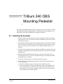
1
Trillium 240 OBS User Guide Nanometrics Inc. Kanata, Ontario Canada © 2005–2006 Nanometrics Inc. All Rights Reserved. Trillium 240 OBS User Guide The information in this document has been carefully reviewed and is believed to be reliable. Nanometrics, Inc. reserves the right to make changes at any time without notice to improve the reliability and function of the product. No part of this publication may be reproduced, stored in a retrieval system or transmitted, in any form or by any means, electronic, mechanical, photocopying, recording, or otherwise, without the prior written permission of Nanometrics Inc. Nanometrics, Inc. 250 Herzberg Road Kanata, Ontario, Canada K2K 2A1 Tel (613)592-6776 Fax (613)592-5929 Email [email protected] www.nanometrics.ca Part number 15857R2 Release date 2006-02-08 Contents Figures . . . . . . . . . . . . . . . . . . . . . . . . . . . . . . . . . . . . . . . . . . . . . . . . . . . . . . . . . . v Tables . . . . . . . . . . . . . . . . . . . . . . . . . . . . . . . . . . . . . . . . . . . . . . . . . . . . . . . . . vii Chapter 1 Introduction . . . . . . . . . . . . . . . . . . . . . . . . . . . . . . . . . . . . . . . . . . . . . . . . . . . . . . 1 Chapter 2 Installation . . . . . . . . . . . . . . . . . . . . . . . . . . . . . . . . . . . . . . . . . . . . . . . . . . . . . . . 3 2.1 Unpacking the sensor . . . . . . . . . . . . . . . . . . . . . . . . . . . . . . . . . . . . . . . . . . . . . . . . . . . . . 2.2 Installing the sensor . . . . . . . . . . . . . . . . . . . . . . . . . . . . . . . . . . . . . . . . . . . . . . . . . . . . . . 2.3 Installing the sensor cable . . . . . . . . . . . . . . . . . . . . . . . . . . . . . . . . . . . . . . . . . . . . . . . . . 2.4 Mass centring . . . . . . . . . . . . . . . . . . . . . . . . . . . . . . . . . . . . . . . . . . . . . . . . . . . . . . . . . . . 2.4.1 Tilt tolerance. . . . . . . . . . . . . . . . . . . . . . . . . . . . . . . . . . . . . . . . . . . . . . . . . . . . . . . . . . . 2.4.2 Mechanical mass centring . . . . . . . . . . . . . . . . . . . . . . . . . . . . . . . . . . . . . . . . . . . . . . . . 2.4.2.1 Choosing when to initiate mass centring . . . . . . . . . . . . . . . . . . . . . . . . . . . . . . . . . . . . 2.4.2.2 How to initiate mass centring. . . . . . . . . . . . . . . . . . . . . . . . . . . . . . . . . . . . . . . . . . . . . 2.4.3 Continuous electronic mass recentring . . . . . . . . . . . . . . . . . . . . . . . . . . . . . . . . . . . . . . 2.4.3.1 Mass recentring status . . . . . . . . . . . . . . . . . . . . . . . . . . . . . . . . . . . . . . . . . . . . . . . . . 2.4.4 Mass centring procedure . . . . . . . . . . . . . . . . . . . . . . . . . . . . . . . . . . . . . . . . . . . . . . . . . 2.5 Installation checklist . . . . . . . . . . . . . . . . . . . . . . . . . . . . . . . . . . . . . . . . . . . . . . . . . . . . . . 3 3 3 4 4 4 4 5 5 5 5 6 Chapter 3 Operation . . . . . . . . . . . . . . . . . . . . . . . . . . . . . . . . . . . . . . . . . . . . . . . . . . . . . . . . 7 3.1 External connector . . . . . . . . . . . . . . . . . . . . . . . . . . . . . . . . . . . . . . . . . . . . . . . . . . . . . . . 7 3.2 Sensor power . . . . . . . . . . . . . . . . . . . . . . . . . . . . . . . . . . . . . . . . . . . . . . . . . . . . . . . . . . . 7 3.3 Control signals . . . . . . . . . . . . . . . . . . . . . . . . . . . . . . . . . . . . . . . . . . . . . . . . . . . . . . . . . . 8 3.4 Output signals. . . . . . . . . . . . . . . . . . . . . . . . . . . . . . . . . . . . . . . . . . . . . . . . . . . . . . . . . . . 8 3.5 Frequency response . . . . . . . . . . . . . . . . . . . . . . . . . . . . . . . . . . . . . . . . . . . . . . . . . . . . . 10 3.6 Self-noise . . . . . . . . . . . . . . . . . . . . . . . . . . . . . . . . . . . . . . . . . . . . . . . . . . . . . . . . . . . . . 11 3.7 Calibration. . . . . . . . . . . . . . . . . . . . . . . . . . . . . . . . . . . . . . . . . . . . . . . . . . . . . . . . . . . . . 13 3.8 State-of-Health . . . . . . . . . . . . . . . . . . . . . . . . . . . . . . . . . . . . . . . . . . . . . . . . . . . . . . . . . 14 3.9 Connecting and configuring the serial port . . . . . . . . . . . . . . . . . . . . . . . . . . . . . . . . . . . . 14 3.10 Troubleshooting and maintenance . . . . . . . . . . . . . . . . . . . . . . . . . . . . . . . . . . . . . . . . . . 18 Appendix A Specifications . . . . . . . . . . . . . . . . . . . . . . . . . . . . . . . . . . . . . . . . . . . . . . . . . . . . 19 A.1 A.2 A.3 A.4 A.5 A.6 Technology . . . . . . . . . . . . . . . . . . . . . . . . . . . . . . . . . . . . . . . . . . . . . . . . . . . . . . . . . . . . Performance . . . . . . . . . . . . . . . . . . . . . . . . . . . . . . . . . . . . . . . . . . . . . . . . . . . . . . . . . . . Interface . . . . . . . . . . . . . . . . . . . . . . . . . . . . . . . . . . . . . . . . . . . . . . . . . . . . . . . . . . . . . . Power . . . . . . . . . . . . . . . . . . . . . . . . . . . . . . . . . . . . . . . . . . . . . . . . . . . . . . . . . . . . . . . . Physical . . . . . . . . . . . . . . . . . . . . . . . . . . . . . . . . . . . . . . . . . . . . . . . . . . . . . . . . . . . . . . Environmental. . . . . . . . . . . . . . . . . . . . . . . . . . . . . . . . . . . . . . . . . . . . . . . . . . . . . . . . . . 19 19 20 20 20 20 iii Contents Appendix B Connector Pinout . . . . . . . . . . . . . . . . . . . . . . . . . . . . . . . . . . . . . . . . . . . . . . . . . 21 Appendix C Generic Sensor Cable . . . . . . . . . . . . . . . . . . . . . . . . . . . . . . . . . . . . . . . . . . . . . 23 Appendix D Cable Design . . . . . . . . . . . . . . . . . . . . . . . . . . . . . . . . . . . . . . . . . . . . . . . . . . . . 25 Appendix E Trillium 240 OBS Mounting Pedestal . . . . . . . . . . . . . . . . . . . . . . . . . . . . . . . . . . 27 E.1 Installing the Pedestal. . . . . . . . . . . . . . . . . . . . . . . . . . . . . . . . . . . . . . . . . . . . . . . . . . . . 27 E.2 Levelling the assembly . . . . . . . . . . . . . . . . . . . . . . . . . . . . . . . . . . . . . . . . . . . . . . . . . . . 28 Appendix F Alignment and Mounting Features . . . . . . . . . . . . . . . . . . . . . . . . . . . . . . . . . . . . 31 iv Figures 1-1 Trillium 240 OBS (shown with optional Mounting Pedestal) . . . . . . . . . . . . . . . . . . . . . . . 1 3-1 Sensor axis orientations. . . . . . . . . . . . . . . . . . . . . . . . . . . . . . . . . . . . . . . . . . . . . . . . . . . 9 3-2 Nominal frequency response . . . . . . . . . . . . . . . . . . . . . . . . . . . . . . . . . . . . . . . . . . . . . . 11 3-3 Trillium 240 OBS self-noise . . . . . . . . . . . . . . . . . . . . . . . . . . . . . . . . . . . . . . . . . . . . . . . 12 3-4 Trillium 240 OBS performance. . . . . . . . . . . . . . . . . . . . . . . . . . . . . . . . . . . . . . . . . . . . . 13 E-1 Mounting the Trillium 240 OBS on the Pedestal . . . . . . . . . . . . . . . . . . . . . . . . . . . . . . . 29 F-1 Alignment and mounting features . . . . . . . . . . . . . . . . . . . . . . . . . . . . . . . . . . . . . . . . . . 32 v Figures vi Tables 2-1 Mass position output voltage indicating need for mass centring . . . . . . . . . . . . . . . . . . . . 6 3-1 Axis orientation and polarity of XYZ outputs . . . . . . . . . . . . . . . . . . . . . . . . . . . . . . . . . . . 8 3-2 Poles and zeroes . . . . . . . . . . . . . . . . . . . . . . . . . . . . . . . . . . . . . . . . . . . . . . . . . . . . . . . 10 3-3 Serial port commands . . . . . . . . . . . . . . . . . . . . . . . . . . . . . . . . . . . . . . . . . . . . . . . . . . . 15 B-1 Connector pinout . . . . . . . . . . . . . . . . . . . . . . . . . . . . . . . . . . . . . . . . . . . . . . . . . . . . . . . 21 C-1 Generic sensor cable wiring for CBL13942R2 . . . . . . . . . . . . . . . . . . . . . . . . . . . . . . . . . 24 vii Tables viii Chapter 1 Introduction Trillium Model 240 OBS is a three-component, very broadband low-noise seismometer, designed for deployment in a suitable ocean bottom seismograph system. Its extended low frequency range useful out to beyond 1000 seconds, low noise, and wide dynamic range make it ideal for teleseismic studies as well as for regional and local events. Figure 1-1 Trillium 240 OBS (shown with optional Mounting Pedestal) The Trillium 240 OBS has an internal, automated mass centring capability which facilitates both local and remote recentring. Trillium seismometers have a symmetric triaxial arrangement of the sensing elements. The use of three identical axis elements ensures the same frequency response for ver- 15857R2 2006-02-08 Trillium 240 OBS User Guide 1 Chapter 1: Introduction tical and horizontal outputs, is less susceptible to rapid changes in temperature, and guarantees true orthogonality of the three outputs. Data output of XYZ or UVW can be selected remotely, allowing calibration of the elements independently of the electronics. UVW data may also be used instead of XYZ for seismic signal recording, if desired. The Trillium 240 OBS is designed to be installed on a gimbal-mounted platform in a pressure-controlled bathysphere. The Trillium 240 OBS case is designed to occupy a minimum volume and will not attenuate atmospheric pressure variations as well as the land-based Trillium 240. To facilitate land-based testing and setup of the Trillium 240 OBS, an optional Mounting Pedestal is available which includes alignment markings, adjustable locking levelling feet, and a precision bubble level. Please read the appropriate sections of this manual before transporting, storing, installing, or operating the Trillium 240 OBS. If you need technical support, please submit your request by email or fax. Include a full explanation of the problem and supporting data, to help us direct your request to the most knowledgeable person for reply. Before returning a unit for repair, contact Nanometrics Support to obtain an RMA number. Email: [email protected] FAX: To: Support +1 (613) 592-5929 2 Trillium 240 OBS User Guide 15857R2 2006-02-08 Chapter 2 Installation This chapter provides an overview of installation and mass centring procedures for the Trillium 240 OBS. Section 2.5 on page 6 provides a generic installation checklist. 2.1 Unpacking the sensor Trillium 240 OBS is shipped in a very sturdy triple-wall coated cardboard box with custom-cut cushioning foam. To minimize the possibility of damaging the sensor, do not remove it from the box until it is ready to be placed in the pressure case. Save the shipping box and foam in case the sensor needs to be shipped again. 2.2 Installing the sensor The Trillium 240 OBS is designed to be installed on a gimbal-mounted platform in a pressure-controlled bathysphere. The Trillium 240 OBS has two sets of mounting features, to allow the sensor to be installed on either a plate with bosses or an annular ring. See Appendix F for information about the mounting and alignment features. Do not exceed the maximum recommended torque value for the screw type and host material when installing the Trillium 240 OBS on your platform. The Trillium 240 OBS base is aluminum. For land-based testing and setup of the Trillium 240 OBS you can use the optional Mounting Pedestal; see Appendix E. 2.3 Installing the sensor cable 1. Connect the sensor cable. The cable should be strain-relieved at some point close to the sensor, for example with tie-wraps and tie-wrap anchors. Ensure that the cable does not interfere with either the levelling mechanism or the sensor measurements (for example, by impinging on the sensor case). 2. Ensure that the digitizer case is solidly earthed, and that the outer shield of the cable and the sensor case are thereby earthed. 15857R2 2006-02-08 Trillium 240 OBS User Guide 3 Chapter 2: Installation 2.4 Mass centring The Trillium 240 OBS has an automated mechanical mass centring capability that uses a precision stepper motor to centre the boom of the pendulum of each axis exactly at the null point. The motor adjusts the tension on the spring which supports the boom, to compensate both for tilt from absolute level and for the ambient temperature in which the unit is operating. As well, the sensor automatically recentres the masses electronically to compensate for gradual changes in temperature, up to a range of ±10°C difference from when mechanical mass centring was last initiated. 2.4.1 Tilt tolerance The Trillium 240 OBS can be mass centred if the sensor is within ±1.0° of level, although it is good practice to ensure the sensor is levelled as precisely as possible before centring the masses. Once the Trillium 240 OBS has been precisely mass centred (that is, the mass position voltage is within the range ±0.3 V), the sensor can tolerate a shift of up to ±0.03° without mass recentring being required. 2.4.2 Mechanical mass centring The operation of mass centring typically takes less than 1 minute. It may take up to 5 minutes if the unit is compensating for substantially different tilt than it had when it was last centred. 2.4.2.1 Choosing when to initiate mass centring While mass centring can be done immediately after installing and levelling the Trillium 240 OBS, it is best to initiate mass centring again at least 6 hours after installation, when the temperature has fully equalized. This ensures the unit will then be able to tolerate up to ±10°C range variation in ambient temperature without requiring recentring. It is best to initiate mechanical mass centring when the ambient temperature is roughly in the centre of its expected range, rather that at one extreme or the other, to make the most of the usable 20°C range the unit can tolerate without mechanical recentring. Mass centring should only be done when interruption of good-quality seismic data can be tolerated, as there are temporary effects on the output signal. When the mass centring motors are operating, the sensor transfer function is set to a “short period” mode, and the motion of the boom during the recentring is very evident in the output signal. When the mass centring operation is complete, the sensor reverts to the mode it was in before mass centring was initiated (generally “long period” mode). At this time, there may be a transient superimposed on the output signal that takes some minutes to decay. To determine whether mass centring needs to be done you can check the voltage readings on the mass position outputs for each of the three sensor channels (signals U_MP, V_MP, and W_MP, referenced to AGND): • If the values are outside the range ±3.5V the sensor may not be able to report seismic signals properly. For this condition, mass centring must be done. 4 Trillium 240 OBS User Guide 15857R2 2006-02-08 Chapter 2: Installation • If the values are within the range ±3.5V but not within the range ±2V the sensor is sufficiently centred that it will report seismic signals properly. However, it is strongly recommended the masses be recentred. • If the values are within the range ±2V but not within the range ±0.3V the sensor is sufficiently centred that it will report seismic signals properly. However, the closer the mass positions are to 0V, the more room there is to tolerate further ambient temperature changes. For this condition, centring the masses is recommended if it is convenient to do so. • If the mass positions are all within the range ±0.3V there is no need to recentre, although it can be done if desired. 2.4.2.2 How to initiate mass centring You can initiate mass centring using either of these two methods: Pull the MC/RX pin high for at least 1 second (referenced to DGND). Issue a Center command using the RS-232 digital interface (see Section 3.9 on page 14). 2.4.3 Continuous electronic mass recentring Continuous electronic mass recentring compensates for gradual changes in temperature, up to a range of ±10°C difference from when mechanical mass centring was last initiated. If the temperature changes more than 10°C, the unit may need to be mechanically mass centred. 2.4.3.1 Mass recentring status The mass position status is reported via analog signals U_MP, V_MP, and W_MP, referenced to AGND (pins E, F, S, and V respectively) which operate roughly in the range ±4V. A 0V signal means the axis boom is perfectly centred. A signal exceeding ±2V indicates mechanical mass recentring should be initiated. These signals respond very slowly to changes in tilt, mass position, or temperature when the sensor is in the normal operating “long period” mode, but respond almost instantly (within a second) when the sensor is set to “short period” mode. The mass position status is also reported digitally via the RS-232 serial interface (see Section 3.9 on page 14). 2.4.4 Mass centring procedure When using a Nanometrics digitizer such as a Taurus or Trident that is connected to a network, you can read the mass position status and initiate mass centring remotely. For the Taurus, use options in the Sensor page either locally or on an external browser. The Taurus also provides a mass auto-centring feature. For the Trident, use options in the Nanometrics UI, or use NaqsView. 1. Install and level the Trillium 240 OBS as precisely as possible. For best results, centre masses immediately after installing and levelling the Trillium 240 OBS, and again at least 6 hours after installation when the temper- 15857R2 2006-02-08 Trillium 240 OBS User Guide 5 Chapter 2: Installation ature has fully equalized. This ensures the unit will then be able to tolerate up to ±10°C range variation in ambient temperature without requiring recentring. 2. Check the voltage readings on the mass position outputs for each of the three sensor channels (signals U_MP, V_MP, and W_MP, referenced to AGND) to determine whether mass centring needs to be done (Table 2-1). Table 2-1 Mass position output voltage indicating need for mass centring Mass position output voltage Need to centre the masses? outside the range ±3.5V yes within the range ±3.5V but not within the range ±2V strongly recommended within the range ±2V but not within the range ±0.3V recommended, if it is convenient mass positions are all within the range ±0.3V no, although it can be done if desired 3. Initiate mass centring by pulling the MC/RX pin high, referenced to DGND (pin R), for at least 1 second. This will initiate mass centring on all three axes in sequence—first axis U, then V, then W. The time for the operation to complete varies from a few seconds to at most 5 minutes, but is typically less than 1 minute. 4. Observe the voltage readings on the mass position outputs to confirm they are now within the ±0.3V range. Note that the sensor is temporarily put into “short period mode” during the centring operation, and the previous mode is automatically restored when the centring operation is complete. 2.5 Installation checklist Sensor serial number is noted Cable is connected to the sensor and the digitizer Cable is strain-relieved close to the sensor Cable will not impinge on the sensor case after levelling Masses are centred after temperature equalization (at least 6 hours post-installation) 6 Trillium 240 OBS User Guide 15857R2 2006-02-08 Chapter 3 Operation This chapter provides operating parameters and instructions for the Trillium 240 OBS. 3.1 External connector The Trillium 240 OBS connector is a 19-pin male military circular type hermetic connector. The pinout is given in Appendix B. 3.2 Sensor power The Trillium 240 OBS can be powered using a DC source that can sustain 9V to 36V at the sensor connector. Voltage drops over the cable must be accounted for, and so the supply voltage at the source may need to be higher. In normal operation (the sensor is level and well centred, there is a low seismic signal, the sensor has settled for at least 30 minutes, and serial transmit is disabled) the power consumption is typically 650mW. On startup, the peak power surge may be up to 4.5W briefly. Power consumption above normal quiescent after the initial power on in-rush is roughly proportional to the output signal. If the sensor is not centred or has not yet settled, the output signals will be at the maximum, and power consumption may be as high as 3W. For a settled, centred, and level sensor, a seismic signal that approaches the sensor’s maximum clip level may draw as much as 2W peak (the average power consumption would be much lower). The mass centring operation will draw additional power, up to an incremental 2W while the motors are operating. For long cables, be sure to account for the resistive voltage drop due to the cable itself. For example, 50m of 24AWG wire has a resistance of 4.2Ω in each direction. Therefore the voltage drop due to the possible 500mA startup in-rush at 9V would be 4.2V, and the power supply must be able to briefly supply 13.2V for this length of cable. The supply should also be able to sustain a 2W peak output at a voltage that guarantees the sensor receives 9V. For the 50m cable example, the peak current would be 220mA at 9V, and the voltage drop would be 1.9V, so the supply must be able to provide 220mA at 10.9V to reliably power the sensor for maximum seismic signals when using a 50m cable. 15857R2 2006-02-08 Trillium 240 OBS User Guide 7 Chapter 3: Operation 3.3 Control signals Trillium 240 OBS has 5 digital control inputs: MC/RX, UVW/TX, U_CALEN, V_CALEN and W_CALEN. All of these inputs are optically isolated from both the input voltage and the output and calibration input signals. Therefore, signals applied to these pins must be referenced to DGND rather than ±PWR or AGND. All of these inputs are active-high. Specifically, any voltage greater than 3.5V at a current greater than 0.1mA enables the relevant functionality while any voltage less than 1V or a high impedance disables it. All inputs can tolerate at least ±15V except for UVW/TX which can tolerate voltages from –7V to +15V. 3.4 Output signals The sensitivity specified in Table 3-2 on page 10 assumes an infinite input impedance at the digitizer. For digitizers with low input impedance it will become necessary to account for the fact that source impedance of the differential outputs is 300Ω ±1% (150Ω each output). A control signal switches the Trillium 240 OBS output signal to either UVW output or XYZ output. The “natural” sensor output is UVW; in this mode the outputs represent the actual motion of the masses of the three sensor components. The “conventional” sensor output is XYZ; in this mode the outputs represent horizontal and vertical motion. See Table 3-1 for the polarities of the XYZ outputs and their correspondence to the directions of the compass. Table 3-1 Axis orientation and polarity of XYZ outputs Axis Orientation Positive voltage represents ... X east-west ... case motion to east Y north-south ... case motion to north Z vertical ... case motion upwards To select the sensor outputs: To select the UVW outputs, pull the UVW/TX pin high. To select the XYZ outputs, either leave the UVW/TX pin floating or set it to 0V. The sensor responds to changes on this control line within 4 seconds. Note that this input control signal is disabled when the sensor is transmitting on the serial port, since this pin is then used as the RS-232 serial TX output signal. (See Section 3.9, “Connecting and configuring the serial port,” on page 14.) To understand the difference between the UVW and XYZ outputs, refer to Figure 3-1. The sensor axes have been designed so that they are identical and so that the directions in which they sense motion are orthogonal. The U axis was chosen to be aligned with the East-West axis when projected into the horizontal plane. 8 Trillium 240 OBS User Guide 15857R2 2006-02-08 Chapter 3: Operation Figure 3-1 Sensor axis orientations Z V Y U W X This arrangement results in the following transformation equations: 2 0 u 1-----= ⋅ v –1 3 6 w –1 – 3 x 1 y = ------- ⋅ 6 z 2 x ⋅ y 2 z 2 (EQ 1) 2 –1 –1 0 2 u 3 – 3 ⋅ v w 2 2 (EQ 2) The first equation is implemented mechanically in the orientation of the Trillium 240 OBS individual sensor axes. The second equation is implemented electronically when the Trillium 240 OBS is in XYZ mode. Alternatively, seismic data may be digitized with the Trillium 240 OBS in UVW mode and the transformation to horizontal and vertical signals implemented optionally when the data are processed. This allows for studies and calibrations where both UVW and XYZ data are required. 15857R2 2006-02-08 Trillium 240 OBS User Guide 9 Chapter 3: Operation 3.5 Frequency response The frequency response of the Trillium 240 OBS can be measured using the calibration coil. The measured response is the product of the calibration system’s (first-order low pass) response and the sensor’s own response. The nominal Trillium 240 OBS response is obtained by dividing the nominal sensor calibration result by the calibration system’s transfer function; the three frequency response functions are shown in Figure 3-2. The calibration system’s low-pass response cancels the zero at –161 rad/s in the sensor transfer function when the sensor frequency response is measured using the calibration coil. The nominal poles ( p n ), zeroes ( z n ), normalization factor ( k ), and normalization frequency of the Trillium 240 OBS are shown in Table 3-2. These parameters define the transfer function according to this equation: ∏ ( s + zn ) V ⋅ sn --------F(s) = S sensor ⋅ k ⋅ --------------------------m ∏ ( s + pn ) (EQ 3) n The normalization factor is defined according to this equation: 1 k = ---------------------------------------------------∏ ( i ⋅ 2 ⋅ π ⋅ f0 + zn ) (EQ 4) n ------------------------------------------------∏ ( i ⋅ 2 ⋅ π ⋅ f0 + pn ) n Table 3-2 Poles and zeroes Parameter zn Zeroes Nominal values Units 0 0 –108 –161 rad/s –0.01815 ±0.01799i 10 –173 –196 ±231i –732 ±1415i pn Poles k Normalization factor 2.316 x 10⁹ S sensor Passband sensitivity at 1Hz 1196.5 V·s/m f0 Normalization frequency 1 Hz Trillium 240 OBS User Guide rad/s 15857R2 2006-02-08 Chapter 3: Operation The transfer function is approximately flat out to 240s and rolls off at 40dB/decade below the lower corner frequency, as shown in Figure 3-2. Figure 3-2 Nominal frequency response 3.6 Self-noise Typical Trillium 240 OBS self-noise is plotted in Figure 3-3. Three curves are included for reference: Peterson’s new low-noise model (NLNM) and new high-noise model (NHNM), and McNamara and Buland’s PDF Mode Low Noise Model (MLNM).1 The noise floor shown is the typical level of instrument self-noise assuming proper installation. 1. See also: Peterson, J. (1993). Observations and Modeling of Seismic Background Noise. Open-file report 93-922, U. S. Geological Survey. McNamara, D.E., and R. P. Buland (1994). Ambient Noise Levels in the Continental United States. Bull. Seism. Soc. Am., 94, 1517–1527. Clinton, J. F., and T. H. Heaton (2002). Potential Advantages of a Strong-motion Velocity Meter over a Strong-motion Accelerometer. Seism. Res. Lett., 73, 332–342. 15857R2 2006-02-08 Trillium 240 OBS User Guide 11 Chapter 3: Operation Figure 3-3 Trillium 240 OBS self-noise To determine the dynamic range at frequencies of interest for your application, compare the noise floor to the sensor clip level using Figure 3-4. In this figure, for comparison of noise floors to clip levels, we convert power spectral densities using octave bandwidths and an RMS-to-peak conversion factor of 1.253. 12 Trillium 240 OBS User Guide 15857R2 2006-02-08 Chapter 3: Operation Figure 3-4 Trillium 240 OBS performance 3.7 Calibration Calibration inputs are provided to allow for relative calibration of the sensor across frequency and over time. Since the Trillium 240 OBS is a symmetric triaxial sensor, calibration must be performed on the individual sensor axes (UVW) rather than the horizontal and vertical outputs (XYZ). Individual axis outputs can be digitized by placing the sensor in UVW mode (see Section 3.4). 15857R2 2006-02-08 Trillium 240 OBS User Guide 13 Chapter 3: Operation Each axis has a separate calibration enable signal: U_CALEN, V_CALEN, W_CALEN. All axes use a common calibration input signal (CAL_SIG) which has a sensitivity of 0.010m/s2·V. 3.8 State-of-Health Mass position output signals U_MP, V_MP, and W_MP are provided to monitor the effect of tilt and temperature on the spring which sets the rest position of the boom. As with the calibration signals, they represent the state of the individual sensor axes (UVW) rather than the horizontal and vertical outputs (XYZ). The mass positions are zeroed by initiating the automatic mass centring feature, which uses stepper motors to precisely tension the spring. (See Section 2.4 on page 4 for a discussion of these signals.) If the mass positions are all within the range ±0.3V, then there is no need for recentring. Otherwise follow the procedure in Section 2.4.4, “Mass centring procedure,” on page 5. 3.9 Connecting and configuring the serial port 1. Connect an appropriate RS-232 communications device (such as a PC serial port) to the sensor by connecting its TX pin to the MC/RX signal (pin C) and its RX pin to the UVW/TX signal (pin D). Be sure to take appropriate precautions for signal shielding and grounding to avoid introducing unwanted noise into the sensor or onto adjacent signal wires in the cable, or the seismic signal from the sensor may become noisy. 2. Set the serial port on the communicating device to use this configuration: • Speed: 9600 baud • Data Bits: 8 • Parity: None • Stop bits: 1 • Flow Control: Xon/Xoff 3. If you are using a terminal emulator program, enable these settings: • Echo typed characters locally – The Trillium 240 OBS serial port does not echo received characters on its transmit port. • “Send line ends with line feeds” or equivalent – The serial port expects all commands to be terminated with the “carriage return” character (ASCII 0x0D). 4. Once the sensor is powered up and an appropriate serial device connected as above, send the characters Tx<CR> (the <CR> denotes the “carriage return” character). Note that the serial commands are not case-sensitive; Tx, TX, and tx are equivalent. After a delay of 3 seconds the sensor will turn enable the UVW/TX output and transmit Serial Transmit Enabled<LF><CR>. 5. To view help on the commands, send the help command Help<CR> to get the sensor to transmit a help page, displaying the various commands and syntax. This is what would be displayed: 14 Trillium 240 OBS User Guide 15857R2 2006-02-08 Chapter 3: Operation Nanometrics Trillium User Menu (Version 3.30) Program A ********************************************************************* Help - Repeat this menu (also turns on Serial TX) Tx - Enable the Serial Transmit Signal TxOff - Disable the Serial Transmit Signal Upload - Upload software to the alternate program Switch - Switch to the alternate program Default - Set the current program as default Reboot - Reboot the instrument GetInfo - Get factory configuration information ReadFC - Read factory calibration parameters WriteUC - Write user calibration parameters ReadUC - Read the user calibration parameters Soh - Report state-of-health ShortPer - Set sensor to short period mode LongPer - Set sensor to long period mode SetXYZ - Set sensor to XYZ mode SetUVW - Set sensor to UVW mode Center - Center all masses or (u, v, w) CheckSum - Print checksum value for both program A and B ********************************************************************* Please type a command and hit return: Each of the serial port commands is described in Table 3-3. Table 3-3 Serial port commands Command Description Help - Repeat this menu (also turns on Serial TX) Use the Help command to view the list of commands. The first line identifies the firmware version in use, and whether it is Program A or Program B. The Help command also turns on the TX signal if it has not already been turned on (after a delay of 3 seconds). It is the only command besides Tx that will enable the sensor’s serial transmit signal. Tx - Enable the Serial Transmit Signal The Tx command turns on the sensor’s serial transmit signal (signal UVW/TX, pin D) after a delay of 3 seconds, and sends the message Serial Transmit Enabled<LF><CR>. The serial transmit port stays enabled until turned off by the TxOff command or by cycling the power to the sensor. In this mode, the UVW/TX pin must not be used as an input pin for UVW mode. TxOff - Disable the Serial Transmit Signal The TxOff command turns off the sensor’s serial transmit signal (signal UVW/TX, pin D) and then waits 3 seconds. After the 3-second delay, this pin will be interpreted as the UVW mode input pin. Upload - Upload software to the alternate program Caution Please DO NOT use the Upload command unless specifically directed by Nanometrics Technical Support, as it erases the firmware in the alternate partition. The Upload command uploads a new version of firmware to the firmware partition (A or B) that is not currently running. 15857R2 2006-02-08 Trillium 240 OBS User Guide 15 Chapter 3: Operation Table 3-3 Serial port commands (Continued) Command Description Switch - Switch to the alternate program There are two instances of firmware loaded in the Trillium 240 OBS, which can be the same version or different versions, one loaded in partition A, the other in partition B. The sensor will run the firmware from the default partition on power up. Use the Switch command to switch immediately to running the firmware in the other partition. It does not change which partition is the default, so that when the sensor is power cycled, it will start up in the original default partition. For example, if the default partition is “B” and the Switch command is executed, then partition A firmware is run immediately. When the sensor is powered off and then on again, it then switches back to running Partition B firmware. Use the CheckSum command to ensure there is valid code in both partitions before switching. Default - Set the current program as default Use the Default command to set the running firmware partition to be the default partition loaded at power up. For example, if the sensor is running partition A by default on power up, to change to running partition B instead, the procedure is: 1. Execute the SOH command to verify that partition A is running. 2. Use the Checksum command to verify that there is valid code in both partitions. 3. Execute the Switch command to change to running partition B, and the SOH command to verify that the new firmware is running. 4. Execute the Default command to set partition B to be the default on power up. Reboot - Reboot the instrument Use the Reboot command to restart the firmware. GetInfo - Get factory configuration information ReadFC - Read factory calibration parameters Use the commands GetInfo and ReadFC to read factory information stored in the Trillium 240 OBS. Factory configuration information includes model, version, and serial numbers; and other factory information for the unit, axes, and various circuit boards in the sensor. This information is primarily used by Nanometrics Technical Support. Factory calibration parameters may include information regarding measured sensitivity, transfer function, and the like. WriteUC - Write user calibration parameters Use the command WriteUC to upload calibration information from a text file in Turtle format. (You can use ReadFC to view the factory calibration information for an example of the syntax. For information on Turtle, see http://www.ilrt.bris.ac.uk/discovery/2004/01/turtle/. For information on RDF in general, see http://www.w3.org/RDF/.) ReadUC - Read the user calibration parameters Use the ReadUC command to display calibration information stored using the WriteUC command. 16 Trillium 240 OBS User Guide 15857R2 2006-02-08 Chapter 3: Operation Table 3-3 Serial port commands (Continued) Command Description Soh - Report state-ofhealth Use the SOH command to view state-of-health information as listed below. <SOH> <Manufacture>"Nanometrics, Inc."</Manufacture> <Product>"Trillium Firmware"</Product> <Version>3.30</Version> <Temperature>26.22</Temperature> <Mass>U=0.030 V=0.497 W=0.063</Mass> <Adc>U=14 V=225 W=29</Adc> <Modes>Period=Long Channel=XYZ</Modes> <Positions>U=380 V=-66 W=-110</Positions> <Zeros>U=0 V=0 W=0</Zeros> <Range>U=7043 V=7371 W=7151</Range> </SOH> • <Version> – The version of the firmware that is currently running. • <Temperature> – The temperature near the main electronics PCB, which is located in a chamber near the top of the unit. The temperature of the axes will likely be different from this. • The mass positions for each axis (U, V, W). These are reported in two forms: • <Mass> – decimal numbers with a ±4.2 range that roughly corresponds to the output voltage at the U_MP, V_MP, and W_MP signals. • <ADC> – proportional integer numbers with a range of ±1900. The <ADC> number is about 452 times the <Mass> decimal number. • <Modes> – The sensor modes are reported, including whether the sensor is in long period or short period mode, and whether the seismic signals are output in XYZ or UVW mode. • The <Range>, <Positions>, and <Zeros> numbers pertain to the mass recentring stepper motors: • The <Range> number is the full range in steps the mass positioning stepper motor can traverse between the two optical limit switches. This is measured and set at the factory for each axis. • The <Positions> number is the current position of the stepper motor relative to the midpoint of the total range. A number close to zero means the mass positioning mechanism is near the midpoint of the range and has lots of room for further adjustment. A positive or negative number close to half the <Range> number means the mass positioning mechanism is near to the limit of its adjustment range. • The <Zeros> number is the position of the stepper motor which corresponds to the sensor being level. If the <Position> number is close to the <Zeros> number for all axes, the sensor is close to nominally level. The <Zeros> number is set at the factory for each axis. 15857R2 2006-02-08 Trillium 240 OBS User Guide 17 Chapter 3: Operation Table 3-3 Serial port commands (Continued) Command Description ShortPer - Set sensor to short period mode LongPer - Set sensor to long period mode Use the ShortPer and LongPer commands to set the electronic mass centring response of the sensor to short period or to long period respectively. • Short period is used when mechanically recentring the masses, and is automatically invoked when the mass recentring is initiated. (The prior mode is restored when mass centring completes.) • Long period mode is the normal mode for collecting seismic data, and is essential to obtain the low frequency broadband performance. Short period mode is useful to see the mass positions respond quickly (signals U_MP, V_MP, W_MP, or the SOH <Mass> or <ADC> values) when the sensor is being levelled. In long period mode these numbers ramp very slowly, and so care must be taken to not be misled by apparently centred values when in fact the sensor is not centred. In short period mode, these numbers respond within a second. The sensor always powers up in long period mode. Long period is the normal response for a 240 second lower corner frequency. SetXYZ - Set sensor to XYZ mode SetUVW - Set sensor to UVW mode Use the SetXYZ and SetUVW commands to set the seismic output signals to the conventional XYZ (horizontals and vertical) mode, or to the “natural” UVW mode in which the output of each axis is given directly. XYZ mode is the default. Note that this mode is also set by the UVW/TX input line when the sensor is not in Serial Transmit mode. The sensor responds to whichever command (serial port or control line) last signalled a change. Center - Center all masses or (u, v, w) You can use the Center command with or without parameters: • Without parameters, Center initiates mass centring for all channels, which can also be initiated by pulling the MC/RX pin high for at least 1 second (referenced to DGND). • With a parameter (u, v, or w), Center will centre the specified axis without disturbing the other axes; for example, Center V centres the V axis only. CheckSum - Print checksum values for both program A and B Use the CheckSum command to check the firmware checksums of both partitions and what they should be. This is useful to ensure there is valid code in each partition (for example, before switching to the alternate firmware partition). 3.10 Troubleshooting and maintenance The Trillium 240 OBS mechanical and electronic elements have been designed to be robust and reliable, to ensure there is no need to open units for on-site maintenance. The internal reverse-voltage protection and over-current protection automatically resets when the fault is removed, so there are no fuses to replace. The automatic mass tensioner mechanism is designed to be jam-proof. In the unlikely event the sensor does not operate correctly, please contact Nanometrics support (see Chapter 1, “Introduction”). 18 Trillium 240 OBS User Guide 15857R2 2006-02-08 Appendix A Specifications This section lists the specifications of the Trillium 240 OBS. A.1 Technology Topology Symmetric triaxial Feedback Coil-magnet force feedback with capacitive transducer Mass centring Automatic mechanical recentring, can be remotely initiated Levelling Optional Trillium 240 OBS Mounting Pedestal, includes integrated bubble level and adjustable locking levelling feet A.2 Performance 15857R2 2006-02-08 Self-noise See Figure 3-3 on page 12 Sensitivity 1196V·s/m ±0.5% Bandwidth –3dB points are 244s and 207Hz Transfer function Lower corner poles within ±0.5% of nominal provided High-frequency poles and zeros within ±5% of nominal provided Clip level 15mm/s peak-to-peak differential up to 1.5Hz (see also Figure 3-4 on page 13) Lower corner damping relative to critical 0.707 Output impedance 2·150Ω ±1% Temperature ±10°C without recentring Tilt Operational tilt range ±1° Dynamic tilt Maximum tilt without recentring ±0.03° Trillium 240 OBS User Guide 19 Appendix A: Specifications A.3 Interface Connector 19-pin MIL-C-26482, mounted on base Velocity output Selectable XYZ (east, north, vertical) or UVW mode 40V peak-to-peak differential Mass position output Three independent ±4.5V outputs for UVW Calibration input Remote calibration in XYZ or UVW mode One voltage input for all channels Three separate control signals to enable U, V, or W channels Control inputs Isolated active-high referenced to DGND Serial port RS-232 compatible For instrument control and retrieval of configuration information A.4 Power Supply voltage 9V to 36V DC isolated input Power consumption 650mW typical at 15V input Protection Reverse-voltage protected Self-resetting over-current protection No fuse to replace A.5 Physical Diameter 24.1cm Height 23.6cm including the connector Weight ~9.5kg Parasitic resonances None below 130Hz A.6 Environmental 20 Operating temperature –20°C to 50°C Storage temperature –40°C to 70°C Pressure Designed to be operated at standard atmospheric pressure. Humidity 0 to 100% Shock 20g half sine, 5ms without damage, 6 axes No mass lock required for transport Weather resistance Rated to IP68 and NEMA 6P for outdoor use, dust, and immersion resistance Trillium 240 OBS User Guide 15857R2 2006-02-08 Appendix B Connector Pinout The Trillium 240 OBS connector is a 19-pin male military circular type hermetic connector. The pinout is given in Table B-1. Table B-1 Connector pinout 15857R2 2006-02-08 Pin Name L Z+/W+ M Z–/W– N Y+/V+ A Y–/V– P X+/U+ B X–/U– T CAL_SIG K U_CALEN J V_CALEN U W_CALEN E U_MP F V_MP S W_MP V Function Type vertical (W axis) output north/south (V axis) output 40V peak-to-peak differential east/west (U axis) output calibration signal input 9.2kΩ input impedance 0.010m/s2·V nominal calibration enable inputs active-high 5 to 15V (low = open or 0V) mass position outputs ±4.5V single-ended AGND analog ground N/A H +PWR power input G –PWR power return D UVW/TX • input: enable UVW instead of XYZ outputs • output: serial RS-232 transmit • as UVW input: active-high 5 to 15V; (low = open or 0V) • as TX output: ±5V C MC/RX • input: initiate mass centring • input: serial RS-232 receive • as MC input: active-high 5 to 15V; (low = open or 0V) • as RX input: +5V/0V to ±15V R DGND digital ground N/A shell CHASSIS for shielding and safety N/A 9V to 36V DC isolated Trillium 240 OBS User Guide 21 Appendix B: Connector Pinout 22 Trillium 240 OBS User Guide 15857R2 2006-02-08 Appendix C Generic Sensor Cable A generic sensor cable may have been shipped with your sensor. Table C-1 on page 24 is the wiring key for the standard cable (Nanometrics part number CBL13942R2). This table can be used as a reference when wiring the generic sensor cable end to a digitizer connector. 15857R2 2006-02-08 Trillium 240 OBS User Guide 23 Appendix C: Generic Sensor Cable Table C-1 Generic sensor cable wiring for CBL13942R2 From To Wire Run Conn Pin Name Conn P1 L Z+/W+ P1 M Z–/W– P1 Name Colour P2 CH1+ RED 1 P2 CH1– BLK 1 P2 CH1GND DRAIN 1 P1 N Y+/V+ P2 CH2+ WHT 2 P1 A Y–/V– P2 CH2– BLK 2 P2 CH2GND DRAIN 2 P1 P1 P X+/U+ P2 CH3+ GRN 3 P1 B X–/U– P2 CH3– BLK 3 P2 CH3GND DRAIN 3 P1 P1 T CAL_SIG P2 CAL1+ BLU 4 P1 U W_CALEN P2 CAL1–/CTRL4 BLK 4 SHELL P2 SHELL DRAIN 4 P1 P1 J V_CALEN P2 CAL2–/CTRL5 YEL 5 P1 K U_CALEN P2 CAL3–/CTRL6 BLK 5 SHELL P2 SHELL DRAIN 5 P1 P1 S W_MP P2 EXT_SOH1 BRN 6 P1 F V_MP P2 EXT_SOH2 BLK 6 SHELL P2 SHELL DRAIN 6 P1 P1 E U_MP P2 EXT_SOH3 ORG 7 P1 V AGND P1 CH1GND BLK 7 SHELL P2 SHELL DRAIN 7 P1 P1 H +PWR P2 SEN+12V RED 8 P1 G –PWR P2 SENRTN WHT 8 SHELL P2 SHELL DRAIN 8 P1 P1 D UVW/TX P2 CTRL1 RED 9 P1 C MC/RX P2 CTRL2 GRN 9 P1 R DGND P2 DGND DRAIN 9 SHELL P2 SHELL BRAID P1 24 Pin Trillium 240 OBS User Guide 15857R2 2006-02-08 Appendix D Cable Design Sensor cable design guidelines: Sensor cables should be designed for good EMI shielding. This is most easily accomplished using double-shielded twisted-pair cable. The twisted pairs provide magnetic shielding, an inner shield grounded at the digitizer provides good electric field shielding, and a continuous outer shield provides good high-frequency RF shielding. The outer shield should be earthed at the digitizer for safety. The digital ground (DGND) must be used for the return currents of the control signals (U_CALEN, V_CALEN, W_CALEN, UVW/TX and MC/RX). The analog ground (AGND) must be used for the return currents of the analog signals (CAL_SIG, U_MP, V_MP, and W_MP). Note that AGND is connected to chassis ground (CHGND) inside the Trillium 240 OBS, so if these signals are already connected at the digitizer, AGND should not be connected through the cable or else a ground loop will be created. See Appendix B for the connector pinout. 15857R2 2006-02-08 Trillium 240 OBS User Guide 25 Appendix D: Cable Design 26 Trillium 240 OBS User Guide 15857R2 2006-02-08 Appendix E Trillium 240 OBS Mounting Pedestal The Trillium 240 OBS Mounting Pedestal is a jig that you can use to mount the Trillium 240 OBS for land-based testing and setup. The Pedestal includes levelling feet, a levelling bubble, and North-South/East-West alignment indicators. E.1 Installing the Pedestal 1. Turn the Trillium 240 OBS upside down onto something that will not scratch the painted surface of the cover. Brace the Trillium 240 OBS to ensure that it will not roll off the work space. 2. Align the three Pedestal standoffs to the unpainted pads on the Trillium 240 OBS base. The Pedestal is positioned correctly if the Pedestal cable connector is on the same side as the connector on the base of the Trillium 240 OBS (Figure E-1 on page 29). 3. Carefully lower the Pedestal onto the Trillium 240 OBS base. Align the holes and thread the 3 supplied M6 screws through the Pedestal into the holes in the Trillium 240 OBS base. 4. Hold the Trillium 240 OBS firmly and torque each of the 3 Pedestal screws to 50 inch-pounds. If these screws are not tightened properly the Trillium 240 OBS performance may be affected. 5. Connect the cable connector to the Trillium 240 OBS connector. 6. Set the Trillium 240 OBS/Pedestal assembly in the desired location before you level the assembly. All three levelling feet must rest directly on the installation surface. If you need to align the Trillium 240 OBS, draw a line on the installation surface to true North or true East and use the North-South or East-West lines on the Pedestal. If you are using a magnetic compass, account for the local magnetic declination when drawing the line. 15857R2 2006-02-08 Trillium 240 OBS User Guide 27 Appendix E: Trillium 240 OBS Mounting Pedestal E.2 Levelling the assembly To level the Trillium 240 OBS/Pedestal assembly, use the three adjustable-height feet with lock nuts and the levelling bubble on the Pedestal. 1. Ensure that all three levelling feet are resting directly on the installation surface. 2. Unlock the feet as required to level the assembly, and then lock them again by threading the lock nut up until it engages firmly with the Pedestal. Note that the locknut has a mechanical stop that prevents it from loosening more than a third of a turn. It may be necessary to hold the body of the levelling foot still while locking the nut to avoid disturbing the levelness of the sensor. Extend the levelling feet as little as possible to achieve a level sensor. Keep at least one of the feet (two, if possible) retracted fully into the Pedestal. 3. After aligning the Trillium 240 OBS/Pedestal assembly to a compass direction, the assembly may need to be relevelled due to unevenness in the installation surface. While the Trillium 240 OBS will operate properly with the bubble anywhere inside the black ring on the level, the bubble should be centred as precisely as possible to ensure the Z output is measuring true vertical motion. 28 Trillium 240 OBS User Guide 15857R2 2006-02-08 Appendix E: Trillium 240 OBS Mounting Pedestal Figure E-1 Mounting the Trillium 240 OBS on the Pedestal 2%6&211(&725 06&5(:6 15857R2 2006-02-08 Trillium 240 OBS User Guide 29 Appendix E: Trillium 240 OBS Mounting Pedestal 30 Trillium 240 OBS User Guide 15857R2 2006-02-08 Appendix F Alignment and Mounting Features The Trillium 240 OBS is designed to be installed on a gimbal-mounted platform in a pressure-controlled bathysphere. Figure F-1 shows the Trillium 240 OBS alignment features, and features for mounting the sensor using either an annular ring or base posts. (See Appendix E for information on the optional Mounting Pedestal for land-based testing and setup.) 15857R2 2006-02-08 Trillium 240 OBS User Guide 31 Appendix F: Alignment and Mounting Features Figure F-1 Alignment and mounting features* 32 Trillium 240 OBS User Guide 15857R2 2006-02-08 Appendix F: Alignment and Mounting Features * Installation notes: All dimensions are metric. 1) Annular mounting ring installation: a. Minimum ring inside diameter to be 222.25mm (8.75"). b. Mounting holes to accommodate #8-32 socket cap head screws (clearance diameter is 4.5mm for the screw and 7.9mm for the screw cap). 2) 3-post bottom installation: (This is the mounting method used by the optional mounting pedestal; see also Appendix E.) The mounting platform is to have 3 posts or bosses of diameter 15mm and minimum height 2mm. a. 3 non-painted spot surfaces where the post fixtures should be mounted using M6X1.0 screws. b. Minimum opening for the cable connector to be 45mm. 15857R2 2006-02-08 Trillium 240 OBS User Guide 33 Appendix F: Alignment and Mounting Features 34 Trillium 240 OBS User Guide 15857R2 2006-02-08