1
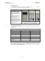
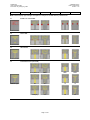
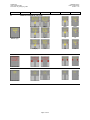
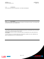
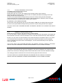
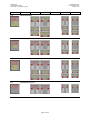
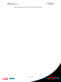
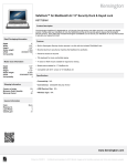
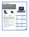
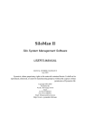
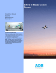
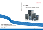
Safedock® User Guide for Pilots Safegate Group Date: 12 April 2012 Version: 1.10 Safedock® User Guide for Pilots Document: SG_SDK_UG_Pilots SAFEDOCK® USER GUIDE FOR PILOTS CONTENTS Section Description Page No. 1. 1.1 1.2 2. 2.1 2.2 2.3 3. 3.1 4. 4.1 4.2 4.3 4.4 4.5 4.6 4.7 4.8 4.9 4.10 4.11 4.12 4.13 4.14 4.15 4.16 4.17 4.18 4.19 4.20 4.21 4.22 4.23 INTRODUCTION ........................................................................................................... 2 SAFEDOCK ...................................................................................................... 2 DOCUMENTATION .......................................................................................... 2 SAFETY INFORMATION .............................................................................................. 3 GENERAL WARNING ...................................................................................... 3 ITEMS TO CHECK BEFORE ENTERING THE STAND AREA ....................... 3 THE SBU MESSAGE ........................................................................................ 3 SAFEDOCK TYPES ...................................................................................................... 4 FUNCTIONS AND OPTIONS ........................................................................... 4 SAFEDOCK PROCEDURES ........................................................................................ 5 START-OF-DOCKING ...................................................................................... 5 CAPTURE ......................................................................................................... 5 TRACKING........................................................................................................ 5 CLOSING RATE ............................................................................................... 5 ALIGNED TO CENTRE (OPTION) ................................................................... 7 SLOW (DECREASE SPEED) ........................................................................... 7 AZIMUTH GUIDANCE (OPTION) ..................................................................... 9 STOP POSITION REACHED ........................................................................... 9 DOCKING COMPLETED .................................................................................. 9 OVERSHOOT ................................................................................................. 11 STOP SHORT ................................................................................................. 11 WAIT ............................................................................................................... 11 SLOW (IN ABNORMAL SITUATIONS)........................................................... 13 AIRCRAFT VERIFICATION FAILURE............................................................ 13 GATE BLOCKED ............................................................................................ 13 VIEW BLOCKED ............................................................................................. 15 SBU STOP ...................................................................................................... 15 TOO FAST ...................................................................................................... 15 EMERGENCY STOP ...................................................................................... 15 CHOCKS ON (OPTION) ................................................................................. 17 ERROR ........................................................................................................... 17 SYSTEM BREAKDOWN................................................................................. 17 POWER FAILURE .......................................................................................... 17 Page 1 of 20 Safegate Group Date: 12 April 2012 Version: 1.10 Safedock® User Guide for Pilots Document: SG_SDK_UG_Pilots 1. 1.1 INTRODUCTION SAFEDOCK The Safedock Advanced-Visual Docking Guidance System (A-VDGS) provides both pilots with guidance for manoeuvring the aircraft into the gate to the correct centreline and stop-position under all operational conditions. A Safedock includes a built-in computer integrated to a low-intensity infrared laser that scans the gate area for the approaching aircraft. Safedock locks onto the aircraft to determine nose, engine, and wing positions to guide it to its park position. During the docking, Safedock also performs a safety check for a positive match of the inbound aircraft type, docking is interrupted if there is a mismatch. Airport operations requirements include an optimum use of existing airport space, management of an ever changing mix of aircraft in airline fleets as well as safety and efficiency. 1.2 DOCUMENTATION This document has been compiled to give the reader a quick understanding of operation procedures, with a focus on safety and efficiency. It is also an overview of the Pilots Display messages that may appear on the most common Safedock Types (T1, T2, T3), installed at numerous airports around the world. The distances are provided in metric (metres) and imperial (feet) values, where 1 metre = 3.3 feet approximately and 1 foot = 0.3 metre approximately. Note: It is recommended to print this information as a double-sided document or as a booklet, to show texts to the left (even page) and images to the right (odd page). For more detailed information, see the Safedock Manual or www.safegate.com. Copyright © Copyright 2012 by Safegate International AB. All rights reserved. This item and the information contained herein are the property of Safegate International AB. No part of this document may be reproduced, transmitted, transcribed, stored in a retrieval system, or translated into any language or computer language in any form or by any means otherwise, without the expressed written permission of Safegate Group, Djurhagegatan 19, SE-213 76 Malmö, Sweden. History Version 1.0 1.1 1.2 1.3 1.4 1.5 1.6 1.7 1.8 1.9 1.10 Date January 2008 July 2008 January 2009 May 2009 September 2009 January 2010 June 2010 November 2010 April 2011 June 2011 April 2012 Description First Release (Single type option) All type options Type options compared General update Feature update Feature update Feature update Minor update Minor update T2, T3 LED update Drawings update Note: This page is to be updated with every authorised change to the document. Page 2 of 20 Safegate Group Date: 12 April 2012 Version: 1.10 Safedock® User Guide for Pilots Document: SG_SDK_UG_Pilots 2. 2.1 SAFETY INFORMATION Safedock Advanced-Visual Docking Guidance System is an aircraft parking aid for airport and aircraft safety and efficiency. The design is according to strict airport industry standards for the safety of, and use by authorised airport personnel. GENERAL WARNING The Safedock has a built-in error detection program to inform the aircraft pilot of impending dangers during the docking procedure. WARNING! IF A PILOT IS UNSURE OF THE INFORMATION BEING SHOWN ON THE SAFEDOCK DISPLAY UNIT, HE MUST IMMEDIATE STOP THE AIRCRAFT AND OBTAIN FURTHER INFORMATION FOR CLEARANCE. 2.2 ITEMS TO CHECK BEFORE ENTERING THE STAND AREA WARNING! A PILOT SHALL NOT ENTER THE STAND AREA, UNLESS THE DOCKING SYSTEM FIRST IS SHOWING THE VERTICAL RUNNING ARROWS. THE PILOT MUST NOT PROCEED BEYOND THE BRIDGE, UNLESS THESE ARROWS HAVE BEEN SUPERSEDED BY THE CLOSING RATE BAR. WARNING! A PILOT SHALL NOT ENTER THE STAND AREA, UNLESS THE AIRCRAFT TYPE DISPLAYED IS EQUAL TO THE APPROACHING AIRCRAFT. THE CORRECTNESS OF OTHER INFORMATION, SUCH AS ‘DOOR 2’, SHALL ALSO BE CHECKED. 2.3 THE SBU MESSAGE The message STOP SBU means that docking has been interrupted and has to be resumed only by manual guidance. DO NOT TRY TO RESUME DOCKING WITHOUT MANUAL GUIDANCE. Note: This information for Pilots must be distributed to all airlines using the systems. Page 3 of 20 Safegate Group Date: 12 April 2012 Version: 1.10 Safedock® User Guide for Pilots Document: SG_SDK_UG_Pilots 3. SAFEDOCK TYPES A Safedock system includes display types T1-XX, T2-XX, T3-XX (T - types), XX – (number of LEDs). Pilots Display (PD) Type 1-42 as Type 2-18 options: Type 3-9 A single cabinet housing a number of units: display (including LEDs), a laser scanner, control and power units. The unit is mounted 4-8 metres above ground and provides multiple functionality, for example clear pilot instructions, accurate aircraft identification and tracking, as well as quick and easy access to this low maintenance unit. FIGURE T1-42, T2-18, T3-9 CAPTURE 3.1 FUNCTIONS AND OPTIONS Each display type also includes functions with more options available for specific site requirements. Functions and Options START-OF-DOCKING DOCKING COMPLETED SBU-STOP CAPTURE OVERSHOOT TOO FAST TRACKING STOP SHORT EMERGENCY STOP CLOSING RATE WAIT CHOCKS ON ALIGNED TO CENTRE ERROR SLOW AIRCRAFT VERIFICATION FAILURE GATE BLOCKED AZIMUTH GUIDANCE* VIEW BLOCKED POWER FAILURE SYSTEM BREAKDOWN STOP POSITION REACHED Note: The symbol * indicates available options. Note: This document includes options for the distance counts available for display types, in metres and feet. Each option is a specific distance count and not intended as a conversion between metres and feet. Page 4 of 20 Safegate Group Date: 12 April 2012 Version: 1.10 Safedock® User Guide for Pilots Document: SG_SDK_UG_Pilots 4. SAFEDOCK PROCEDURES Note: The following functions and/or options are available for Safedock types (Pilots Displays). Safedock types with other configurations may exist as some airports and may therefore differ from the images used in this document. All display images in this document are subject to modification by Safegate Group/Thorn Airfield Lighting. The descriptions that follow correspond to the respective image examples on the opposite/next page. 4.1 START-OF-DOCKING The system is started by pressing one of the aircraft type buttons on the Operator Panel. When the button has been pressed, WAIT will be displayed. 4.2 CAPTURE The floating arrows indicate that the system is activated and in capture mode, searching for an approaching aircraft. It shall be checked that the correct aircraft type is displayed. The lead-in line shall be followed. THE PILOT MUST NOT PROCEED BEYOND THE BRIDGE, UNLESS THE ARROWS HAVE BEEN SUPERSEDED BY THE CLOSING RATE BAR. 4.3 TRACKING When the aircraft has been caught by the laser, the floating arrow is replaced by the yellow centre line indicator. A flashing red arrow indicates the direction to turn. The vertical yellow arrow shows position in relation to the centre line. This indicator gives correct position and azimuth guidance. 4.4 CLOSING RATE The closing rate is the final countdown from a specific distance to the stop position. A yellow vertical closing rate bar/centre line indicator appears with or without a digital countdown, depending on the configuration. The closing rate bar represents the distance from stop, it consists of a number of rows representing for example 0.3 m or 0.6 m per row, depending on the configuration requirements. Each row turns off as the aircraft approaches stop (reducing the length of the bar, bottom upwards) and as the last row turns off, less than the interval for one row remains until STOP appears. A digital countdown (option) shows the distance to stop numerically, for example starting from 9, 12 (40 feet), 15, 20 or 30 m, depending on the configuration requirements. The digital countdown also uses different decrements during the closing rate process. • Metric digital count example Starting with 1 metre decrements from 20 m down to 3 m followed by 0.2 metre decrements from 3.0 down to 0.2 m and then followed by STOP. • Imperial digital count example Starting with 4 feet decrements from 40 ft down to 12 ft followed by 1 foot decrements from 8 ft down to 1 ft and then followed by STOP. The pictures illustrate aircraft in the closing rate distance from stop position, slightly left of the centre line. The red arrow indicates the direction to steer. Note: Some pictures are units with centre line symbol countdown only - no digital count (NDC). Page 5 of 20 Safegate Group Date: 12 April 2012 Version: 1.10 Safedock® User Guide for Pilots Document: SG_SDK_UG_Pilots T1-42 T2-18 T2-24 T3-9 T3-15 Note: Pilots Display figure/image examples are subject to modification by SAFEGATE. 4.1 START-OF-DOCKING 4.2 CAPTURE 4.3 TRACKING 4.4 CLOSING RATE (OPTION) Metres (m) No Digital Count NDC NDC NDC m m m m Feet (ft) ft ft Ft Page 6 of 20 Safegate Group Date: 12 April 2012 Version: 1.10 Safedock® User Guide for Pilots Document: SG_SDK_UG_Pilots 4.5 ALIGNED TO CENTRE (OPTION) The aircraft is at the displayed distance from the stop position. The absence of any direction arrow indicates an aircraft on the centre line. 4.6 SLOW (DECREASE SPEED) Safedock is configured with a slow down active zone (optional distances set from the stop position, standard 6-24 metres) according to an acceptable docking speed (optional max allowed speed, standard 2 m/s). Note: When 2 m/s is rounded down to a single digit, it is approximately 7 km/h, 4 mph or 3 knots. If the aircraft is approaching faster than the accepted speed, the system will show SLOW as a warning to the pilots. Page 7 of 20 Safegate Group Date: 12 April 2012 Version: 1.10 Safedock® User Guide for Pilots Document: SG_SDK_UG_Pilots T1-42 4.5 T2-18 T2S-24 T3-9 T3-15 ALIGNED TO CENTRE (OPTION) Metres (m) 4.6 No Digital Count NDC NDC NDC m m m m Feet (ft) ft ft ft NDC NDC NDC NDC m m ft ft SLOW (DECREASE SPEED) m Page 8 of 20 Safegate Group Date: 12 April 2012 Version: 1.10 Safedock® User Guide for Pilots Document: SG_SDK_UG_Pilots 4.7 AZIMUTH GUIDANCE (OPTION) The aircraft is at the displayed distance from the stop-position. The yellow arrow indicates an aircraft to the right of the centre line, and the red flashing arrow indicates the direction to turn. 4.8 STOP POSITION REACHED When the correct stop-position is reached, the display will show STOP with a red border or with red lights. 4.9 DOCKING COMPLETED When the aircraft has parked, OK will be displayed. Page 9 of 20 Safegate Group Date: 12 April 2012 Version: 1.10 Safedock® User Guide for Pilots Document: SG_SDK_UG_Pilots T1-42 4.7 Metres (m) T2-18 T2S-24 T3-9 T3-15 AZIMUTH GUIDANCE (OPTION) No Digital Count NDC NDC NDC m m m m Feet (ft) ft ft ft 4.8 STOP POSITION REACHED 4.9 DOCKING COMPLETED Page 10 of 20 Safegate Group Date: 12 April 2012 Version: 1.10 Safedock® User Guide for Pilots Document: SG_SDK_UG_Pilots 4.10 OVERSHOOT If the aircraft has overshot the stop-position, TOO FAR will be displayed. 4.11 STOP SHORT If the aircraft is found standing still but has not reached the intended stop position, the message STOP OK will be shown after a pre-configured time. 4.12 WAIT If some object is blocking the view toward the approaching aircraft or the detected aircraft is lost during docking close to STOP, the display will show WAIT. The docking will continue as soon as the blocking object has disappeared or the system detects the aircraft again. THE PILOT MUST NOT PROCEED BEYOND THE BRIDGE, UNLESS THE “WAIT” MESSAGE has BEEN SUPERSEDED BY THE CLOSING RATE BAR. Page 11 of 20 Safegate Group Date: 12 April 2012 Version: 1.10 Safedock® User Guide for Pilots Document: SG_SDK_UG_Pilots T1-42 T2-18 4.10 OVERSHOOT 4.11 STOP SHORT 4.12 WAIT T2S-24 Page 12 of 20 T3-9 T3-15 Safegate Group Date: 12 April 2012 Version: 1.10 Safedock® User Guide for Pilots Document: SG_SDK_UG_Pilots 4.13 SLOW (IN ABNORMAL SITUATIONS) This display can be shown for two reasons: A) BAD WEATHER CONDITION During heavy fog, rain or snow, the visibility for the docking system can be reduced. When the system is activated and in capture mode, the display will disable the floating arrows and display SLOW and the Aircraft Type. As soon as the system detects the approaching aircraft, the vertical closing rate bar will appear. If the system has been configured in this mode to make a shortened ID verification (check of engine position excluded), the Aircraft symbol will blink to give attention. B) AIRCRAFT LOST DURING DOCKING If the aircraft is lost during docking far out from the bridge or PBB area, the display will show SLOW. As soon as the system detects the approaching aircraft, the vertical closing rate bar will re-appear. THE PILOT MUST NOT PROCEED BEYOND THE BRIDGE, UNLESS THE CLOSING RATE BAR IS SHOWN. 4.14 AIRCRAFT VERIFICATION FAILURE During entry into the Stand, the aircraft geometry is being checked. T1: If, for any reason, aircraft verification is not made 12 metres before the stop-position, the display will first show WAIT and make a second verification check. If this fails STOP and ID FAIL will be displayed. T2, T3: If, for any reason, aircraft verification is not made according to the distance option or 12 metres or 40 feet before the stop-position, the display will first show WAIT and make a second verification check. If this fails STOP and ID FAIL will be displayed. The text will be alternating on the upper two rows of the display. THE PILOT MUST NOT PROCEED BEYOND THE BRIDGE WITHOUT MANUAL GUIDANCE, UNLESS THE WAIT MESSAGE HAS BEEN SUPERSEDED BY THE CLOSING RATE BAR. 4.15 GATE BLOCKED If an object is found blocking the approach to gate/apron view from the Safedock to the planned stop position for the aircraft, the docking procedure will be halted with a WAIT and GATE BLOCK message. The docking procedure will resume as soon as the blocking object has been removed. THE PILOT MUST NOT PROCEED BEYOND THE BRIDGE WITHOUT MANUAL GUIDANCE, UNLESS THE WAIT MESSAGE HAS BEEN SUPERSEDED BY THE CLOSING RATE BAR. Page 13 of 20 Safegate Group Date: 12 April 2012 Version: 1.10 Safedock® User Guide for Pilots Document: SG_SDK_UG_Pilots T1-42 T2-18 T2-24 4.13 SLOW (IN ABNORMAL SITUATIONS) 4.14 AIRCRAFT VERIFICATION FAILURE 4.15 GATE BLOCKED Page 14 of 20 T3-9 T3-15 Safegate Group Date: 12 April 2012 Version: 1.10 Safedock® User Guide for Pilots Document: SG_SDK_UG_Pilots 4.16 VIEW BLOCKED If the view towards the approaching aircraft is hindered, for example internally in the unit on the laser lens or on the laser window by dirt, or another obstacle in the closest view area, the Safedock will report a View blocked condition. Once the system is able to see the aircraft through the hinder, the message will be replaced with a closing rate display. THE PILOT MUST NOT PROCEED BEYOND THE BRIDGE WITHOUT MANUAL GUIDANCE, UNLESS THE WAIT MESSAGE HAS BEEN SUPERSEDED BY THE CLOSING RATE BAR. 4.17 SBU STOP Any unrecoverable error during the docking procedure will generate an SBU (safety back-up) condition. The display will show the text STOP SBU. A MANUAL BACKUP PROCEDURE MUST BE USED FOR DOCKING GUIDANCE. 4.18 TOO FAST If the aircraft approaches with a speed higher than the docking system can handle, the message STOP TOO FAST will be displayed. The docking system must be re-started or the docking procedure completed by manual guidance. 4.19 EMERGENCY STOP When the Emergency Stop button is pressed, STOP is displayed. Page 15 of 20 Safegate Group Date: 12 April 2012 Version: 1.10 Safedock® User Guide for Pilots Document: SG_SDK_UG_Pilots T1-42 T2-13 T2-18 4.16 VIEW BLOCKED 4.17 SBU-STOP 4.18 TOO FAST 4.19 EMERGENCY STOP T2S-24 Page 16 of 20 T2S-27 T3-9 T3-15 Safegate Group Date: 12 April 2012 Version: 1.10 Safedock® User Guide for Pilots Document: SG_SDK_UG_Pilots 4.20 CHOCKS ON (OPTION) CHOCK ON will be displayed, when the ground staff has put the chocks in front of the nose wheel and pressed the “Chocks On” button on the Operator Panel. 4.21 ERROR If a system error occurs, the message ERROR is displayed with an error code. The code is used for maintenance purposes and explained elsewhere. 4.22 SYSTEM BREAKDOWN In case of a severe system failure, the display will go black. A manual backup procedure must be used for docking guidance. 4.23 POWER FAILURE In case of a power failure, the display will be completely black. A manual backup procedure must be used for docking guidance. Page 17 of 20 Safegate Group Date: 12 April 2012 Version: 1.10 Safedock® User Guide for Pilots Document: SG_SDK_UG_Pilots T1-42 T2-18 4.20 CHOCKS ON (OPTION) 4.21 ERROR 4.22 SYSTEM BREAKDOWN 4.23 POWER FAILURE T2S-24 Page 18 of 20 T3-9 T3-15 Safegate Group Date: 12 April 2012 Version: 1.10 Safedock® User Guide for Pilots Document: SG_SDK_UG_Pilots Note: This page is blank for convenient double-sided printing. Page 19 of 20 Safegate Group Date: 12 April 2012 Version: 1.10 Safedock® User Guide for Pilots Document: SG_SDK_UG_Pilots Check in to the future How many aircraft can your airport handle today? Can this number be increased without adverse effects on the airport’s safety level? It is a known fact that traffic volume will rise in the foreseeable future. More movements will demand monitoring of the entire airport. Requirements will be sharpened and the development of an integrated system controlling not only ground movements but also air traffic close to the airport is of the highest interest. The International Civil Aviation Organization (ICAO) already describes A-SMGCS, Advanced Surface Movement Guidance and Control System, as the answer to the future modern airport need to control the entire airport space in one superior system. To a larger extent than today’s systems, A-SMGCS will rely on automated processes to give both pilots and traffic controllers exact information about positions and directions. Safegate Group delivers complete A-SMGCS solutions already, as well as all vital parts relating to it. Safegate Group can check your airport into the future – today! Singapore [email protected] +65 6289 6893 Safegate Group HQ Djurhagegatan 19 SE-213 76 Malmö, Sweden Phone: +46 (0)40 699 17 00 Fax: +46 (0)40 699 17 30 E-mail: [email protected] China [email protected] +8610-85275297 France [email protected] +33 (0)1 49 53 62 62 Malaysia [email protected] +60 16 551 7126 Spain [email protected] +34 917 157 598 Dubai [email protected] +971 4 332 30 07 Germany [email protected] +49 (0)231 9776754 Qatar [email protected] +974 436 9628 UK [email protected] +44 (0)208 573 0384 Australia [email protected] +61 (0)3 9720-3233 Finland [email protected] +358 (0)20754 7700 India [email protected] +91 11 4106 1545 Russia [email protected] +7 495 917 4614 USA [email protected] +1 763 535 92 99 Safegate Group offers solutions for increased safety, efficiency and environmental benefits to airports around the world. The company was founded in 1973 and has its headquarters in Malmö, Sweden. Safegate Group has over 70 partners around the globe in order to be close to its customers. The latest members of Safegate Group, Thorn AFL and Idman, have both over 40 years of experience in airfield lighting solutions for airports and heliports worldwide. Safegate Group´s complete range of products and services, a “one-stop shop”, provides solutions to customers and airborne travellers around the globe. Page 20 of 20 For more contact information and details: www.safegate.com