1
Troubleshooting
4. Troubleshooting
4-1 Troubleshooting
4-1-1 First Checklist for Troubleshooting
1. Check the various cable connections first.
- Check to see if there is a burnt or damaged cable.
- Check to see if there is a disconnected or loose cable connection.
- Check to see if the cables are connected according to the connection diagram.
2. Check the power input to the Main Board.
3. Check the voltage in and out between the SMPS ↔ Main Board, between the SMPS ↔ X, Y Main Board, and between the
Logic Boards.
Samsung Electronics
4-1
Troubleshooting
4-1-2 Checkpoints by Error Mode
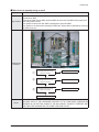
■ No Power
Symptom
- The LEDs on the front panel do not work when connecting the power cord.
- The SMPS relay does not work when connecting the power cord.
- The unit appears to be dead.
The SMPS relay or the LEDs on the front panel does not work when connecting the power cord if the cables
are improperly connected or the Main Board or SMPS is not functioning. In this case, check the following:
- Check the internal cable connection.
Major Checklist
- Check the fuses.
- Check the output voltage of the SMPS.
- Replace the Main Board.
Troubleshooting
Procedures
①
Is the AC IN socket connector and
the SMPS CN800 connected?
No
Insert the AC in connector and the
SMPS CN800 connector
Yes
①
Is the Fuse (F801S) of the SMPS
Power Input Part blown?
Yes
Replace Fuse (F801S)
No
②
SMPS CN801
Pin 3 : STB 5V
Pin 2 PS-ON : Check to see if it is 0V
No
Replace the SMPS
Yes
Replace the Main Board
4-2
Samsung Electronics
Troubleshooting
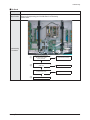
■ When the unit is repeatedly turning on and off
Symptom
- The SMPS relay is repeatedly turning on and off.
In general, the SMPS relay repeatedly turns on and off by the protection function due to a defect on a board
connected to the SMPS.
- Disconnect all cables from the SMPS, operate the SMPS alone and check if the SMPS works properly and if
Major Checklist each voltage output is correct.
- If the symptom continues even when SMPS is operated alone, replace the SMPS.
- If the symptom is not observed when operating the SMPS alone, find any defective assemblies by connecting
the cables one by one.
Troubleshooting
Procedures
①
Does the symptom continue when
connecting the power after removing
CN810 from the SMPS?
No
Replace the Y Main Board
Yes
②
Does the symptom continue when
connecting the power after removing
CN809 from the SMPS?
No
Replace the X Main Board
Yes
③
Does the symptom continue when
connecting the power after removing
CN807 from the SMPS?
No
Replace the Logic Board
Yes
Replace the SMPS
Caution
WHEN SEPARATING AND CONNECTING THE CABLES SUCH AS CN810, CN809, CN808, CN807 OF THE
MAIN SMPS, CN4701 OF THE X MAIN BOARD, AND CN5707 OF THE Y MAIN BOARD, A SPARK MAY BE
GENERATED BY THE ELECTRIC CHARGE OF THE HIGH CAPACITY CAPACITOR. THEREFORE, WAIT
SOME TIME AFTER DISCONNECTING THE POWER CORD FROM THE UNIT.
Samsung Electronics
4-3
Troubleshooting
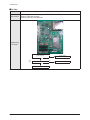
■ No Picture (When audio is normal)
Symptom
- Audio is normal but no picture is displayed on the screen.
- This may happen when the Main Board is functioning but the X, Y Main Board, Logic Board, or Y Buffer
Boards are not.
Major Checklist
- The output voltage of the Main SMPS.
- This may happen when the LVDS cable connecting the Main Board and the Logic Board is disconnected.
CN810
CN809
CN808
CN807
Troubleshooting
Procedures
Are the Vs and Va voltages normal after
removing all cables from the SMPS?
(CN810, CN809, CN808, CN807)
No
Replace the SMPS
Yes
Did problem improve?
No
Replace the Y Main Board
Yes
Did problem improve?
No
Replace the X Main Board
Yes
Did problem improve?
No
Replace the Logic Board
Yes
Did problem improve?
Caution
4-4
No
Replace the Y Scan Board
WHEN SEPARATING AND CONNECTING THE CABLES SUCH AS CN810, CN809, CN808, CN807 OF THE
MAIN SMPS, CN4701 OF THE X MAIN BOARD, AND CN5707 OF THE Y MAIN BOARD, A SPARK MAY BE
GENERATED BY THE ELECTRIC CHARGE OF THE HIGH CAPACITY CAPACITOR. THEREFORE, WAIT
SOME TIME AFTER DISCONNECTING THE POWER CORD FROM THE UNIT.
Samsung Electronics
Troubleshooting
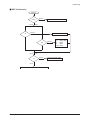
■ No Sound
Symptom
- Video is normal but there is no sound.
- When the speaker connectors are disconnected or damaged.
Major Checklist - When the sound processing part of the Main Board is not functioning.
- Speaker defect.
Troubleshooting
Procedures
①
Is the cable connection between the
Main Board and the speaker
properly connected?
No
Connect the cable properly or
replace the cable, if necessary.
Yes
②
Is the output voltage of SMPS normal?
(CN801 #13)
No
Replace the SMPS
Yes
Is the speaker output terminal
of the Main Board normal?
No
Replace the Main Board
Yes
③
Samsung Electronics
Replace the Speaker
4-5
Troubleshooting
■ No Video
Symptom
- A normal/cable network analog broadcast screen is blank or abnormal but OSD is OK.
- Check the antenna connection settings (Air: NTSC / ATSC, Cable: NTSC)
Major Checklist - Check the CVBS cable connection.
- Check the power input of the Main board.
Troubleshooting
Procedures
Is the antenna connection setting
properly configured?
No
Configure properly
Yes
①
Check CN1101 pin2 for +33V
No
Replace the SMPS
Yes
Replace the Main Board
4-6
Samsung Electronics
Troubleshooting
■ SMPS Troubleshooting
Power ON
STD_5V
Normal
VA
Abnormal
Check the ICB802, DB864, FB801, F801S
PS-ON
Abnormal
Check the SUB2, QX801,QX802
Abnormal
Multi
Normal
Check the
5.3V : ICX808, QX806
12V
: ICX803
VG
: ICX805
18Vamp : ICX804
VS-ON
VS
Abnormal
Check the SUB1,QS801,QS802
Normal
Check the Other board (Image Board or Driver Board) or Cable.
Samsung Electronics
4-7
Troubleshooting
■ Drive Board Troubleshooting
1) Troubleshooting Summary
Condition Name
Description
Related Board
No Voltage Output
Operating Voltage don't exist
PSU
No Display
Operating Voltage exist, but an Image doesn't exist on screen
Y-MAIN, X-MAIN, Logic Main, Cable
Abnormal Display
Abnormal Image (not open or short) is no screen
Y-MAIN, X-MAIN, Logic Main
Sustain Open
Some horizontal lines don't exist on screen
Scan Buffer, FPC of X/Y
Sustain Short
Some horizontal lines appear to be linked on screen
Scan Buffer, FPC of X/Y
Address Open
Some vertical lines don't exist on screen
Logic Main, Logic Buffer, TCP
Address Short
Some vertical lines appear to be linked on screen
Logic Main, Logic Buffer, TCP
4-8
Samsung Electronics
Troubleshooting
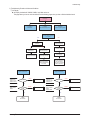
2) Troubleshooting Procedure in Abnormal Conditions
① No Display
▶ No Display is related with Y-MAIN, X-MAIN, Logic Main and so on.
This page shows you how to check the boards, and the following pages show you how to find the defective board.
No Display
[ Logic Main ]
LED Blinks
[ Y-MAIN ]
Check necessary points
[ X-MAIN ]
Check necessary points
[ Logic Main ]
Check if power is supplied
( 5V, 3.3V )
YES
NO
Check the
power connectivity
Check the LED
operation
YES
NO
Check if internal is
Default Black
Check the
MICOM operation
Check if any address
data output is detected
Check the ASIC
Control Signal output
Check if the data
and control signals
between DDR & ASIC
are normal
OPEN
FUSE
Replace the Board
F4001 for VCC
F4002 for Vs
F4004 for VDD
F4005 for Ve
OK
Q5009~Q5021
D5005, D5007
D5008
FET/
DIODE
OK
Y-MAIN
Normal State
Samsung Electronics
Check the
input voltage
If the input voltage is
abnormal, replace the
PSU and check it
again as this indicates
a PSU output error
[ X-MAIN ]
Check several points
[ Y-MAIN ]
Check several points
F5001 for VDD
F5002 for Vs
F5004 for VCC
F5005 for OUT_L
Check the FUSE
OPEN
FUSE
Replace the Board
OK
SHORT
Replace the Board
Q4002~Q4003
Q4011~Q4016
D4004
D4006~D4008
FET/
DIODE
SHORT
Replace the Board
OK
X-MAIN
Normal State
4-9
Troubleshooting
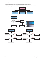
② Abnormal Display(Abnormal Image is on Screen.(except abnormality in Sustain or Address))
▶ Abnormal Display is related with Y-MAIN, X-MAIN, Logic Main and so on.
This page shows you how to check the boards, and the following pages show you how to find the defective board.
Abnormal
Display
[ Logic Main ]
Observation of
abnormal display
[ Y-MAIN ]
Check necessary points
[ X-MAIN ]
Check necessary points
[ Logic Main ]
LED Blinks
( action of Vsync )
Regular
abnormal
pattern
NO
Logic Main
Normal State
YES
Replace the Board
Replace Panel
[ Y-MAIN ]
Check several points
F5001 for VDD
F5002 for Vs
F5004 for VCC
F5005 for OUT_L
[ X-MAIN ]
Check several points
OPEN
FUSE
Replace the Board
F4001 for VCC
F4002 for Vs
F4004 for VDD
F4005 for Ve
OPEN
FUSE
OK
OK
SHORT
Q5009~Q5021
FET
Replace the Board
OK
Y-MAIN
Normal State
4-10
Replace the Board
Q4002~Q4003
Q4011~Q4016
SHORT
FET
Replace the Board
OK
X-MAIN
Normal State
Samsung Electronics
Troubleshooting
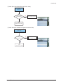
③ Sustain Open (some horizontal lines don't exist on screen)
[ Y-FPC ]
Sustain Open
After Changing Y-buffer,
recheck the status
NG
Replace the Panel
There is a defect on the FPC
OK
Done
(Defect is from Y-buffer)
④ Sustain Short (some horizontal lines appear to be linked on Video)
[ Y-FPC ]
Sustain Short
(Discharging in unwanted Scan line)
After Changing Y-buffer,
recheck the status
NG
Replace the Panel
There is a defect on the FPC
OK
Done
(Defect is from Y-buffer)
Samsung Electronics
4-11
Troubleshooting
⑤ Address Open, Short
▶ Address Open and Short is related with Logic Main, Logic Buffer, FFC, TCP film and so on.
This page shows you how to check the boards, and the following pages show you how to find the defective board.
[ Logic Main ]
Address Open/Short
Check the LED operation
LED2011 : blink
LED2010 : on
Check if the internal mode
screen is normal
NG
NG
Check the
Video Board
OK
check the voltage of
C2901, C2902, C2903 is 1.25V
OK
OK
NG
Reload the data onto the
MICOM and recheck it
Check if a specific TCP Block
screen is displayed abnormally
OK
check the voltage of
U2650 pin1 is 3.3V
Check if there is an open or
short circuit on the Buffer Board
and the Logic Main address
data output section.
Check the FFC connection status
NG
NG
Check the detailed waveform
and control the signal waveform
Replace Logic Main /
Address Buffer (E or F) /
FFC
OK
DONE
4-12
NG
Replace the Panel
Samsung Electronics
Troubleshooting
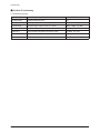
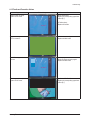
4-1-3 Faults and Corrective Actions
Symptom
A blank vertical cell (block)
appears on the screen.
Related Image
Causes and Countermeasures
Address buffer defect
- Replace the corresponding upper/lower
buffers (E, F)
COF defect (burnt)
- Replace the module
A green screen appears when
the TV is turned on.
The Scale is not reseting
- Replace the Main board
The OSD box appears but there
is no text.
Incorrect program version
- Check the version of each program
- Replace the Main board
A blank upper (or lower) block
appears on the screen.
Upper/Lower Y Buffer defect
- Replace the corresponding upper/lower
buffers (E, F)
Samsung Electronics
4-13
Troubleshooting
Symptom
Related Image
Causes and Countermeasures
Either the main or sub picture
does not appear.
Replace the Main board
A vertical green line appears on
the screen.
The SMPS voltage is incorrect
- Adjust the SMPS voltage according to
the voltage printed on the module label
Dim screen (blurred in red)
X-Main board defect
- Replace the X-Main board
A blank screen appears
- Replace the Y-Main board
4-14
Samsung Electronics
Troubleshooting
4-1-4 Troubleshooting Procedures by assembly
No
Assembly
Major Symptoms
1
SMPS-PDP TV
No power, Blank screen, the Relay repeats On and Off.
2
ASSY PDP MODULE P-X-MAIN
Blank screen
3
ASSY PDP MODULE P-Y-MAIN
Blank screen
4
ASSY PDP MODULE P-LOGIC MAIN
Blank screen, Screen noise
5
ASSY PDP MODULE P-Y-MAIN SCAN BUFFER
Row Bar screen is blank
6
ASSY PDP MODULE P-ADDRESS E BUFFER
Corresponding Buffer Board block screen is blank.
7
ASSY PDP MODULE P-ADDRESS F BUFFER
Corresponding Buffer Board block screen is blank.
8
ASSY PCB MISC-MAIN
No Power, Abnormal screen for each input source, PIP screen trouble, Sound trouble
9
ASSY BOARD P-FUNCTION
The side function key does not work properly
10 ASSY BOARD P-POWER&IR
The remote control does not work properly, the LED does not work properly.
11 ASSY BOARD P-SIDE AV
The AV2 and S-VIDEO2 modes do not work properly
<PDP 42”>
Samsung Electronics
<PDP 50”>
4-15
Troubleshooting
4-2 Adjustment
4-2-1 Service Instruction
■ Before Performing After Sales Services
1. Check if the measurement and test equipment is working properly.
2. Secure sufficient work space for disassembling the product.
3. Prepare a soft pad for disassembling the product.
■ Service adjustment item after replacement of Board
<If adjustment equipment is available>
① PDP Option of Factory Mode → set the Factory Data Type item as the suitable value of relevant model.
② Adjust Calibration of Factory Mode for each mode.
③ Adjust White Balance of Factory Mode.
<If adjustment equipment is not available>
① Write down the value of HDMI White Balance of Factory Mode before replacing Board.
② PDP Option of Factory Mode → set the Factory Data Type item as the suitable value of relevant model.
③ Set the value of HDMI White Balance with the value written down before.
4-16
Samsung Electronics
Troubleshooting
4-2-2 How to Access Service Mode
1. General Remote
To Enter: POWER OFF → INFO → MENU → MUTE → POWER ON
(Interval between key strokes: less than 3 sec)
To Exit:
POWER OFF → POWER ON
2. Factory Remote
To Enter: POWER ON → INFO → FACTORY
→ Key
To Exit:
(Interval between key strokes: less than 3 sec)
POWER OFF → POWER ON
Press the Factory key twice with a key stroke interval of more than 1 second (Pressing once enters Aging Mode)
3. Settings when entering Factory mode
- Sharp Screen (Dynamic), Color Tone (Cool1), Factory (Dynamic CE Off)
4. Adjustment Procedures
- Channel ▲ ▼ Key : Select an item.
- Volume ◀▶ Key : Adjust the value up or down.
- MENU Key
: Save the changes to the EEPROM and return to the higher-level mode.
- Using the Numeric (0~9) keys, you can select a channel.
- Using the SOURCE key, you can switch AV modes.
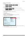
5. Initial SERVICE MODE DISPLAY State
Panel ON Time(Hour) 0002
1. Calibration
2. Option Table
3. White Balance
4. SVP-UX
5. Option Block
6. SGTV5810/NTP3000
C4A_RMA
7. YC Delay
8. Adjust
9. I2C Check
10. W/B MOVIE
11. Checksum
12. Reset
13. Spread Specturm
50": C5A_RMA
T-CALMPEUH-xxxx (Main Micom Ver)
T-BDPMPEUS-xxxx
BORD2_CALLA_TR-xxxx (TR Ver)
Month / Day / Year / Hour / Min. / Sec.
※ The version of the firmware displayed at the bottom of the screen may differ and the firmware is subject to change for the
improvement of product functions.
※ If you have adjusted the settings in Service Mode, you have to reset the product.
Samsung Electronics
4-17
Troubleshooting
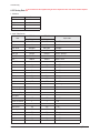
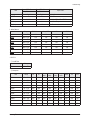
4-2-3 Factory Data
★ The underlined are items applied during the service adjustment. None of the others should be adjusted.
1. Calibration
Item
Data
AV Calibration
Success
Comp Calibration
Success
PC Calibration
Success
HDMI Calibration
Success
2. Option Table(Service)
Item
PDP 42"
PDP 50"
Option index
C4A_RMA initial value C5A_RMA initial value
Ready
OFF
OFF
ON / OFF
Inch Option
42"
50"
42" / 50"...
AMLCDINT
AMLCDINT
OFF
OFF
Panel Type
Normal1
Normal1
Normal1 / Normal2...
Model Option
Bord Plus
Bord Plus
Call / Lily / Brod Plus / Jasmine
Tuner
SEMCO
SEMCO
SEMCO / ALPS
Tuner TOP
8
8
Auto Power
ON
ON
ON / OFF
Nordic
OFF
OFF
ON / OFF
LNA Menu
ON
ON
ON / OFF
TTX On/Off
ON
ON
ON / OFF
TTX List
Flof
Flof
Flof / List
Carrier Mute
OFF
OFF
ON / OFF
High Deviation
OFF
OFF
ON / OFF
VOL.Curve
Small
Small
Small / Large
HDMI Hotplug
1
1
0/1
HDMI Clock CtrI
1
1
0/1
HDMI Hotplug Dly
9
9
3~50
OFF
OFF
Power On Channel
1
1
1 ~ 99
Power On Volume
10
10
1 ~ 100
Max Volume
100
100
1 ~ 100
Local Key Lock
OFF
OFF
ON / OFF
Power On Source
RF
RF
RF/Ext.1...
Shop Mode
OFF
OFF
ON / OFF
Color Space
ON
ON
ON / OFF
PC Ident
OFF
OFF
ON / OFF
Panel Vender
Gamma
AUO/CMO...
ON / OFF
0 ~ 31
Hotel Option
Hotel Mode
4-18
ON / OFF
Samsung Electronics
Troubleshooting
Item
PDP 42"
PDP 50"
Option index
C4A_RMA initial value C5A_RMA initial value
Language
English
English
English / German...
ANYNET+
ON
ON
Ch.Table
SUWON
SUWON
TTX Group
Auto
Auto
Auto / West Europe...
iDTV_Cntry
UK
UK
UK / France...
ON / OFF
SUWON / SESK / SEH / TTSEC
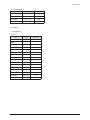
3. White Balance
Item
Range
Tv/AV/Scart
Comp/iDTV
PC
HDMI
Sub-Briteness
00H ~ FFH
128
128
128
128
R-offset
00H ~ FFH
128
128
128
128
G-offset
00H ~ FFH
128
128
128
128
B-offset
00H ~ FFH
128
128
128
128
Sub-Contrast
00H ~ FFH
128
128
128
128
R-Gain
00H ~ FFH
128
128
128
128
G-Gain
00H ~ FFH
128
128
128
128
B-Gain
00H ~ FFH
128
128
128
128
4. SVP-UX
① ComB Filter
Item
Y-Filter
Range
00H ~ FFH
② Sharpness
Range
RF
AV
Comp
480i
Comp
480p
Comp
720p
Comp
1080i
HDMI
PC
iDTV
H2Gain
00 ~ 1FH
05H
05H
05H
05H
04H
04H
0AH
05H
05H
H4Gain
00 ~ 1FH
04H
0AH
05H
05H
02H
02H
0AH
05H
05H
V2Gain
00 ~ 1FH
0CH
0CH
0AH
0CH
0AH
0AH
10H
0AH
0AH
V4Gain
00 ~ 1FH
0CH
10H
0CH
0CH
0AH
0AH
10H
0AH
0AH
Sr2Gain
00 ~ 1FH
00H
00H
00H
00H
00H
00H
00H
00H
00H
Sr4Gain
00 ~ 1FH
00H
02H
00H
00H
02H
02H
04H
02H
02H
Sl2Gain
00 ~ 1FH
00H
00H
00H
00H
00H
00H
00H
00H
00H
Sl4Gain
00 ~ 1FH
00H
02H
00H
00H
02H
02H
04H
02H
02H
Peakth1
00H ~ FFH
06H
02H
03H
03H
03H
03H
03H
08H
04H
Peakth2
00H ~ FFH
2FH
2FH
2FH
2FH
2FH
2FH
2FH
2FH
2FH
Peskth3
00H ~ FFH
3FH
3FH
3FH
3FH
3FH
3FH
3FH
3FH
3FH
Item
Samsung Electronics
4-19
Troubleshooting
③ NR
Item
Range
Initial value
Y_NR_OFF
00H ~ FFH
00H
C_NR_OFF
00H ~ FFH
00H
Y_NR_ON
00H ~ FFH
00H
C_NR_ON
00H ~ FFH
00H
Range
TV/AV/S_Video
Component
PC
HDMI
R-Offset
00H ~ FFH
3AH
40H
32H
82H
G-Offset
00H ~ FFH
3AH
40H
32H
82H
B-Offet
00H ~ FFH
3AH
40H
32H
82H
R-Gain
00H ~ FFH
A6H
92H
A9H
6CH
G-Gain
00H ~ FFH
A6H
92H
A9H
6CH
B-Gain
00H ~ FFH
A6H
92H
A9H
6CH
Range
TV/AV/S_Video
Component
PC
HDMI
TCD3 Contrast
00H ~ FFH
79H
78H
78H
78H
TCD3 Brightness
00H ~ FFH
29H
20H
20H
20H
TCD3 CR
00H ~ FFH
80H
80H
80H
80H
TCD3 CB
00H ~ FFH
80H
80H
80H
80H
TCD3 Delay
00H ~ FFH
00H
00H
00H
00H
Analog Y Offset
00H ~ FFH
40H
3DH
44H
40H
Analog PB Offset
00H ~ FFH
80H
80H
44H
80H
Analog PR Offset
00H ~ FFH
80H
80H
44H
80H
Analog Y Gain
00H ~ FFH
D6H
B3H
A4H
80H
Analog PB Gain
00H ~ FFH
80H
B3H
ACH
80H
Analog PR Gain
00H ~ FFH
80H
B3H
A7H
80H
Black Level
00H ~ FFH
00H
00H
00H
00H
Svp Brightness
00H ~ FFH
00H
00H
00H
00H
Range
low
high
Delta
AV ADC
00H ~ FFH
10H
DCH
02H
COMP ADC
00H ~ FFH
10H
EBH
02H
PC ADC
00H ~ FFH
10H
DCH
04H
ALL RGB
00H ~ FFH
01H
EBH
0AH
④ RGB Calibration
Item
⑤ ADC Calibration
Item
⑥ Calibration Target
Item
4-20
Samsung Electronics
Troubleshooting
⑦ Color Management
Item
Range
Initial value
Skin Direction
Reddish / Yellowish
Reddish
Skin Enhance
00H ~ FFH
00H
Green Stretch
00H ~ FFH
00H
Blue Stretch
00H ~ FFH
00H
5. Option Block
① FRC(Micronas)
② FRC2X
Item
Range
Initial value
OUTCON
1~3
0
GAMMA
1~7
0
OCC_MODE
0/1
0
FALLBACK
0/1
0
DBG_MARK
0/1
0
SPR_CBR
0/1
0
BIT_EXPAND
0/1
0
INV_BIT_EXPAND
0/1
0
REPEAT_MODE
0/1
0
DEMO_ON_OFF
0/1
0
MMU_RD_START
00H ~ FFH
00H
ME_RD_START
00H ~ FFH
00H
MC_RD_START
00H ~ FFH
00H
CMZL(0x36E)
00H ~ FFH
0H
BLOL(0x2A7)
00H ~ FFH
0H
LOGO(0x2A7)
00H ~ FFH
0H
Samsung Electronics
4-21
Troubleshooting
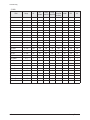
③ FBE2
Comp
Comp
Comp
720p/108
480i/576i 480p/576p
0i/1080p
ITEM
Range
RF
AV/
S-Video
Pattern Select
0 ~ 20
0
0
0
0
0/1
1
1
1
B-Slope Gain
0 ~ 255
34
44
B-Tilt Min
0 ~ 255
20
B-Tilt Max
0 ~ 255
B-Tilt Slope
HDMI
DTV
PC
0
0
0
0
1
1
1
1
1
64
64
64
64
64
64
20
20
20
20
20
20
20
120
120
120
120
120
120
120
120
0 ~ 255
128
128
128
128
128
128
128
128
LFunc-Basis
0 ~ 255
30
20
50
40
70
55
75
55
Hfunc-Basis
0 ~ 255
30
40
50
40
75
65
88
65
Mean-Offset1
0 ~ 255
20
100
75
75
75
75
75
75
Mean Offset2
0 ~ 255
120
200
155
155
225
225
225
225
Mean Slope
0 ~ 255
56
56
45
45
85
85
85
85
Input Offset
0 ~ 255
128
128
128
128
128
128
128
128
Input Gain
0 ~ 255
128
128
128
128
128
128
128
128
ACR Offset
0 ~ 128
15
15
15
15
15
15
15
15
ACR Th1
0 ~ 255
30
30
30
30
30
30
30
30
ARC Th2
0 ~ 255
130
130
100
130
130
130
130
130
0/1
1
1
1
1
1
1
1
1
Skin Tu
0 ~ 255
165
165
150
150
165
165
128
165
Skin Tv
0 ~ 255
140
140
140
140
128
128
128
128
M Skin Tu
0 ~ 255
128
128
128
128
128
128
128
128
M Skin TV
0 ~ 255
128
128
128
128
128
128
128
128
Sub Color
0 ~ 255
115
128
135
135
140
150
143
150
M-Au-Sub Color
0 ~ 255
128
128
128
128
128
128
128
128
M-Wi-Sub Color
0 ~ 255
128
128
128
128
128
128
128
128
MW-Skin-Tu
0 ~ 255
128
128
128
128
128
128
128
128
MW-Skin-Tv
0 ~ 255
128
128
128
128
128
128
128
128
BS-On
Skin Enable
4-22
Samsung Electronics
Troubleshooting
④ Pdp Logic
ITEM
Range
Initial value
Pattern Srlect
0 ~ 63
0
Data updata
ON / OFF
OFF
Data Type
42"EU MRT/42"EU MESH/...
42"EU MRT
CDC Sw
ON / OFF
OFF
0 ~ 31
0
BRE Sw
ON / OFF
OFF
FRC Repeat Mode
ON / OFF
OFF
FRC CBG Mark On
0 ~ 15
0
ERC Bypass
ON / OFF
OFF
Panel Type
-
0H
Panel Inch
-
SD
Panel Version
-
Logic Sw Version
-
CDC Strengh Th
0H 0H 0H
6. SGTV5810/NTP3000
ITEM
Range
Initial value
1H ~ FH
01H
ID Tone Thresh
00H ~ FFH
7FH
Demod Prescaler
00H ~ 20H
13H
Master Volume
00H ~ 30H
13H
PWM Modulation
80H ~ F2H
F1H
DRC Threshold
00H ~ 7FH
06H
Speaker EQ
ON / OFF
OFF
Range
Initial value
RF PAL-B/G
00H ~ FFH
AAH
RF PAL-D/K
00H ~ FFH
99H
RF PAL-I
00H ~ FFH
99H
RF SECAM-B/G
00H ~ FFH
88H
RF SECAM-D/K
00H ~ FFH
44H
RF SECAM-L/L'
00H ~ FFH
88H
RF NTSC 3.58
00H ~ FFH
44H
RF NTSC 4.43
00H ~ FFH
CCH
AV PAL
00H ~ FFH
AAH
AV SECAM
00H ~ FFH
88H
AV NTSC 3.58
00H ~ FFH
30H
AV NTSC 4.43
00H ~ FFH
AAH
AV PAL60
00H ~ FFH
77H
ID Tone Shift
7. YC Delay
ITEM
Samsung Electronics
4-23
Troubleshooting
8. Adjust
ITEM
Range
Initial value
Video Mute Time
0 ~ 255
10
Dynamic Contrast
ON / OFF
ON
Dynamic Dimming
ON / OFF
ON
Dynamic CE
ON / OFF
OFF
RFDB-1 Level
0 ~ 255
2
RFDB-2 Level
0 ~ 255
5
RFDB-3 Level
0 ~ 255
7
RFDB-4 Level
0 ~ 255
24
Magazine LNA
ON / OFF
OFF
PixelShift Test
ON / OFF
OFF
Debug
ON / OFF
OFF
ACR
ON / OFF
OFF
D-Watchdog
ON / OFF
ON
UART Select
MAIN / IDTV / PDP Lvds ON
/ PDP Lvds /OFF
OFF
LNA PLUS
9. I2C Check
4-24
Samsung Electronics
Troubleshooting
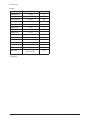
10. W/B MOVIE
ITEM
Range
TV/AV/S_Video
Component
PC
HDMI
Scart1/2
WB Movie
ON / OFF
OFF
OFF
OFF
OFF
OFF
Color Mode
Movie
Movie
Dynamic
Dynamic
Dynamic
Dynamic
Cool1
Cool1
Cool1
Cool1
Cool1
Color Tone
Msub Brigh
0 ~ 255
128
128
128
128
128
Msub Contr
0 ~ 255
128
128
128
128
128
W1_RGAIN
0 ~ 255
157
161
144
161
157
W1_BGAIN
0 ~ 255
76
74
117
76
76
W1_R_OFFS
0 ~ 255
119
119
127
118
119
W1_B_OFFS
0 ~ 255
138
140
110
141
138
W2_RGAIN
0 ~ 255
142
143
149
142
142
W2_BGAIN
0 ~ 255
48
47
93
51
48
W2_R_OFFS
0 ~ 255
129
127
124
128
129
W2_B_OFFS
0 ~ 255
143
145
110
143
143
NO_RGAIN
0 ~ 255
141
139
137
141
141
NO_BGAIN
0 ~ 255
104
102
123
104
104
NO_R_OFFS
0 ~ 255
126
125
126
121
126
NO_B_OFFS
0 ~ 255
136
133
114
133
136
C2_RGAIN
0 ~ 255
124
122
123
125
124
C2_BGAIN
0 ~ 255
142
141
156
143
142
C2_R_OFFS
0 ~ 255
128
129
117
128
128
C2_B_OFFS
0 ~ 255
128
127
116
128
128
Movie Contr
0 ~ 100
100
100
100
100
100
Movie Brigh
0 ~ 100
45
45
45
45
45
Movie Color
0 ~ 100
55
55
55
55
55
Movie Sharp
0 ~ 100
75
75
75
75
75
Range
Initial value
ON / OFF
ON
-128 ~ +128
0
Positive
0 ~ 99
8
Negative
0 ~ 99
2
Speed
0~7
0
Time
0~7
4
ON / OFF
OFF
0~5
0
11. Checksum
xxxx
12. Reset
13. Spread Spectrun
ITEM
Spectrum
Delta
FBE Spectrum
FEE Delta
Samsung Electronics
4-25
Troubleshooting
4-2-4 Service Adjustment
■ White Balance - Calibration
If picture color is wrong, do calibration first.
Execute calibration in Factory Mode
1. Source
: VIDEO
2. Setting Mode : PAL Video (MODE : #2)
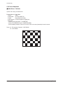
3. Pattern
: Pattern #24 (Chess Pattern)
4. Use Equipment : K-7256 or Equipment of equality level
5. Work order
1) Enter by Factory Mode select "1. CALIBRATION".
2) Select "AV CALIBRATION" again in CALIBRATION MENU.
3) After Completing Calibration, come out "Av success". OSD on the screen (bottom-side) for about 3 seconds.
Source AV : PAL composite, Component : 1280*720/60Hz
PC : 1024*768/60Hz
( Chess Pattern )
4-26
Samsung Electronics
Troubleshooting
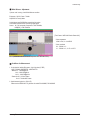
■ White Balance - Adjustment
If picture color is wrong, check White Balance condition.
Equipment : CA210, Patten : Toshiba
Adjust W/B in Factory Mode
Sub brightness and R/G/B Offset controls low light region
Sub contrast and R/G/B Gain controls high light region
Source AV : PAL composite, Component : 1280*720/60Hz,
HDMI[DVI] : 1280*720/60Hz
[ Test Pattern : MSPG-945 Series Pattern #16 ]
* Color temperature
1500K +/-500, -6 ~-20 MPCD
* Color coordinate
H/L : 270/280 +/- 2
L/L : 270/280 +/- 3, 2.1 Ft +/-0.05 Ft
( SAMSUNG WHITE BALANCE Adjustment PATTERN with FPD )
■ Conditions for Measurement
1. On the basis of toshiba ABL pattern : High Light level (57 IRE)
- INPUT SIGNAL GENERATOR : MSPG-925LTH
* Mode No 2 : 744X484@60 Hz
No 6 : 1280X720@60 Hz
No 21 : 1024X768@60 Hz
* Pattern No 36 : 16 Color Pattern
No 16 : Toshiba ABL Pattern
2. Optical measuring device : CA210 (FL)
Please use the MSPG-925 LTH generator for model PS-42Q96HD, PS-50Q96HD.
Samsung Electronics
4-27
Troubleshooting
■ Method of Adjustment
1. Adjust the white balance of AV, Component and DVI Modes.
(AV → Component)
a) Set the input to the mode in which the adjustment will be made (RF → DTV → PC → DVI).
* Input signal - VIDEO Mode : Model #2 (744*484 Mode), Pattern #16
- DTV, DVI Mode : Model #6 (1280*720 Mode), Pattern #16
- HDMI Mode : Model #6 (1280*720 Mode), Pattern #16
b) Enter factory color control, confirm the data.
c) Adjust the low light. (Refer to table 1, 2 in adjustment position by mode)
- Adjust sub - Brightness to set the 'Y' value.
- Adjust red offset ('x') and blue offset ('y') to the color coordinates.
Low light
Measurement point
( SAMSUNG WHITE BALANCE Adjustment PATTERN with FPD )
* Do not adjust green offset data.
d) Adjust the high light. (Refer to table 1, 2 in adjustment position by mode)
- Adjust red gain ('x') and blue gain ('y') to the color coordinates.
Hight light
Measurement point
( SAMSUNG WHITE BALANCE Adjustment PATTERN with FPD )
* Do not adjust the green gain and sub-contrast (Y) data.
4-28
Samsung Electronics
Troubleshooting
4-2-5 Replacements & Calibration
* PDP 42" Check items listed after changing each
Replaced assembly items
Check Items
ASSY PCB MISC-MAIN
1) Auto Program
2) White Balance Adjust
SMPS-PDP TV
Vs, Va voltage check and adjust
ASSY PDP MODULE P-LOGIC MAIN
ASSY PDP MODULE P-X-MAIN
ASSY PDP MODULE P-Y-MAIN
ASSY PDP MODULE P-Y-MAIN SCAN BUFFER
Not to be adjusted
ASSY PDP MODULE P-ADDRESS E BUFFER
ASSY PDP MODULE P-ADDRESS F BUFFER
ASSY BOARD P-SIDE A/V
* PDP 50" Check items listed after changing each
Replaced assembly items
Check Items
ASSY PCB MISC-MAIN
1) Auto Program
2) White Balance Adjust
SMPS-PDP TV
Vs, Va voltage check and adjust
ASSY PDP MODULE P-LOGIC MAIN
ASSY PDP MODULE P-X-MAIN
ASSY PDP MODULE P-Y-MAIN
ASSY PDP MODULE P-Y-MAIN SCAN BUFFER
ASSY PDP MODULE P-Y-MAIN SCAN BUFFER
Not to be adjusted
ASSY PDP MODULE P-ADDRESS E BUFFER
ASSY PDP MODULE P-ADDRESS F BUFFER
ASSY BOARD P-SIDE A/V
※ When replacing the SMPS or PDP panel, you have to check the voltage printed on the panel sticker and adjust it.
Samsung Electronics
4-29
Troubleshooting
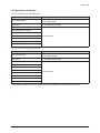
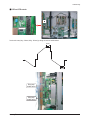
■ Voltage Adjustment
1. After replacing the SMPS or PDP panel, you must adjust the voltage referring to the voltage label printed on the panel.
(If you do not adjust the voltage, an abnormal discharge symptom may appear.)
Value
Vs
210
Va
63
Vset
-
Ve
94
Vscan
-190
Board Adjustment
SMPS
SMPS
Voltage Label
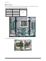
2. A point of adjusting SMPS-MAIN voltage.
Vs Adjustment
Vs Test point
Va Test point
4-30
Va Adjustment
Samsung Electronics
Troubleshooting
■ Y-RR and Y-FR controls
Test Point
Set the main reset (rising : 60usec, falling : 80usec) by change the value of variable resistor.
60usec
80usec
Rising ramp
variable resistor
Falling ramp
variable resistor
Samsung Electronics
4-31
Troubleshooting
4-3 Upgrade
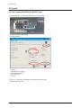
4-3-1 How to Update Flash ROM (with RS-232C Cable)
1. Connect Set (Service Jack) and Jig Cable to execute Program Update.
2. Turn Off (On Stand by mode) the Set
- Run Down load tool
1) Check ①
2) Select MOT file by Open ②
3) Click Connect Button ③
4) Turn On the Set
5) Click ④
3. Turn off (= AC Power off) the Set (waiting a few seconds) and turn on again.
S/W Down Load Time: 6min
4-32
Samsung Electronics
Troubleshooting
4-3-2 How to Check the Version of the Program
1. Procedures for checking in the Factory Menu.
When entering Factory Mode, the version of the software is displayed at the bottom of the menu as described on page 4-17.
Panel ON Time(Hour) 0002
1. Calibration
2. Option Table
3. White Balance
4. SVP-UX
5. Option Block
6. SGTV5810/NTP3000
C4A_RMA
7. YC Delay
8. Adjust
9. I2C Check
10. W/B MOVIE
11. Checksum
12. Reset
13. Spread Specturm
T-CALMPEUH-xxxx (Main Micom Ver)
T-BDPMPEUS-xxxx
BORD2_CALLA_TR-xxxx (TR Ver)
Month / Day / Year / Hour / Min. / Sec.
Samsung Electronics
S/W Version
4-33