1
Edition: 12.2009 · 610.44520.40.000
Original operating instructions · English
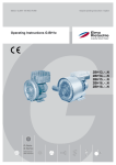
Operating Instructions G-BH7e
2BH72..-..N
2BH73..-..N
2BH74..-..N
2BH75..-..N
2BH76..-..N
G-Serie
G-Series
Seitenkanal
Side Channel
Contents
Contents
Design of side channel blowers in conjunction with frequency inverters ........................................... 3
Quick start guide ................................................................................................................................ 4
1 Safety instructions ...............................................................................................................................5
1.1 Definitions .................................................................................................................................5
1.1.1 Safety alert symbols and signal words.........................................................................5
1.1.2 Signal words.................................................................................................................5
1.1.3 Abbreviations used.......................................................................................................5
1.2 General safety and application notes........................................................................................5
1.3 Residual risks............................................................................................................................7
1.4 Application as directed ..............................................................................................................9
1.5 Foreseeable Misuse................................................................................................................10
2 Technical data ...................................................................................................................................11
2.1 Mechanical data ......................................................................................................................11
2.1.1 Weights ......................................................................................................................11
2.1.2 Noise level..................................................................................................................11
2.1.3 Temperature increase ................................................................................................12
2.2 Electrical data..........................................................................................................................12
2.3 General data/operating conditions ..........................................................................................13
3 Transport and handling .....................................................................................................................14
3.1 Transport devices....................................................................................................................14
3.2 Transport types .......................................................................................................................14
4 Installation .........................................................................................................................................16
4.1 Installation ...............................................................................................................................17
4.1.1 Important notes ..........................................................................................................17
4.1.2 Free spaces................................................................................................................18
4.1.3 Mounting.....................................................................................................................19
4.1.4 Final works .................................................................................................................20
4.2 Mounting of the muffler ...........................................................................................................20
4.3 Connecting the pump-motor unit to the system ......................................................................20
4.3.1 Important notes ..........................................................................................................20
4.3.2 Connecting the inlet line .............................................................................................21
4.3.3 Connecting the pressure line .....................................................................................21
4.4 Electrical installation................................................................................................................22
4.4.1 Important notes ..........................................................................................................22
4.4.2 Preparing works .........................................................................................................23
4.4.3 Connecting frequency inverters 2FC4152-1NE00 and 2FC4222-1NE00 ..................23
4.4.4 Connecting frequency inverters 2FC4302-1NE00 ... 2FC4752-1NE00 .....................26
4.4.5 Wiring of control connections .....................................................................................29
4.4.6 Final works .................................................................................................................32
5 Commissioning ..................................................................................................................................34
5.1 Preparation..............................................................................................................................34
5.2 Parameter setting....................................................................................................................35
5.2.1 The hand-held keypad 2FX4506-0NE00....................................................................35
5.2.2 Code table ..................................................................................................................37
5.3 Start-up of the pump-motor unit ..............................................................................................39
5.4 Shut-down of the pump-motor unit..........................................................................................40
6 Operation...........................................................................................................................................41
7 Shut-down and longer standstills ......................................................................................................42
7.1 Preparation..............................................................................................................................42
7.2 Storage conditions ..................................................................................................................42
© 2009 Gardner Denver Deutschland GmbH · Industriestraße 26 · 97616 Bad Neustadt · Germany
Transmittal, reproduction, dissemination and/or editing of this document as well as utilization of its
contents and communication thereof to others without express authorization are prohibited. Offenders
will be held liable for payment of damages. All rights created by patent grant or registration of a utility
model or design patent are reserved.
Design of side channel blowers in conjunction with frequency inverters
8 Servicing............................................................................................................................................43
8.1 Repair/ troubleshooting ...........................................................................................................43
8.1.1 Malfunctions at side channel blower ..........................................................................43
8.1.2 Frequency inverter status indications.........................................................................44
8.1.3 Fault indication at the keypad ....................................................................................45
8.1.4 Fault indication reset (TRIP-RESET) .........................................................................47
8.2 Service/ after-sales service .....................................................................................................47
8.3 Decontamination and declaration of clearance.......................................................................48
9 Disposal.............................................................................................................................................49
Declaration of conformity.................................................................................................................. 50
Form for statement on safety ........................................................................................................... 51
Design of side channel blowers in conjunction with frequency inverters
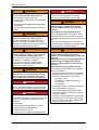
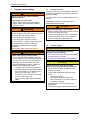
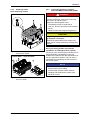
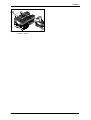
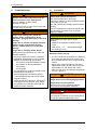
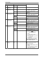
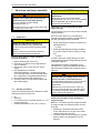
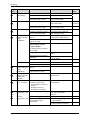
1
7
6
10
11
5
2
9
4
3
8
2bhxn402
Position
1
Description
Frequency inverter
2
Inlet connection with muffler and arrow indicating delivery direction
3
Discharge connection with muffler and arrow indicating delivery direction
4
Base
5
Arrow indicating direction of rotation
6
Blower cover
7
blower housing
8
Drive motor
9
Fan guard above the motor fan with rating plate, warning notices and arrow
indicating direction of rotation
10
Status display with 2 light-emitting diodes (red, green)
44
11
Communication interface for connecting the hand-held keypad
35
Fig. 1:
Design of side channel blowers in conjunction with frequency inverters
© Gardner Denver Deutschland GmbH
3 / 52
610.44520.40.000
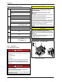
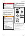
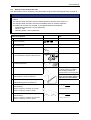
Quick start guide
Quick start guide
6 Adjust the speed.
A) Speed adjustment using a potentiometer
Side channel blowers are pre-configured for four
operating modes. It only takes a few steps and
they are ready for operation:
The speed is adjusted via the analog input.
The speed can be adjusted between
aminimum and a maximum
value.Description of potentiometer wiring
starts on page 30.
ACHTUNG
The drive motor is protected against
overheating by a thermal detector.
– If the drive motor gets too hot, the
frequency inverter will switch off the
pump-motor unit.
– Please contact the manufacturer if the
hydraulic process does not allow
immediate switch-off.
A minimum wiring is required for
commissioning! ( 22)
B) Operation with several adjustable fixed
speeds
The speed of the pump−motor unit can be
adjusted in steps of 1000/min via the digital
inputs E3 and E4.
Description of the wiring of E3 and E4
starts on page30.
C) Operation with one fixed speed
1 Read the safety instructions.
The safety instructions start on page 5.
2 Install the pump-motor unit and attach it.
Listing of the mounting steps starts on
page 16.
Connect hand−held keypad.
Set required fixed speed under C0140.
Disconnect hand−held keypad.
The pump−motor unit will be operated with
this speed when switched on.
Description of hand−held keypad
connection and parameter changing
starts on page35.
D) Speed adjustment using the keypad
3 Wire the pump-motor unit.
Please observe that a minimum wiring is
required!
Otherwise commissioning of the pumpmotor unit is not possible.
Important notes concerning the wiring
start on page 22.
4 Put the pump-motor unit into operation.
Description of the commissioning steps
starts on page 34.
Connect hand−held keypad.
Select C0140.
Set the required speed during the
process using the keys _..
The pump−motor unit will be operated with
the last set speed when switched on.
Description of hand−held keypad
connection and parameter changing
starts on page35.
5 Adapt important process parameters.
Adapt acceleration and deceleration time to
the hydraulic process via C0012 and
C0013.
Description of parameter changing
starts on page 35.
610.44520.40.000
4 / 52
© Gardner Denver Deutschland GmbH
Safety instructions
1
Safety instructions
1.1
CAUTION
Danger of injuries.
Indicates a potentially hazardous situation, that
may result in minor or moderate injury if the
corresponding measures are not taken.
Definitions
To point out dangers and important information,
the following signal words and symbols are used
in these Operating Instructions:
CAUTION
1.1.1
Safety alert symbols and signal words
The safety alert symbol is located in the safety
instructions in the highlighted heading field on the
left next to the signal word (DANGER,
WARNING, CAUTION).
Safety instructions with a safety alert symbol
indicate a danger of injuries.
Be sure to follow these safety instructions to
protect against injuries or death!
Safety instructions without a safety alert symbol
indicate a danger of damage. – Be sure to follow
these safety instructions to avoid material
damage!
1.1.2
Signal words
DANGER
WARNING
CAUTION
NOTICE
NOTE
The signal words are located in
the safety precautions in the
highlighted heading field.
They follow a certain hierarchy
and indicate (in conjunction with
the safety alert symbol, see
Chapter 1) the seriousness of
the danger and the type of
warning.
Danger of damage.
Indicates a potentially hazardous situation that
may result in property damage if the
corresponding measures are not taken.
NOTICE
Indicates a possible disadvantage, i.e.
undesirable conditions or consequences can
occur if the corresponding measures are not
taken.
NOTE
Indicates a possible advantage if the
corresponding measures are taken; tip.
1.1.3
Abbreviations used
Product designation
For side channel blower in conjunction with
frequency inverters the term pump−motor unit is
used in these Instructions.
Cross−reference
Cross−references to other parts of these
Instructions are marked with a book symbol:
( 9)
See the following explanations:
DANGER
Danger of injuries.
Indicates an imminently hazardous situation,
that will result in death or serious injury if the
corresponding measures are not taken.
WARNING
Danger of injuries.
Indicates a potentially hazardous situation, that
could result in death or serious injury if the
corresponding measures are not taken.
© Gardner Denver Deutschland GmbH
1.2
General safety and application notes
WARNING
Improper use of the pump−motor unit can
result in serious or even fatal injuries!
These Operating Instructions
must have been read completely and
understood before beginning any work with
or at the pump−motor unit,
must be strictly observed,
must be available at the operating location of
the pump−motor unit.
5 / 52
610.44520.40.000
Safety instructions
WARNING
DANGER!
Improper use of the pump−motor unit can
result in serious or even fatal injuries!
Electrical danger!
Do not open the frequency inverter until
absence of electricity has been ensured!
Only operate the pump−motor unit
for the purposes indicated under "Application
as directed"!
with the media indicated under "Application
as directed"!
with the values indicated under "Technical
data"!
WARNING
Danger due to vacuum and gauge pressure:
sudden escape of media (skin and eye
injuries), sudden drawing−in of hair and
clothing!
Improper use of the pump−motor unit can
result in serious or even fatal injuries!
All work on and with the pump−motor unit
(transport, installation, operation, shut−down,
maintenance, disposal) may only be carried out
by trained, reliable expert personnel!
Danger due to escaping media: burns!
Use mounting elements, connections, lines,
fittings and containers with sufficient freedom
from leaks and strength for the pressures which
occur.
Check the mounting elements, connections,
lines, fittings and containers for strength, leaks
and firm seating at regular intervals!
WARNING
WARNING
WARNING
When working on the pump−motor unit,
there is a danger of injury, e.g. in the form
of cuts/cutting off, crushing and burns!
During all work on and with the pump−motor
unit (transport, installation, operation,
shut−down, maintenance, disposal) wear
personal safety equipment (safety helmet,
safety gloves, safety shoes)!
WARNING
Hair and clothing can be pulled into the
pump−motor unit or caught and wound up
by moving parts! Do not wear long, loose
hair or wide, loose clothing! Use a hairnet!
DANGER!
Electrical danger!
Work on electrical installations may be carried
out by trained and authorized electricians only!
DANGER!
Electrical danger!
Before beginning work on the pump−motor unit
or system, the following measures must be
carried out :
Deenergize.
Secure against being switched on again.
Determine whether deenergized.
Ground and short−circuit.
Cover or block off adjacent energized parts.
610.44520.40.000
Danger from rotating parts (motor fan,
impeller, shaft): cutting/cutting off of
extremities, grasping/winding up of hair and
clothing!
Danger due to vacuum and gauge pressure:
sudden escape of media (skin and eye
injuries), sudden drawing−in of hair and
clothing!
Danger due to escaping media: burns!
Commissioning and operation only under the
following conditions:
The pump−motor unit must be completely
assembled. When doing so, pay particular
attention to the following components:
– the blower cover,
– the mufflers on inlet and discharge
connections,
– the fan guard.
The pipes and hoses must be connected to
inlet and discharge connections.
Inlet and discharge connections and the
connected pipes/hoses may not be closed,
clogged or soiled.
Check the mounting elements, connections
of the pipe/hose connections, lines, fittings
and containers for strength, leaks and firm
seating at regular intervals.
6 / 52
© Gardner Denver Deutschland GmbH
Safety instructions
WARNING
Danger from rotating parts (motor fan,
impeller, shaft): cutting/cutting off of
extremities, grasping/winding up of hair and
clothing!
Danger due to vacuum and gauge pressure:
sudden escape of media (skin and eye
injuries), sudden drawing−in of hair and
clothing!
Danger due to escaping media: burns!
Before beginning work on the pump−motor unit,
take the following measures :
Shut down pump−motor unit and secure
against being switched on again.
Attach a sign on the system controller and
on the control elements for the pump−motor
unit: "DANGER! Maintenance work on the
vacuum pump/compressor! Do not switch
on!"
Wait for pump−motor unit to come to a
complete stop.
– Observe run−on time!
Allow pump−motor unit to cool!
Shut−off lines.
– Release pressure.
Make sure that no vacuum or gauge
pressure is present in the lines/tanks to be
opened.
Make sure that no media can escape.
WARNING
Danger of burns from hot surface of the
pump−motor unit and from hot media!
High temperatures of up to approx. 160 °C
[320 °F] can occur on the surface of the
pump−motor unit:
Cover the pump−motor unit with a suitable
touch protection (e.g. perforated plate cover
or wire cover).
Do not touch during operation!
Allow to cool after shut−down!
1.3
Residual risks
WARNING
Danger zone:
Hot surface of up to approx.160 °C [320 °F].
Hazard:
Possible burns.
Protective measures:
Cover the pump−motor unit with a suitable
touch protection (e.g. perforated plate cover or
wire cover).
WARNING
Danger zone:
Fan guard
Hazard:
Long, loose hair can be drawn into motor fan
through the fan guard grate, even with
fan guard mounted!
Protective measures:
Wear hair net!
WARNING
Danger from rotating impeller:
cutting/cutting off of extremities!
The rotating impeller is accessible with the inlet
and discharge connections open!
Do not reach into the pump−motor unit through
open connections!
Do not insert objects into the pump−motor unit
through the openings!
WARNING
Danger from rotating impeller:
cutting/cutting off of extremities!
The rotating impeller is accessible with the inlet
and discharge connections open!
With free entry and exit of gases, i.e. with direct
intake out of or direct feeding into the
atmosphere without piping, the following
therefore applies:
Provide the inlet and discharge connections
of the pump−motor unit either with additional
mufflers or with additional piping of a
sufficient length to prevent access to the
impeller!
© Gardner Denver Deutschland GmbH
7 / 52
610.44520.40.000
Safety instructions
WARNING
CAUTION
Danger zone:
Missing or defective muffler on inlet or
discharge connection.
Hazard:
Possible serious hearing damage due to
emitted noise.
Protective measures:
Have missing or defective mufflers replaced.
Conduct a noise measurement in the system
after installing the pump−motor unit.
The following measures must be taken by the
operator:
from 85 dB(A):
– Hearing protection must be available.
from 90 dB(A):
– Mark noise area with a warning sign.
– Wear hearing protection.
WARNING
Danger zone:
Environment of pump−motor unit.
Hazard:
Possible serious hearing damage due to
emitted noise.
Danger zone:
Frequency inverter
Hazard:
Material damage at the frequency inverter
caused by switching on the device too
frequently with too short intervals.
Protective measures:
In the case of cyclic mains switching for a
longer time period, allow at least 3 minutes
between two switch−on actions.
CAUTION
Danger zone:
Side channel blower
Hazard:
Material damage at the side channel blower
caused by too high speeds.
Protective measures:
Do not set the output frequency at the
frequency inverter higher than the maximum
frequency specified in the documentation.
Use special overspeed monitors if
necessary.
Protective measures:
Conduct a noise measurement in the system
during operation after installing the
pump−motor unit.
The following measures must be taken by the
operator:
from 85 dB(A):
– Hearing protection must be available.
from 90 dB(A):
– Mark noise area with a warning sign.
– Wear hearing protection.
– With free entry and exit of gases, i.e. with
direct intake out of or direct feeding into
the atmosphere without piping, attach an
additional muffler.
610.44520.40.000
8 / 52
© Gardner Denver Deutschland GmbH
Safety instructions
1.4
Application as directed
Validity of the Operating Instructions
These Operating Instructions are valid for G-BH7e series side channel blower in conjunction with
frequency inverters equipped with the following frequency inverters:
2FC
4
xxx
- 1NE00 1x
35
2
Type
3
nash_elmo Industries GmbH
Industriestrasse 26
D-97616 Bad Neustadt
Supply voltage
4 = 400 V/500 V
Prod.-ID
Prod.-No.
Version
Ser.-No.
Input
Power
(e.g.152 = 15 ´ 102 W = 1,5 kW)
(e.g.. 752 = 75 ´ 102 W = 7,5 kW)
Output
1NE00 = integrated inverter
Type
Hardware version
1
Software version
ne2bhxn014
Fig. 2:
Typschild
These Operating Instructions
–
contain instructions bearing on transport and
handling, installation, commissioning,
operation, shut−down, storage, servicing and
disposal,
must be completely read and understood by
all operating and servicing personnel before
beginning to work,
must be strictly observed,
must be available at the site of operation in a
complete and perfectly legible condition.
are intended for industrial applications.
are designed for continuous operation:
–
–
Operating and servicing personnel
These persons must be trained and
authorized for the work to be carried out.
Work on electrical installations may be carried
out by trained and authorized electricians
only.
G-BH1e series side channel blower in
conjunction with frequency inverters
are pump−motor units for generating vacuum
or gauge pressure.
are used to extract, pump and compress the
following gases:
–
–
Air,
Non−flammable, non−aggressive,
non−toxic and non−explosive gases or
gas−air mixtures.
© Gardner Denver Deutschland GmbH
With differing gases/gas−air mixtures,
inquire with the manufacturer.
With increased switch−on frequency (at
equal intervals of approx. 5 times per hour)
or increased gas entry temperature and
ambient temperature, the limit
overtemperature of the winding and the
bearings can be exceeded.
Consultation with the manufacturer is
required for operating conditions of this
kind.
are equipped with a three−phase drive motor
with mounted frequency inverter.
are available in the following models:
–
–
–
single−impeller (single−stage)
two−impeller (two−stage)
three−impeller (three−stage)
Higher pressure differences can be achieved with
the two−impeller and three−impeller pump−motor
units.
are primarily intended for higher pressure
conditions;
During operation the limit values listed under
"Technical data" must always be complied with.
( 11)
9 / 52
610.44520.40.000
Safety instructions
1.5
Foreseeable Misuse
It is prohibited
to use the pump−motor units in applications
other than industrial applications unless the
necessary protection is provided on the
system, e.g. touch guards suitable for
children’s fingers,
to use the pump−motor units in rooms in
which explosive gases can occur,
to extract, deliver and compress explosive,
flammable, corrosive or toxic media,
to operate the pump−motor units with values
other than those specified in the chapter
"Technical data".
Any unauthorized modifications of the
pump−motor units are prohibited for safety
reasons.
The operator is only permitted to perform the
maintenance and service work described in these
Operating Instructions.
Any maintenance and service work which goes
beyond this many only be performed by
companies authorized by the manufacturer
(inquire with the manufacturer).
610.44520.40.000
10 / 52
© Gardner Denver Deutschland GmbH
Technical data
2
2.1.2
Technical data
2.1
2.1.1
Measurement conditions
Mechanical data
Weights
Type
Weight
approx. [kg]
approx. [lbs]
Single−impeller design
2BH7210−0.N1
20
44
2BH7210−0.N5
32
71
2BH7310−0.N2
20
44
2BH7310−0.N6
35
77
2BH7410−0.N1
27
60
2BH7410−0.N5
42
93
2BH7510−0.N2
39
86
2BH7510−0.N6
48
106
2BH7610−0.N3
45
99
2BH7220−0.N5
38
84
2BH7320−0.N5
40
88
2BH7320−0.N8
46
101
2BH7420−0.N2
43
95
2BH7420−0.N5
49
108
2BH7520−0.N7
61
134
2BH7620−0.N3
58
128
2BH7620−0.N4
68
150
96
212
Two−impeller design
Three-impeller design
2BH7630−0.N6
Noise level
Measuring-surface sound-pressure level as per
EN ISO 3744, measured at a distance of 1 m
[3.28 ft] at an operating point of approximately
2/3 of the permissible total pressure difference
with the lines connected without a vacuum or
pressure relief valve, tolerance 3 dB (A).
Type
1−m measuring−surface
sound−pressure level L for
operation with output
frequency [dB(A)]
50 Hz
60 Hz
86 Hz
Single−impeller design
2BH7210−0.N1
70
70
74
2BH7210−0.N5
70
70
74
2BH7310−0.N2
70
70
76
2BH7310−0.N6
70
70
76
2BH7410−0.N1
70
70
76
2BH7410−0.N5
70
70
76
2BH7510−0.N2
70
70
78
2BH7510−0.N6
70
70
78
2BH7610−0.N3
70
71
77
2BH7220−0.N5
70
70
74
2BH7320−0.N5
70
70
76
2BH7320−0.N8
70
70
76
2BH7420−0.N2
70
70
76
2BH7420−0.N5
70
70
76
2BH7520−0.N7
70
70
78
2BH7620−0.N3
70
71
80
2BH7620−0.N4
70
71
80
77
80
80
Two−impeller design
Three-impeller design
2BH7630−0.N6
© Gardner Denver Deutschland GmbH
11 / 52
610.44520.40.000
Technical data
2.1.3
Tightening torques for screw connections
Temperature increase
The information listed in the following tables
corresponds to the heating of the side channel
housing and the air exiting compared to the
ambient temperature during operation with a
permissible total pressure difference and an air
pressure of 1013 mbar [14.7 psi]. At lower air
pressures these values increase.
Type
The following values apply if no other data are
given.
With non−electrical connections, property classes
of 8.8 and 8 or higher as per DIN ISO 898 (DIN
EN 20898 / DIN ISO 898) are assumed.
Tightening torques for
non−electrical connections
Temperature increase for
operation with output
frequency (approx.)
50 Hz
∆T
[K]
∆υ
[F]
60 Hz
∆T
[K]
∆υ
[F]
86 Hz
∆T
[K]
∆υ
[F]
Single−impeller design
Thread
[Nm]
[lb-in]
M4
2,7 … 3,3
23,9 … 29,2
M5
3,6 … 4,4
31,9 … 38,9
M6
7,2 … 8,8
63,7 … 77,9
2BH7210−0.N1
52 126
61
142
M8
21,6 … 26,4
191 … 234
2BH7210−0.N5
52 126
77
171
M10
37,8 … 46,2
335 … 409
187
M12
63,0 … 77,0
558 … 681
2BH7310−0.N2
81 178
86
2BH7310−0.N6
88 190 112 234
2BH7410−0.N1
90 194 101 214
2BH7410−0.N5
114 237 120 248
2BH7510−0.N2
120 248 112 243
2BH7510−0.N6
120 248 120 248
2BH7610−0.N3
118 244 124 255
Tightening torques for cable
and conduit glands Metal
≤
≤
120 248
Two−impeller design
2BH7220−0.N5
55
131
2BH7320−0.N5
81
178 124 255
2BH7320−0.N8
120 248 120 248
2BH7420−0.N2
89
192
86
80
186
[Nm]
[lb-in]
M12x1,5
4,0 … 6,0
35,4 … 53,1
M16x1,5
5,0 … 7,5
44,3 … 66,4
M20x1,5
6,0 … 9,0
53,1 … 79,7
8,0 … 12,0
70,8 … 106
M32x1,5
M40x1,5
Tightening torques for cable
and conduit glands Plastic
176
2BH7420−0.N5
≤
≤
120
248
121 250 117 243
2BH7520−0.N7
125 257 110 230
2BH7620−0.N3
124 255 126 259
2BH7620−0.N4
124 255 126 259
Three-impeller design
2BH7630−0.N6
Thread
120 248 120 248
≤
≤
120 248
Thread
[Nm]
[lb-in]
M12x1,5
2,0 … 3,5
17,7 … 31,0
M16x1,5
3,0 … 4,0
26,6 … 35,4
M20x1,5
4,0 … 5,0
35,4 … 44,3
5,0 … 7,0
44,3 … 62,0
M32x1,5
M40x1,5
2.2
Electrical data
See rating plate.
610.44520.40.000
12 / 52
© Gardner Denver Deutschland GmbH
Technical data
2.3
General data/operating conditions
Conformity
CE
Low−Voltage Directive
Vibration resistance
Acceleration resistant up to 2g (Germanischer Lloyd, general conditions)
Vibration velocity
max. veff 4 mm/s
[0,013 ft/s]
Depending on the application case and the
system type it may be necessary to use vibration
dampers.
Site altitude
min. 0 m üNN
[0 ft amsl]
max. 1000 m üNN [3280 ft amsl]
For installations above 1000 m amslA [3280 ft
amsl] consultation of the manufacturer is
required.
Climatic conditions
Class 3K3 to EN 50178 (without condensation, relative humidity 30 ... 95 %)
Ambient temperatures
Transport
Storage
Operation
min.
-25°C
[-13°F]
max.
+70°C
[+158°F]
min.
-25°C
[-13°F]
max.
+60°C
[+140°F]
min.
-20°C
[-4°F]
max.
+40°C
[+104°F]
rated value
+25°C
[+77°F]
max.
+40°C
[+104°F]
rated value
+15°C
[+59°F]
Between +25 °C [+77 °F] and +40 °C [+104 °F]
reduce the total pressure difference indicated on
the rating plate by 0.7 %/°C [0.4 %/°F].
Operation at higher temperatures may damage
the winding and shorten the grease change
interval.
Temperature of pumped gases
Pump−motor units for higher media
temperatures Pump on request.
Pressures
Inlet pressure
min. See rating plate
Discharge pressure
during compressor
operation
max. See rating plate
Permissible total
pressure difference
max. See rating plate
zulässiger Druck im
Aggregat
max.
© Gardner Denver Deutschland GmbH
2 bar abs.
The total pressure difference specified on the
rating plate only applies under the following
conditions:
[29 psia]
13 / 52
Ambient temperature: 25 °C [77 °F]
Temperature of the pumped gas at the inlet
connection: 15 °C [59 °F]
Pressure:
– for vacuum−pump operation: 1013 mbar
[14.7 psia] at the discharge connection
– for compressor operation:
1013 mbar [14.7 psia] at the inlet
connection
At this pressure the operation of the
pump−motor unit may be considerably impaired.
Provide a corresponding protective device (e.g.
pressure relief valve) if necessary.
610.44520.40.000
Transport and handling
3
Transport and handling
WARNING
Tipping or falling can lead to crushing,
broken bones etc.!
Sharp edges can cause cuts!
Wear personal safety equipment (safety
gloves, safety shoes and safety helmet)
during transport!
WARNING
Danger from lifting heavy loads!
Manual handling of the pump−motor unit is only
permitted within the following limits:
max. 30 kg [max. 66 lbs] for men
max. 10 kg [max. 22 lbs] for women
max. 5 kg [max. 11 lbs] for pregnant women
For weights above the given values use
suitable lifting appliances and handling
equipment!
Weight of the pump−motor units: ( 11)
WARNING
Danger from tipping or falling loads!
Prior to transport and handling make sure
that all components are securely assembled
and secure or remove all components the
fasteners of which have been loosened!
When transporting with lifting equipment,
observe the following basic rules:
– The lifting capacity of lifting equipment
and lifting gear must be at least equal to
the unit’s weight. For the weight of the
pump−motor units see:: ( 11)
– The pump−motor unit must be secured
so that it cannot tip or fall.
– Do not stand or walk under suspended
loads!
610.44520.40.000
3.1
Transport devices
All pump−motor units with a weight of more than
30 kg are equipped with an eye bolt at the side
channel housing.
The crane hook can be hooked directly into the
eye bolt.
Alternatively the pump−motor units can be
transported with lifting belts.
WARNING
Danger from tipping or falling loads!
Place the lifting belts under the side channel
housing and under the motor.
Attach the lifting belts in such a way that the
suspending pump−motor unit is balanced
and cannot slip out of the lifting belts.
3.2
Transport types
CAUTION
Pump−motor unit damage caused by
improper manual handling!
Do not carry the pump−motor unit by holding
it at the frequency inverter!
Avoid heavy impact loads during transport.
CAUTION
Pump−motor unit damage caused by
improper transport with lifting appliances!
Do not attach the lifting appliances to the
frequency inverter!
The eye bolt at the side channel housing
must
– be screwed tightly.
– be exactly in axial direction of the
pump−motor unit. Lay shims under the
eye bolt if necessary.
Loads laterally to the ring level are not
permissible.
Avoid heavy impact loads during transport.
14 / 52
© Gardner Denver Deutschland GmbH
Transport and handling
Type
Type of transport
manually
with lifting
appl.
Single−impeller design
2BH7210−0.N1
X
2BH7210−0.N5
2BH7310−0.N2
X
X
2BH7310−0.N6
2BH7410−0.N1
X
X
2BH7410−0.N5
X
2BH7510−0.N2
X
2BH7510−0.N6
X
2BH7610−0.N3
X
Two−impeller design
2BH7220−0.N5
X
2BH7320−0.N5
X
2BH7320−0.N8
X
2BH7420−0.N2
X
2BH7420−0.N5
X
2BH7520−0.N7
X
2BH7620−0.N3
X
2BH7620−0.N4
X
Three−impeller design
2BH7630−0.N6
© Gardner Denver Deutschland GmbH
X
15 / 52
610.44520.40.000
Installation
4
Installation
WARNING
Improper use of the pump−motor unit can
result in serious or even fatal injuries!
Have you read the chapter "Safety
instructions"? ( 5)
Otherwise you may not carry out any work with
or on the pump−motor unit!
DANGER!
Danger from missing view into area of
pump−motor unit!
When operating the control elements without a
view into the area of the pump−motor unit,
there is a danger that the pump−motor unit will
be switched on while other persons are still
performing work on it. Severest injuries are
possible!
Provide control elements at a location with a
view of the pump−motor unit.
DANGER!
Electrical danger!
The pump−motor unit must be installed so that
the electrical equipment cannot be damaged by
external influences!
In particular, the incoming cables must be
routed securely, e.g. in cable ducts, in the floor
etc.
WARNING
Danger of crushing due to pump−motor unit
tipping over!
Wear personal safety equipment (safety gloves
and safety shoes).
Handle the pump−motor unit with the
appropriate care.
Install the pump−motor unit on a solid
foundation or on a solid mounting surface!
Check screw glands/unions for mounting the
pump−motor unit on the mounting surface
regularly for strength.
WARNING
Danger of fire from flammable substances!
The pump−motor unit must never come into
contact with flammable substances.
For exact information on the temperature
increase see: ( 12).
WARNING
Danger of burns from hot surface of the
pump−motor unit and from hot media!
High temperatures of up to approx. 160 °C
[320 °F] can occur on the surface of the
pump−motor unit.
The pump−motor unit must be installed so that
accidental touch of its surface is not possible.
Cover the pump−motor unit with a suitable
touch protection (e.g. perforated plate cover or
wire cover).
WARNING
Danger of balance damage caused by
vibration!
Vibrating environments can cause balance
damage!
Install the pump−motor unit on a solid
foundation or on a solid mounting surface.
Check screw glands/unions for mounting the
pump−motor unit on the mounting surface
regularly for strength and firm seating.
610.44520.40.000
WARNING
Danger of injuries from flying parts!
Select installation so that parts that are thrown
out through the grate if the motor fan breaks
cannot hit persons!
CAUTION
Danger of tripping and falling!
Make sure the pump−motor unit does not
present a danger of tripping.
Lay cables and pipes so that they cannot be
reached during operation (recessed in floor, in
ducts on the wall etc.).
16 / 52
© Gardner Denver Deutschland GmbH
Installation
CAUTION
Danger of overheating due to hot surface of
pump−motor unit!
High temperatures can occur on the surface of
the pump−motor unit.
Temperature−sensitive parts, such as cables or
electronic components, may not come into
contact with the surface of the pump−motor
unit.
CAUTION
Danger of pump−motor unit damage caused
by penetration of foreign bodies!
On delivery all connection openings are closed
in order to prevent the penetration of foreign
bodies. Remove the seals right before the
respective mounting step.
Installation sequence
The pump−motor unit is ready to connect on
delivery.
CAUTION
The pump−motor unit may be damaged if it
is installed and commissioned after longer
storage periods without special preparation!
If the pump−motor unit was stored for a longer
period prior to installation, it has to be prepared
for installation: ( 42)
Carry out the following steps to install the
pump−motor unit:
1 Set up the pump−motor unit and attach it.
2 Mount the muffler (supplied loose) if
necessary.
3 Mount the threaded flange or hose flange to
the muffler if necessary.
4 Connect inlet and discharge connections to
the system.
5 Establish electrical connection.
4.1
Installation
CAUTION
Pump−motor unit damage caused by
incorrect mounting or use under
impermissible ambient conditions!
Install and connect the pump−motor unit only
according to the instructions given in this
chapter.
If the pump−motor unit is to be used under
differing operating conditions, the manufacturer
must be consulted.
NOTE
Dimensioned drawings with detailed
dimensions, including fastening dimensions,
are provided by the manufacturer.
4.1.1
Ambient conditions
The pump−motor unit is suitable for installation
in a dusty or damp environment,
in buildings,
in the open.
–
–
For proper installation in the open, protect
the pump−motor unit from exposure to
intensive sunlight, e.g. by attaching a
protective roof.
Further special protective devices against
the effects of weathering are not required.
The motors of the units are to enclosure IP55.
The insulation is tropic−proof.
Installation conditions
Attach the pump−motor unit only to even
surfaces.
Do not exceed the maximum permissible
vibration velocity veff = 4mm/s [0.013 ft/s].
Installation altitude max. 1000 m amsl [3280 ft
amsl].
–
© Gardner Denver Deutschland GmbH
Important notes
17 / 52
When installing at an altitude of more than
1000 m [3280 ft] above sea level, first
inquire with the manufacturer.
610.44520.40.000
Installation
4.1.2
Noise radiation
Free spaces
In order to reduce the noise radiation,
CAUTION
do not mount pump−motor unit on
noise−conducting or noise−radiating parts
(e.g. thin walls or sheet−metal plates).
provide pump−motor unit with
sound−insulating intermediate layers (e.g.
rubber buffers under the base of the
pump−motor unit) if necessary.
install the pump−motor unit on a stable
foundation or on a rigid mounting surface.
This will ensure quiet and low−vibration
running of the pump−motor unit.
Components for reducing noise on the
pump−motor unit:
Material damage caused by overheating of
the pump−motor unit!
It is absolutely necessary to observe the
required free spaces in order to cool the
pump−motor unit sufficiently.
Ventilation screens and ventilation openings
must remain clear.
The discharge air of other pump−motor units
may not be directly sucked in again!
> 100 mm
[ > 4 in ]
Muffler (included in the scope of supply)
–
–
> 100 mm
> 100 mm
[ > 4 in ]
[ > 4 in ]
On delivery the pump−motor units are
equipped with attached mufflers as
standard.
The mufflers considerably reduce the noise
radiation.
Additional muffler (available as accessories):
–
–
The additional mufflers enable a further
noise reduction.
They may only be used in systems without
piping, i.e. with direct intake out of the
atmosphere or direct feeding into the
atmosphere.
Noise protection hoods (available as
accessories):
–
–
Noise protection hoods are suitable for
installation in rooms and in the open.
They reduce the overall sound pressure
level and tonal components that are
perceived as particularly annoying.
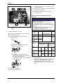
a
b
Ne2bhxn001
Type
a
[mm]
b
[in]
2BH72..
Installation variants
2BH73..
Units with motors without condensation water
openings can be installed in different ways:
2BH74..
horizontally,
vertically on the cover of the side channel
housing ("cover installation"),
vertically on a wall.
2BH76..
> 30
> 1,18
2BH75..
Fig. 3:
[mm]
[in]
> 34
> 1,34
> 52
> 2,05
> 53
> 2,09
Free spaces
CAUTION
Danger of rusting due to collection of
condensed water in drive motor area!
Install and attach units with motors equipped
with condensation water openings only
horizontally, base at the bottom.
610.44520.40.000
18 / 52
© Gardner Denver Deutschland GmbH
Installation
4.1.3
Mounting
NOTE
Dimensioned drawings with detailed
dimensions, including fastening dimensions,
are provided by the manufacturer.
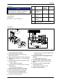
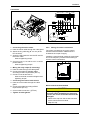
Horizontal installation
ne2bhxn002c
Fig. 5:
Schematic diagram: installation on the cover
of the side channel housing
Mounting sequence:
ne2bhxn002d
Fig. 4:
Schematic diagram: horizontal installation
Mounting sequence:
1 Select suitable mounting elements.
2 Attach the pump−motor unit to the surface:
– Screw the base of the pump−motor unit to
the surface via the mounting holes.
– When doing so, be sure to provide all
mounting holes with screws!
1 Attach the rubber feet to the pump−motor unit:
– Screw the stud bolts of the rubber feet into
the bore holes in the cover of the gas ring
blower housing.
– Tighten the rubber feet.
2 Mount the pump−motor unit together with the
rubber feet on the installation surface:
– Select suitable mounting elements for the
threaded hole.
– Screw the rubber feet to the installation
surface via the threaded holes.
Vertical mounting on a wall
Vertical installation on the cover of the gas
ring blower (”cover installation”)
NOTE
You need three rubber feet for the "cover
installation" of the pump−motor unit.
The rubber feet are available as accessories.
They come with a stud bolt on one side and a
threaded hole on the other side.
ne2bhxn002a
WARNING
Danger of crushing caused by pump−motor
unit tipping over!
Avoid free−standing installation of the
pump−motor unit!
Always screw the rubber feet to the foundation
or to the installation surface!
Check screw connections regularly for
tightness.
ne2bhxn002b
Fig. 6: Schematic diagram: vertical mounting on a
wall
Mounting sequence:
© Gardner Denver Deutschland GmbH
19 / 52
610.44520.40.000
Installation
1 Select suitable mounting elements.
2 Position the pump−motor unit as close to the
wall as possible on a stable supporting plate
with sufficient load−bearing capacity.
– The pump−motor unit must be positioned
with the base towards the wall.
2BH732 ... 2BH762 (two−impeller pump−motor
units with two−stage design)
3 Attach the pump−motor unit to the wall:
– Screw the base of the pump−motor unit to
the wall via the mounting holes.
– When doing so, be sure to provide all
mounting holes with screws!
ne2bhxn003b
Fig. 8:
4 Remove the supporting plate.
4.1.4
Mounting of the muffler 2BH732 ... 2BH762
2BH763 (three−impeller pump−motor unit with
three−stage design)
Final works
After installing the pump−motor unit, the eye bolt
must be removed or screwed tightly.
ne2bhxn003c
4.2
Mounting of the muffler
Fig. 9: Mounting of the muffler 2BH763
The pump−motor units are supplied with mufflers
for inlet and discharge connections as standard.
The mufflers are marked by arrows in the
following drawings.
2BH721 ...2BH761 (single−impeller pump−motor
units)
WARNING
Danger from rotating impeller:
cutting/cutting off of extremities!
The rotating impeller is accessible with the inlet
and discharge connections open!
With free entry and exit of gases, i.e. with direct
intake out of the atmosphere or direct feeding
into the atmosphere without piping, the
following therefore applies:
Provide the inlet and discharge connections of
the pump−motor unit either with additional
mufflers or with additional piping of a sufficient
length to prevent access to the impeller!
ne2bhxn003a
Fig. 7: Mounting of the muffler 2BH721 ...2BH761.
With the following pump−motor units, the
inlet−side muffler is included loose for
packaging−related reasons. It must be mounted
by the operator.
4.3
4.3.1
Connecting the pump-motor unit to the
system
Important notes
Delivery direction of the gases
The pumped gases are sucked in via the inlet
connection and discharged via the discharge
connection.
The delivery direction of the gases is marked by
arrows on the connections:
The inlet connection with the corresponding
muffler is marked by an arrow pointing into the
pump−motor unit.
The discharge connection with the
corresponding muffler is marked by an arrow
pointing out of the pump−motor unit.
610.44520.40.000
20 / 52
© Gardner Denver Deutschland GmbH
Installation
4.3.2
Rotation direction of the shaft
The rotation direction of the shaft is marked by an
arrow on the cover of the side channel housing
and by an arrow on the fan guard of the motor.
WARNING
Danger from interchanging inlet and
pressure line!
Interchanged inlet and pressure lines can lead
to damage to the pump−motor unit and the
system, and as a result of this to serious
injuries!
Make sure that the inlet and the pressure line
cannot be confused when connecting.
Pay attention to the clear marking with the
arrows indicating the delivery direction on the
inlet and discharge connections.
WARNING
Danger due to vacuum and gauge pressure!
Danger due to escaping media!
During operation, connected pipes and vessels
are vacuumized or pressurized!
Use only mounting elements, connections,
lines, fittings and containers with sufficient
freedom from leaks and strength for the
pressures which occur.
Make sure that the mounting elements and
connections are mounted firmly enough and
leak−free!
CAUTION
If the pumped gases are passed on the
discharge side in a closed pipe system, then it
must be ensured that the pipe system is
adapted to the maximum discharge pressure.
Connect a pressure relief valve upstream if
necessary.
NOTE
Attach pipes/hoses free of mechanical
tensions.
Support the weight of the pipes/hoses.
© Gardner Denver Deutschland GmbH
Connecting the inlet line
WARNING
Danger from solid bodies and impurities in
the pump−motor unit!
If solid bodies penetrate into the pump−motor
unit, blades of the impellers can break and
broken pieces can be thrown out.
Install a filter in the inlet line. Replace filter
regularly!
The pumped gases are taken in via the inlet line.
Connect the inlet line to the inlet connection.
–
The inlet connection with the
corresponding muffler is marked by an
arrow pointing into the pump−motor unit.
A If you use an inlet pipe, you can screw it
directly into the muffler.
B If you use an inlet hose, you need a hose
flange available as accessories:
– Screw the hose flange to the muffler.
– Push the hose onto the hose flange and
secure it with a hose clamp.
– Observe tightening torques ( 12)
4.3.3
Connecting the pressure line
The pumped gases are discharged via the
pressure line.
Connect the pressure line to the discharge
connection.
–
The discharge connection with the
corresponding muffler is marked by an
arrow pointing out of the pump−motor unit.
A If you use a pressure pipe, you can screw it
directly into the muffler.
B If you use a pressure hose, you need a hose
flange available as accessories:
– Screw the hose flange to the muffler
– Push the hose onto the hose flange and
secure it with a hose clamp.
– Observe tightening torques ( 12)
21 / 52
610.44520.40.000
Installation
4.4
Electrical installation
DANGER!
Electrical danger!
Malpractice can result in severe injuries and
material damage!
DANGER!
Electrical danger!
The electrical connection may be carried out by
trained and authorized electricians only!
DANGER!
Electrical danger!
Before beginning work on the pump−motor unit
or system, the following measures must be
carried out:
Deenergize.
Secure against being switched on again.
Determine whether deenergized.
Ground and short−circuit.
Cover or block off adjacent energized parts.
DANGER!
Electrical danger!
The terminal box of the frequency inverter must
be free from
foreign bodies,
dirt,
humidity.
Frequency inverter and cable entries must be
tightly closed so as to make them dustproof
and waterproof. Check for tightness at regular
intervals.
DANGER!
4.4.1
Important notes
Regulations
The electrical connection must be carried out as
follows:
according to the corresponding VDE
regulations and national regulations.
according to the applicable national, regional
and system−dependent regulations and
requirements.
according to the regulations of the utility
company applying to the place of installation.
Electrical power supply
Observe the rating plate of the frequency
inverter. It is imperative that the operating
conditions correspond to the data given on the
rating plate.
Electrical connection ( 23), ( 26)
The electrical connection must be
permanently safe.
The electrical connection to the PE conductor
must be permanently safe.
There may be no protruding wire ends.
Control cable connection ( 29)
Use shielded incoming cables.
Do not route control cables together with
power cables in order to avoid interference
injections.
For optimum shielding use the shield
connections to ensure large−surface contact
when connecting the shield in the terminal
box.
Control cables
Electrical danger!
Danger of electrical shock when a defective
pump−motor unit is touched!
Have electrical equipment checked regularly by
a qualified electrician.
610.44520.40.000
22 / 52
© Gardner Denver Deutschland GmbH
Installation
4.4.2
4.4.3
Preparing works
Open frequency inverter
Connecting frequency inverters
2FC4152-1NE00 and 2FC4222-1NE00
DANGER!
2FC4152-1NE00 ... 2FC4222-1NE00
Electrical danger!
Improper connection of the pump−motor unit
can result in an electric shock.
Observe the following basic rules:
The leakage current to earth (PE) is
>3.5 mA. The PE connection must meet EN
50178.
Observe national and regional regulations.
CAUTION
Danger of pump−motor unit damage caused
by improper connection!
Observe the permissible mains voltage. Any
higher mains voltage will destroy the frequency
inverter.
ne2bhxn222
Fig. 10: Open frequency inverters 2FC4152−1NE00
and 2FC4222−1NE00
The pump−motor units meet the EU Directive on
"Electromagnetic Compatibility" if they are
installed in accordance with the specifications of
the CE−typical drive system. The end−user is
responsible for maintaining the EU Directive in
the overall system.
2FC4302-1NE00 ... 2FC4752-1NE00
1
Wiring according to EMC requirements
(installation of a CE-typical drive system)
2
NOTE
Requirements for trouble−free operation:
Always shield control cables.
Provide large−surface contact between
shielding and shield sheet. Ensure good
electrical contact.
ne2bhxn422
Fig. 11: Open frequency inverters 2FC4302−1NE00 ...
2FC4752−1NE00
© Gardner Denver Deutschland GmbH
23 / 52
610.44520.40.000
Installation
X1 Terminal strip for mains connection and relay
output connection
2FC4152-1NE00 ... 2FC4222-1NE00
D B
C
A
X2 Terminal strip for motor connection and motor
temperature monitoring
PES HF shield termination by large−surface
connection to PE
X1
Mains contactor, fuses and cable crosssections
NOTE
X2
F
E
1ne2bhxn101
Fig. 12: Terminal box 2FC4152-1NE00 ... 2FC42221NE00
Mains cable L1, L2, L3, PE
PE connection mains cable and motor cable
Shielded control cable
Shield connection for the control cable::
1 Prepare cable
Observe the following when using earth
leakage circuit breakers:
Install earth leakage circuit breakers only
between the supply mains and the frequency
inverter.
The earth leakage circuit breaker may trip
incorrectly if several drives are
simultaneously connected to the mains.
Frequency
inverter
Type
[kW]
1,5
2FC42221NE00
2,2
Pass the cable through the eye of the
shield sheet and bend the eye.
contactor K1
2FC41521NE00
Frequency
inverter
2
Required mains
Type
[kW]
FI 2)
4
≥30 m
A
Fuses and cable cross sections
Installation according Installation
to EN 60204−1
according to
UL 1)
L1, L2,
L3, PE
[mm2]
3
Screw together eye and shield sheet:
– The shielding must have large−surface
contact to the shield sheet.
– The shielding must be connected tightly
to the shield sheet.
0.7 Nm
6 lb-in
L1, L2,
L3, PE
[AWG]
2FC41521NE00
M6 A B6 A
1
5A
18
2FC42221NE00
M10
B10 A
A
1,5
10 A
16
1)
2)
Fuse
Circuit−breaker
Use only UL−approved cables, fuses and fuse
holders. UL−fuse: voltage 500 ... 600 V,
tripping characteristic "H", "K5" or "CC"
Pulse current sensitive or all current sensitive
e.l.c.b.
PES
Potential free terminal
Control terminal module
610.44520.40.000
24 / 52
© Gardner Denver Deutschland GmbH
Installation
Relay data
Function
NOTE
X1/K11 Relay output
normally−close
d contact
The service life of the relay depends on the
type of load (ohmic, inductive or capacitive)
and the value of the switching capacity.
Relay
position
switched
Displayed
message
opened
TRIP
closed
TRIP
X1/K12 Relay
mid−position
contact
Technical data
AC 250 V/3 A
X1/K14 Relay output
normally−open
contact
DC 24 V/2 A ... DC 240 V/0.22 A
PES
HF shield termination by large−surface
connection to PE
Connection
3/PE AC, 320 V ... 550 V, 45 ... 65 Hz
X1
0.5...0.6 Nm
4.4...5.3 lb-in
PES
PES
X1
L3
L2
L1 BR2 BR1 BR0 K14 K12 K11
5.3 mm
1.2...1.5 Nm
10.7...13.3 lb-in
ne2bhxn231
Fig. 13: Frequency inverter 2FC4152-1NE00 ... 2FC4222-1NE00 1
1 Connecting the mains cable:
A Release two screws at terminal X1 and
remove the terminal.
B Pass the mains cable through the cable gland.
C Attach the ring cable lug ( 5.3 mm) to the PE
conductor.
D Screw the PE conductor onto the PE stud for
the mains cable:
– observe tightening torque!
E Connect cores L1, L2 and L3 to X1 in correct
phase relation:
– observe tightening torque!
–
connecting
observe terminal connection diagram and
tightening torque!
3 Re−insert terminal X1 and tighten with 2
screws:
– observe tightening torque!
4 Connecting the control cable shield:
A Pass the control cable through the cable
gland.
B Connect the shield according to EMC
requirements ( 24).
C Control cable connection: ( 29)
5 Tighten all cable glands.
2 Wiring the relay output (if necessary):
A Pass the cable through the cable gland.
B Connect the shield of shielded cables
according to EMC requirements ( 24).
C Connect cores to terminal X1:
© Gardner Denver Deutschland GmbH
25 / 52
610.44520.40.000
Installation
NOTE
Do not remove the jumper between terminals
BR1 and BR0!
Otherwise trouble−free functioning of the
pump−motor unit cannot be guaranteed.
4.4.4
Connecting frequency inverters
2FC4302-1NE00 ... 2FC4752-1NE00
DANGER!
Electrical danger!
Improper connection of the pump−motor unit
can result in an electric shock.
Observe the following basic rules:
The leakage current to earth (PE) is > 3.5
mA. The PE connection must meet EN
50178.
Observe national and regional regulations.
CAUTION
Danger of pump−motor unit damage caused
by improper connection!
Observe the permissible mains voltage. Any
higher mains voltage will destroy the frequency
inverter.
Wiring according to EMC requirements
(installation of a CE-typical drive system)
The pump−motor units meet the EU Directive on
"Electromagnetic Compatibility" if they are
installed in accordance with the specifications of
the CE−typical drive system. The end−user is
responsible for maintaining the EU Directive in
the overall system.
NOTE
Requirements for trouble−free operation:
Always shield control cables.
Provide large−surface contact between
shielding and shield sheet. Ensure good
electrical contact.
610.44520.40.000
26 / 52
© Gardner Denver Deutschland GmbH
Installation
Realisation
A
B
X1
G
E
H
X2
D
C
F
2ne2bhxn398
Fig. 14: Electrical connections 2FC4302-1NE00 … 2FC4752-1NE00
Mains cable L1, L2, L3, PE
3 Insert cable and tighten cable tie:
PE connection mains cable
–
Shielded control cable
–
Shield connection for the control cable: g:
1 Prepare cable..
The shielding must have large−surface
contact to the shield sheet.
The shielding must be connected
tightly to the shield sheet.
ne2bhxn047
ne2bhxn045
2 Insert cable tie..
Potential−free terminals
PE connection motor
Support for control terminal module
Control terminal module
X1 Terminal strip for mains connection and relay
output connection
ne2bhxn046
X2 Terminal strip for motor connection
PES HF shield termination by large−surface
connection to PE
© Gardner Denver Deutschland GmbH
27 / 52
610.44520.40.000
Installation
Relay data
Mains contactor, fuses and cable crosssections
NOTE
NOTE
The service life of the relay depends on the
type of load (ohmic, inductive or capacitive)
and the value of the switching capacity.
Observe the following when using
earth−leakage circuit breakers:
Install earth−leakage circuit breakers only
between the supply mains and the frequency
inverter.
The earth−leakage circuit breaker may trip
incorrectly if several drives are
simultaneously connected to the mains.
Technical data
AC 250 V/3 A
DC 24 V/2 A … DC 240 V/0.22 A
Function
Frequency
inverter
Required mains
contactor K1
Type
[kW]
[kW]
2FC43021NE00
3
3
2FC44021NE00
4
4
2FC45521NE00
5,5
5,5
2FC47521NE00
7,5
7,5
Frequency
inverter
≥300 mA
opened
TRIP
closed
TRIP
HF shield termination by large−surface
connection to PE
Installation according Installation
to EN 60204-1
according to
UL 1)
L1, L2,
L3, PE
L1, L2,
L3, PE
[AWG]
2FC43021NE00
M16
A
B16 A
2,5
15 A
14
2FC44021NE00
M20
A
B20 A
4
20 A
12
2FC45521NE00
M25
A
B25 A
4
25 A
10
2FC47521NE00
M32
A
B32 A
6
35 A
8
2)
X1/K14 Relay output
normally−open
contact
PES
[mm2]
1)
Displayed
message
X1/K12 Relay
mid−position
contact
Fuses and cable cross sections
Type
X1/K11 Relay output
normally−close
d contact
FI 2)
Relay
position
switched
Fuse
Circuit−breaker
Use only UL−approved cables, fuses and fuse
holders. UL−fuse: voltage 500 ... 600 V,
tripping characteristic "H", "K5" or "CC"
All−current sensitive e.l.c.b.
610.44520.40.000
28 / 52
© Gardner Denver Deutschland GmbH
Installation
Connection
3/PE AC, 320 V ... 550V, 45 ... 65 Hz
1.1 Nm
9.7 lb-in
PES
PES
4.3 mm
X1 K14 K12 K11 L3
1.2...1.5 Nm
10.7...13.3 lb-in
L2
L1
6 mm
ne2bhxn431
Fig. 15: Connectiing frequency inverter 2FC4302-1NE00 ... 2FC4752-1NE00
1 Connecting the mains cable:
A Pass the mains cable through the cable gland.
B Attach the ring cable lug (Ø 4.3 mm) to the
PE conductor.
C Screw the PE conductor onto the PE stud for
the mains cable:
– observe tightening torque
4.4.5
Wiring of control connections
The control connections are on the control
terminal module 2FX4501−0NE00 which is
included in the scope of supply.
Install the control terminal module in the terminal
box of the frequency inverter before starting to
wire the control connections.
D Connect cores L1, L2 and L3 to X1 in correct
phase relation:
– observe tightening torque!
2 Wiring the relay output (if necessary):
A Pass the cable through the cable gland.
B Connect the shield of shielded cables
according to EMC requirements ( 27).
C Connect cores to terminal X1:
– observe terminal connection diagram and
tightening torque!
3 Connecting the control cable shield:
A Pass the control cable through the cable
gland.
B Connect the shield according to EMC
requirements ( 27).
C Control cable connection: ( ( 29)
4 Tighten all cable glands.
© Gardner Denver Deutschland GmbH
62 7
8
9
7 20 28 E1 E2 E3 E4 39 A1 59
X3
n_e2fx1006
Fig. 16: Control connections 2FX4501-0NE00
Mount control terminal module
CAUTION
If the cap is plugged on the socket
connector when assembling the frequency
inverter, the control terminal module will be
damaged!
Remove the cap from the socket connector
at the control terminal module.
Keep the cap.
29 / 52
610.44520.40.000
Installation
Screw terminal data
2FC4152-1NE00 … 2FC4222-1NE00
Electrical
Terminal strip with screw connection
connections
1
Possible
connections
rigid:
1,5 mm2 (AWG 16)
flexible:
without wire end ferrule
1,0 mm2 (AWG 18)
2
without wire end ferrule,
without plastic sleeve
0,5 mm2 (AWG 20)
3
C LA CK
with wire end ferrule, with
plastic sleeve
0,5 mm2 (AWG 20)
ne2bhxn147
Fig. 17: Control terminal module installation in
frequency inverters 2FC4152−1NE00 and
2FC4222−1NE00
Tightening
torque
0,22 … 0,25 Nm (1,9 … 2,2 lb-in)
Bare end
5 mm
Wiring
2FC4302-1NE00 … 2FC4752-1NE00
1
1.1 Nm
9.7 lb-in
NOTE
2
Always shield control cables in order to avoid
interference injections!
GND2
GND1
GND1
+5V
3
X3
4
62 7
8
9
+20V
7 20 28 E1 E2 E3 E4 39 A1 59
AOUT1 AIN1
CLACK
7
8
DIGOUT1
9
Required minimum wiring for operation
ne2bhxn447
Fig. 18: Control terminal module installation in
frequency inverters 2FC4302−1NE00 ...
2FC4752−1NE00
n_e2fcx072
Fig. 19: Supply via the internal voltage source (X3/20)
GND2
GND1
GND1
+ 5V
X3
62
7
8
9
+ 20V
7 20 28 E1 E2 E3 E4 39 A1 59
AOUT1 AIN1
7
8
DIGOUT1
9
_
+
24 V ext.
(+12 V DC - 0%
...
+30 V DC + 0%
max. 120 mA
Required minimum wiring for operation
n_e2fcx073
Fig. 20: Supply via an external voltage source
610.44520.40.000
30 / 52
© Gardner Denver Deutschland GmbH
Installation
Terminal assignment
X3/3
Signal
type
Function
Level
X3/62 Analog
output
Output frequency
0 ... + 6 V
X3/7
-
GND1, reference potential for analog signals -
X3/8
Analog
input
Setpoint input Change setpoint selection
range via DIP switch
0 ... +5 V (default setting)
0 ... +10 V
0 ... +20 mA
X3/9
-
Internal, stabilised DC voltage source for
setpoint potentiometer
+5,2 V (ref.: X3/7)
X3/20 -
Internal DC voltage source to control digital +20 V ± 10 % (ref.: X3/7)
inputs and digital outputs
X3/28 Digital
inputs
Controller inhibit
HIGH
START
LOW
STOP
X3/E1
Reset fault (TRIP−Reset)
HIGH
Reset fault
X3/E2
External fault
HIGH
Switch−off with fault indication
"EEr"
LOW
No fault
X3/E3
Activation of fixed speeds
X3/E4
Adjust maximum frequency C0011 in order
to go through the complete speed range.
Maximum value of C0011 = 87 Hz (5000/
min)
E3
E4
34 Hz (2000/min)
HIGH
LOW
67 Hz (4000/min)
LOW
HIGH
50 Hz (3000/min)
HIGH
HIGH
X3/39 -
GND2, reference potential for digital signals -
X3/A1 Digital
output
"Pulse inhibit active" message
HIGH
pulse inhibit active
X3/59 -
DC supply for X3/A1
+20 V
Internal voltage source (jumper to
X3/20)
+24 V
External voltage source
ON
OFF
n_e2fcx070
Switch position
Signal at X3/8
1
2
3
4
5
0 ... 5 V (default
setting)
0 ... 10 V
OFF OFF ON OFF OFF
0 ... 20 mA
OFF OFF ON
OFF OFF ON OFF ON
ON OFF
Fig. 21: Switch position control terminal module
© Gardner Denver Deutschland GmbH
31 / 52
610.44520.40.000
Installation
Electrical data of the terminals
CAUTION
X3/
X3/62 Resolution
X3/8
Improper closing of the frequency inverter
may damage the contacts of the control
terminal module.
10 bits
Linearity error
±0,5 %
Temperature
error
0,3 % (0 … +60°C)
Load capacity
Imax = 2 mA
Resolution
10 bits
Linearity error
±0,5 %
Temperature
error
0,3 % (0 … +60°C)
Load capacity
Imax = 2 mA
Observe the following points to avoid
damages:
Place the heatsink of the frequency inverter
carefully on the terminal box.
Place the heatsink upright on the terminal
box from above, do not tilt it!
When placing the heatsink upon the terminal
box, pay attention to placing the plug at the
heatsink exactly upon the socket connector
at the control terminal module.
Never force the heatsink upon the terminal
box.
Input resistance Voltage signal: >50 kΩ
Current signal: 250 Ω
X3/9
Load capacity
X3/7
Isolated from terminal X3/39 (GND2)
X3/28 Load capacity
HIGH
Imax = 10 mA
CAUTION
3,3 kΩ
+12 … +30 V, SPS- level,
HTL
X3/E1
…
LOW
X3/E4
0 … +3 V, SPS- level,
HTL
X3/39 Isolated from terminal X3/7 (GND1)
X3/A1 Load capacity
For internal supply:
Imax = 10 mA
For external supply:
Imax = 50 mA
If the cap is plugged on the socket
connector when assembling the frequency
inverter, the control terminal module will be
damaged!
Remove the cap from the socket connector
at the control terminal module.
Keep the cap..
2FC4152-1NE00 … 2FC4222-1NE00
2.4 Nm
21 lb-in
4.4.6
Final works
Close frequency inverter
IP65
DANGER!
Electrical danger!
The terminal box of the frequency inverter must
be free from
foreign bodies,
dirt,
humidity.
Frequency inverter and cable entries must be
tightly closed so as to make them dustproof
and waterproof. Check for tightness at regular
intervals.
ne2bhxn227
Fig. 22: Close frequency inverters 2FC4152−1NE00
and 2FC4222−1NE00
DANGER!
Electrical danger!
Danger of electrical shock when a defective
pump−motor unit is touched!
Have electrical equipment checked regularly by
a qualified electrician.
610.44520.40.000
32 / 52
© Gardner Denver Deutschland GmbH
Installation
2FC4302-1NE00 … 2FC4752-1NE00
1.1 Nm
9.7 lb-in
IP65
ne2bhxn459
Fig. 23: Close frequency inverters 2FC4302−1NE00
... 2FC4752−1NE00
© Gardner Denver Deutschland GmbH
33 / 52
610.44520.40.000
Commissioning
5
Commissioning
WARNING
Improper use of the pump−motor unit can
result in serious or even fatal injuries!
Have you read the chapter "Safety
instructions"? ( 5)
Otherwise you may not carry out any work with
or on the pump−motor unit!
WARNING
Danger from rotating parts (motor fan,
impeller, shaft): cutting/cutting off of
extremities, grasping/winding up of hair and
clothing!
Danger due to vacuum and gauge pressure:
sudden escape of media (skin and eye
injuries), sudden drawing−in of hair and
clothing!
Danger due to escaping media: burns!
Commissioning and operation only under the
following conditions:
The pump−motor unit must be completely
assembled. When doing so, pay particular
attention to the following components:
– the cover of the gas ring blower housing,
– the mufflers on inlet and discharge
connections,
– the fan guard.
The pipes/hoses must be connected to inlet
and discharge connections.
Inlet and discharge connections and the
connected pipes/hoses may not be closed,
clogged or soiled.
Check the mounting elements, connections
of the pipe/hose connections, lines, fittings
and containers for strength, leaks and firm
seating at regular intervals.
5.1
Preparation
WARNING
Danger from closed connections!
With closed/soiled inlet or discharge
connections vacuum or gauge pressure results
in the pump−motor unit.
This can overheat and damage the drive motor
winding.
Before commissioning, make sure that the inlet
and discharge connections are not closed,
clogged or soiled!
CAUTION
Before starting up again after a longer
standstill:
Measure the insulation resistance of the
motor.
With values < 1 k
/Volt of rated voltage,
the winding is to dry.
Measures before start-up:
If a shut−off device is installed in the pressure
line: make sure that the pump−motor unit is
NOT operated with the shut−off device being
closed.
Observe the values specified on the rating
plate before starting up the pump−motor unit.
Specifications on the rated motor current
apply at a gas entry and ambient temperature
of +40° C [104 °F].
WARNING
Danger due to rotating parts!
Danger due to vacuum and gauge pressure!
Danger due to escaping media!
Test runs may only be conducted with the
pump−motor unit completely mounted.
DANGER!
Electrical danger!
The electrical connection may be carried out by
trained and authorized electricians only!
610.44520.40.000
34 / 52
© Gardner Denver Deutschland GmbH
Commissioning
5.2
DANGER!
Parameter setting
5.2.1
Electrical danger!
Before beginning work on the pump−motor unit
or system, the following measures must be
carried out:
Deenergize.
Secure against being switched on again.
Determine whether deenergized.
Ground and short−circuit.
Cover or block off adjacent energized parts.
The hand-held keypad 2FX4506-0NE00
Description
The hand−held keypad is available as
accessories. A complete description is part of the
Instructions supplied with the hand−held keypad.
Installation/ commissioning
00
LE 0
-0 LE0
1
51 -0
X4 12
2F X45
2F
Check operating speeds:
v t
z
w x
y
To prevent damage as a result of higher speeds,
it may be necessary to inquire with the
manufacturer as to the maximum speed.
WARNING
© Gardner Denver Deutschland GmbH
d c b e a
r
v t
1
0050 000
88800
q
Hi
Lo
d c b e a
j g f k i h PS
m n op
m
Hz V A
%sh Ω°C
rpm
v t
z
w x
y
m
Hz V A
%sh Ω°C
rpm
u s
r
8
8888 888
88888
q
Hi
Lo
m
Hz V A
%sh Ω°C
rpm
j g f k i h PS
m n op
z
w x
y
Danger of hearing damage due to noise
radiation!
The noise emission of the pump−motor unit
measured by the manufacturer is specified
under "Technical data" ( 11).
2FX4506-0NE00
0
d c b e a
j g f k i h PS
m n op
00501000
88800
2
q
Hi
Lo
r
m
Hz V A
%sh Ω°C
rpm
d c b e a
j g f k i h PS
m n op
r
1
0050 000
88800
q
Hi
Lo
z
w x
y
v t
The actual noise emission during operation,
however, strongly depends on the installation
type and on the system conditions.
For this reason conduct a noise measurement
in the system during operation after installing
the pump−motor unit.
The following measures must be taken by the
operator:
from 85 dB(A):
– Hearing protection must be available.
from 90 dB(A):
– Mark noise area with a warning sign.
– Wear hearing protection.
– With free entry and exit of gases, i.e. with
direct intake out of the atmosphere or
direct feeding into the atmosphere
without piping, attach an additional
muffler.
r
8
8888 888
88888
q
Hi
Lo
u s
This speed may not be exceeded, as otherwise
the noise radiation, vibration behavior, grease
change interval and bearing change interval
worsen.
d c b e a
j g f k i h PS
m n op
u s
m
Hz V A
%sh Ω°C
rpm
u s
Observe the maximum speed specified on the
rating plate.
n_e2fcx118
Fig. 24: Installation/commissioning hand−held keypad
Connect hand−held keypad to control interface
using the connecting cable. The hand−held
keypad can be connected and disconnected
during operation.
As soon as the keypad is supplied with
voltage, it carries out a short self−test.
The keypad is ready for operation when it is in
display mode :
Current state of the frequency inverter
First code in the menu
Controller load (each graduation mark = 20 %)
Press to leave the mode
35 / 52
610.44520.40.000
Commissioning
Display elements and function keys
Function
Explanation
Enable controller
d c b e a
j g f k i h PS
m n op
8
8888 888
88888
q
r
Hi
Lo
v t
z
w x
y
m
Hz V A
%sh Ω°C
rpm
u s
0
1
2
3
Function keys
4
5
6
1 function bar 2
active
To right/left in active The active function is
function bar
framed
value
n_e2fcx002
Only blinking values
can be changed
Fast change: Keep
respective key
pressed
Store parameters
Status displays
when ! is blinking
Confirmation by
Store in display
Meaning
Ready
Explanation
Pulse inhibit active
Power outputs inhibited
Adjusted current
C0022 (motor mode) or
C0023 (generator
mode)
limitation is
exceeded in
motor−mode or
generator mode
Inhibit controller
Change function bar Function bar 2 not
Increase/decrease
Fig. 25: Display elements and function keys
Terminal X3/28 must
additionally be at HIGH
level
Warning active
Fault active
Function bar 1
Meaning
Without function
Explanation
Display = loc
Display of first code Active after every mains
in the menu
connection
Code selection
Four−digit display of the
active code number
Without function
Is skipped
Change of
Five−digit display of the
current value
parameter value of
a code
Without function
Function bar 2
Not active
Bar graph display
Controller load
Display range: −180 %
... +180 % (each
graduation mark = 20
%)
Display of code number
Display of parameter value or fault indication
610.44520.40.000
36 / 52
© Gardner Denver Deutschland GmbH
Commissioning
Changing and saving parameters
All parameters for parameterization or monitoring of the controller are stored in codes. The codes are
numbered and marked with a "C" in the documentation. The available codes are listed in the code
table.
Step
Keys
1. Connect keypad
Result
Action
XX.XX Hz
The function is active.
C0140 = setpoint is indicated via keypad.
2. Set parameters
Select mode ".
3.
XXXX
Select code..
4.
Modus off Ahlen.
5.
xxxxx
Parameter onstellen.
6.
Store
Confirm entry when ! is blinking.
7.
Confirm entry when ! is not blinking; is inactive.
Start "loop" again at 2. for further parameter setting.
Changed parameters are stored in the non−volatile memory of the controller.
5.2.2
Code table
How to read the Code table
Column
Code
Abbreviation
Cxxxx
Meaning
Code number Cxxxx
Changed parameter of the code will be accepted after pressing
Changed parameter of the code will be accepted after pressing if
the controller is inhibited
The parameter value is accepted
immediately (ONLINE)
Designation
Name of the code
Manufacturer
Default setting (value at delivery or after restoring default setting via
C0002)
Further information can be obtained from "IMPORTANT"
Selection
1
{%}
99 Min. value
IMPORTANT -
Code
No.
{unit}
Possible settings
Designation
max. value
Brief, important explanations
Manufacturer
IMPORTANT
Selection
C0140 Setpoint offset via 0,00
keypad
-650,00
C0050 Output frequency
-650,00
{Hz}
C0052 Motor voltage
0
{V}
1000 Display only
C0054 Apparent motor
current
0,0
{A}
2000,0 Display only
© Gardner Denver Deutschland GmbH
{0,02 Hz}
650,00 Acts additively on
main setpoint.
setpoint 2.
fixed speeds (JOG).
The set value is stored in case of
mains switching or keypad
removal.
37 / 52
650,00 Display only: Output frequency
without slip compensation
610.44520.40.000
Commissioning
Code
No.
Possible settings
Designation
C0010 Minimum output
frequency
C0011 Maximum output
frequency
Manufacturer
10,00
Selection
0,00
{0,02 Hz}
650,00 C0010 only limits the analog input 1
Only valid for units 2BH.−..N.1−.
86,00
C0012 Acceleration time
main setpoint
IMPORTANT
7,50
{0,02 Hz}
and 2BH.−..N.3−.with integrated
2FCxxxx−1NE00 inverter
650,00 Maximum permissible value: 86
(5000/min)
Only valid for units 2BH.−..N.1−.
10,00
and 2BH.−..N.3−.with integrated
2FCxxxx−1NE00 inverter
Setting for units up to 5.5 kW
25,00
Setting for 7.5 kW unit
0,00
{0,02 s}
1300,00 Reference: frequency change 0 Hz ...
C0011
C0013 Deceleration time
main setpoint
Only valid for units 2BH.−..N.1−.
10,00
and 2BH.−..N.3−.with integrated
2FCxxxx−1NE00 inverter
Setting for units up to 5.5 kW
20,00
Setting for 7.5 kW unit
0,00
C0015 U/f−rated
frequency
{0,02 s}
1300,00 Reference: frequency change 0 Hz ...
C0011
Only valid for units 2BH.−..N.1−.
52,70
and 2BH.−..N.3−.with integrated
2FCxxxx−1NE00 inverter
Setting for units 2BH.−..N.3−.
90,90
Setting for units 2BH.−..N.1−.
7,50
{0,02 Hz}
960,00
C 0015 [ Hz ]
UN [V ]
* fr [ Hz ]
Ur [V ]
UN = mains rated voltage of
inverter
Ur = rated voltage of motor
depending on connection method
acc. to rating plate
fr = rated frequency of motor acc.
To rating plate
The setting applies to the entire
mains voltage range in which the
inverter may be operated.
C0016 Uminboost (starting
voltage
0,00
{0,01 %}
40,00 Depends on the device
Load−independent rise of motor
voltage at low speeds:
Reference: rated voltage of motor
(C0090).
The setting applies to the entire
mains voltage range in which the
inverter may be operated.
610.44520.40.000
38 / 52
© Gardner Denver Deutschland GmbH
Commissioning
5.3
Start-up of the pump-motor unit
The description of how to change pre-set parameters using the hand-held keypad starts on page 35.
NOTE
When no setpoint has been entered, the drive rotates with the minimum frequency set under
C0010!
The setpoint offset set under C0140 is stored and will be active at each switch−on.
The setpoint offset set under C0140 has an additive effect on all other setpoints!
This effect can be used, for example, to set speeds between fixed speeds:
– Fixed speed via terminal = 67 Hz (4000/min)
– C0140 = -7 Hz
– Resulting speed = 60 Hz (3600/min)
Switch-on sequence
1. Connect keypad.
Note
2. Ensure that controller inhibit is active after
mains connection.
Terminal X3/28 = LOW
misc00
3. Open the shut−off device in the inlet line or in
the pressure line..
4. Switch on the mains.
misc002
5. The keypad is in “Disp” mode after approx. 2
s and indicates the setpoint offset (C0140).
Set
6. Change to the mode with in order to
set drive parameters.
0I40 is blinking in the display.
7. Press.
Thus, you skip the display codes
for output frequency (C0050),
motor voltage (C0052) and
apparent motor current (C0054).
8. Set the minimum output frequency (C0010).
Default setting: 10.00 Hz (600/min)
9. Set the maximum output frequency (C0011).
After controller enabling, the
motor at least rotates with the
frequency set under C0010!
[f]
C0011
C0010
Default setting: 86.00 Hz (3000/min)
0%
10. Set acceleration time Tir (C0012).
100%
Tir tir *
Default setting:
10 00 s: frequency inverters up to 5 kW
C 0011
f 2 f1
tir = desired acceleration time
25.00 s: frequency inverter 7.5 kW
11. Set deceleration timeTif on (C0013).
Tir tir *
Default setting:
10 00 s: frequency inverters up to 5 5 kW
20.00 s: frequency inverter 7.5 kW
© Gardner Denver Deutschland GmbH
C 0011
f 2 f1
tif = desired deceleration time
39 / 52
610.44520.40.000
Commissioning
The base settings are now completed and the drive can be started:
Start drive
12. Enter the setpoint.
Note
A) Using the keypad
Set desired output frequency
under C0140.
The min. frequency under
C0010 and the setpoint offset
under C0140 are added!
B) Using the potentiometer via terminals 7, 8,
9
C) Enter fixed speed via terminal.
E3
E4
34 Hz (2000/min)
Terminal
HIGH
LOW
67 Hz (4000/min)
LOW
HIGH
50 Hz (3000/min)
HIGH
HIGH
13. Enable controller.
Terminal X3/28 = HIGH
misc002
14. The drive now operates with the set
frequency. The current output frequency is
indicated under C0050.
5.4
Set
Disp
SubCode Para
H/L
If the drive does not start, press
in addition.
Shut-down of the pump-motor unit
Shut-down:
1 Set controller inhibit (terminal X3/28 = LOW)
2 Switch off power supply.
3 Close shut-off device in inlet/ pressure line.
610.44520.40.000
40 / 52
© Gardner Denver Deutschland GmbH
Operation
6
Operation
CAUTION
WARNING
Improper use of the pump−motor unit can
result in serious or even fatal injuries!
Have you read the chapter "Safety
instructions"? ( 5)
Danger of bearing damage!
Heavy mechanical impacts must be avoided
during operating and while at a standstill.
Otherwise you may not carry out any work with
or on the pump−motor unit!
Start-up and shut-down
See chapter Commissioning: ( 34)
Important notes during operation
WARNING
Danger of burns from hot surface of the
pump−motor unit and from hot media!
High temperatures of up to approx. 160 °C [320
°F] can occur on the surface of the
pump−motor unit.
Do not touch during operation. Allow to cool
after shut−down.
CAUTION
Danger of overheating due to hot surface of
pump−motor unit!
High temperatures of up to approx. 160 °C [320
°F] can occur on the surface of the
pump−motor unit.
Temperature−sensitive parts such as cables or
electronic components may not come into
contact with the surface of the pump−motor
unit.
CAUTION
Danger of overheating!
During operation the standstill heating may, if
installed, not be switched on!
CAUTION
Danger of rusting due to collection of
condensed water in drive motor area!
On drive motors with closed condensed water
openings:
Remove closures occasionally to allow any
water which has collected to drain off.
© Gardner Denver Deutschland GmbH
41 / 52
610.44520.40.000
Shut-down and longer standstills
7
Shut-down and longer standstills
CAUTION
Danger of overheating due to high
temperature!
When storing in an environment with a
temperature of over 40 °C [104 °F], the winding
may be damaged and the grease change
interval may be shortened.
WARNING
Improper use of the pump−motor unit can
result in serious or even fatal injuries!
Have you read the chapter "Safety
instructions"? ( 5)
Otherwise you may not carry out any work with
or on the pump−motor unit!
Lubrication of the rolling bearings after
longer storage
The new pump−motor unit may at first be stored
following delivery.
7.1
If the time from delivery to commissioning
exceeds the following periods, the lubrication of
the rolling bearings must be renewed:
Preparation
CAUTION
Under advantageous storage conditions (as
specified above):
Danger of rusting due to collection of
condensed water in drive motor area!
On drive motors with closed condensed water
openings:
Remove closures occasionally to allow any
water which has collected to drain off.
–
Under disadvantageous storage conditions
(e.g. high humidity, salty air, sandy or dusty
air):
–
Prior to shut−down or longer standstill,
proceed as follows:
1 Switch off the pump−motor unit.
2 Close shut−off device in inlet and pressure
line (if installed).
3 Disconnect pump−motor unit from power
supply.
4 Druckentlastung vornehmen.
Dabei Rohrleitungen / Schläuche langsam
und vorsichtig öffnen, so dass sich der Unterbzw. Überdruck im Aggregat abbauen kann.
5 Disconnect inlet line and pressure line.
6 Provide mufflers on inlet and discharge side
with sealing plugs.
7.2
4 years
Storage conditions
Keep to the following storage conditions to avoid
damaging the pump-motor unit:
Dry,
Dust-free,
Low-vibration (max. vibration velocity veff = 2,8
mm/s [0,009 ft/s]).
Ambient temperature: max. 40°C [+104°F].
2 years
In these cases open rolling bearings must be
relubricated and closed rolling bearings must be
completely replaced.
This absolutely requires consultation of the
manufacturer. In particular detailed information
regarding the procedure and the grease type is
required.
WARNING
Improper use of the pump−motor unit can
result in serious or even fatal injuries!
All maintenance work on the pump−motor unit
must always be performed by the Service
Department!
Maintenance work on the pump−motor unit
may only be conducted by the operator when
the related maintenance manual is on hand!
Inquire with the manufacturer!
Commissioning after longer standstill or
longer storage:
Before re−commissioning after longer standstill
or longer storage, the following works must be
executed:
Measure the insulation resistance of the
motor. With values ≤ 1 kΩ per volt of rated
voltage, the winding is to dry.
Form the capacitors of the frequency inverter.
Please contact the manufacturer for this
purpose.
610.44520.40.000
42 / 52
© Gardner Denver Deutschland GmbH
Servicing
8
Servicing
WARNING
Improper use of the pump−motor unit can
result in serious or even fatal injuries!
Have you read the chapter "Safety
instructions"? ( 5)
Otherwise you may not carry out any work with
or on the pump−motor unit!
8.1
8.1.1
WARNING
Improper use of the pump−motor unit can
result in serious or even fatal injuries!
All maintenance work on the pump−motor unit
must always be performed by the Service
Department!
Maintenance work on the pump−motor unit
may only be conducted by the operator when
the related maintenance manual is on hand!
Inquire with the manufacturer!
Repair/ troubleshooting
Malfunctions at side channel blower
Malfunction
Cause
Remedy
Frequency
inverter
assumes fault
mode after
controller
enable
Impeller is jammed.
Open blower cover, remove foreign body,
clean.
Check or correct impeller gap setting if
necessary.
Impeller defective.
See also: 45 Rolling bearing on drive motor
side or blower side defective.
Throttling does not match
specification on rating plate.
Side channel
One power supply lead
blower does not interrupted.
start
DC−bus voltage too low. (Red
LED blinking fast, keypad
display: Lu)
Service*)
Replace impeller.
Service*)
Replace motor bearing or blower bearing.
Service*)
Reduce throttling.
Service*)
Clean filters, mufflers and connection pipes
if necessary.
Service*)
Eliminate interruption by fuses, terminals or Electrician
power supply cables
Check mains voltage
Electrician
Controller inhibited. (Green LED Remove controller inhibit. Controller inhibit
blinking, keypad display: )
can be set through several sources.
Side channel
blower
rotates
unsteadily
Carried
out by
Service*)
Operator
Setpoint = 0.
Enter the setpoint.
Operator
Active fault
Eliminate fault
Electrician
Operator
Defective motor cable
Check motor cable
Electrician
Motor underexcited or
overexcited.
Check parameter setting
(C0015, C0016).
© Gardner Denver Deutschland GmbH
43 / 52
610.44520.40.000
Servicing
Malfunction
Cause
Remedy
Side−channel
blower does not
reach the
required speed
/ pump−motor
unit does not
generate
pressure
difference or
generated
difference is too
low
Leak in system.
Seal leak in the system.
Carried
out by
Operator
Shaft seal defective.
Replace shaft seal.
Service*)
Side channel
blower
operates,
setpoints”0”
Different density of pumped gas. Take account of the conversion of the
pressure values.
Service
Inquire with Service Department.
Change in blade profile due to
soiling.
Clean impeller, check for wear and replace if Service*)
necessary.
Setpoint range wrongly adjusted Adjust setting of DIP switch to the analog
at DIP switch.
signal
Electrician
Setting of maximum output
frequency too low.
Increase C0011.
Max. permissible value= 87 Hz (5000/min)
for2BH11 ... 2BH18.
Max. permissible value= 70 Hz (4200/min)
for 2BH19
Electrician
Operator
Min. output frequency set > 0
Hz. (Default setting= 10 Hz)
Change drive characteristics only under
special circumstances! (Set C0010 = 0 Hz)
Electrician
Operator
In C0140 a setpoint has been
set. (Setting of C0140 stored in
non−volatile memory
Set C0140 = 0 Hz if necessary..
Electrician
Operator
Current
C0016 set too large or too small. Correct setting
consumption of
motor too high
Electrician
Operator
Abnormal flow
noises
Flow speed too high.
Clean pipes. Use pipes with larger
cross−section if necessary.
Operator
Muffler soiled.
Clean muffler inserts, check condition and
replace if necessary.
Service*)
Abnormal
running noise
Ball bearing lacking grease or
defective.
Regrease or replace ball bearing.
Service*)
Blower leaky
Seals on muffler defective.
Check muffler seals and replace if
necessary.
Service*)
Seals in motor area defective.
Check motor seals and replace if necessary. Service
*)
Can only be repaired by the operator if the maintenance manual is on hand!
8.1.2
Frequency inverter status indications
LED
Operating status
red
off
green
on
Frequency inverter enabled
on
on
Mains switched on and automatic start inhibited
off
slowly blinking Frequency inverter inhibited
off
fast blinking
Motor parameter identification being executed
fast blinking
off
Undervoltage
slowly blinking off
610.44520.40.000
Fault active
44 / 52
© Gardner Denver Deutschland GmbH
Servicing
8.1.3
Fault indication at the keypad
Keypad Malfunction
(PC)
ccr
(71)
Cause
Remedy
Carried
out by
1)
ce1
(62)
ce2
(63)
ce3
(64)
System fault
Strong interferences on control Shield control cables
cables
Ground or earth loops in the
wiring
Remove ground or earth loops.
CAN−IN1 object receives faulty Check if the bus module is
data or communication is
correctly plugged on.
interrupted
Check transmitter
Communication
CAN−IN2 object receives faulty Check if the bus module is
error to CAN−IN2 data or communication is
correctly plugged on.
interrupted
Check transmitter
Communication
CAN−IN1 object receives faulty Check if the bus module is
error to CAN−IN1 data or communication is
correctly plugged on.
with event or time interrupted
Check transmitter
control
Communication
fault to CAN−IN1
with Sync control
ce4
(65)
BUS−OFF (many Frequency inverter has
communication
received too many ncorrect
errors occurred)
telegrams via the system bus
and has been disconnected
from the bus
ce5
(66)
CAN time−out
ce6
(67)
Function module CAN controller signals
system bus (CAN) "Warning" or "BUS OFF"
attached to the
control interface is
set to "Warning"
or "BUS−OFF"
ce7
(68)
Communication
Bus device does respond or is
fault during
not available
remote parameter
setting via system
bus (C0370)
EEr
External fault
For remote parameter setting
via system bus (C0370):
Slave does not reply. The
communication check time has
been exceeded
(91)
External encoder signals an
error
(terminal X3/E2 = LOW)
ErP0
…
ErP19
Communication
Various
abort between
keypad and basic
device
H05
(105)
Internal fault
© Gardner Denver Deutschland GmbH
Electrician
Service
Service
Service
Service
Check if there is a bus
termination.
Check shield contact of the
cables
Check PE connection Check
bus load, if necessary, reduce
the baud rate
Service
Check system bus wiring
Check system bus
configuration
Service
Check if there is a bus
termination.
Check shield contact of the
cables
Check PE connection
Check bus load, if necessary,
reduce the baud rate
Service
Check if there is a bus
termination.
Check shield contact of the
cables
Check PE connection
Check bus load, if necessary,
reduce the baud rate
Operator
Remove external error.
Then reset error EEr by:
Mains switching
or X3/E1 = HIGH (TRIPReset)
Contact manufacturer
Contact manufacturer
45 / 52
610.44520.40.000
Servicing
Keypad Malfunction
(PC)
LU
Cause
Remedy
Carried
out by
Mains voltage too low
Check mains voltage
Electrician
DC−bus voltage too low
Check supply module
400 V frequency inverter
connected to 230 V mains
Connect frequency inverter to the
correct mains voltage.
Short−circuit
Search for cause of short−circuit; Operator
check motor cable.
Electrician
Excessive capacitive charging
current of the motor cable
Use shorter motor cable with
lower charging current..
Grounded motor phase
Check motor, check motor cable Electrician
Excessive capacitive charging
current of the motor cable
Use shorter motor cable with
lower charging current.
Acceleration time too short
(C0012)
Increase acceleration time
Check drive dimensioning
Correct setting
1)
DC−bus
undervoltage
OC1
(11)
Short−circuit
OC2
(12)
Earth fault
OC3
(13)
Frequency
inverter overload
during
acceleration
Umin- boost (C0016) set too
large or too small
Only for operation with
control cabinet inverter
2FCxxxx−2NE00
Electrician
Operator
Correct setting
U/f- rated frequency (C0015)
set too small
Short−circuit
Differential pressure too high
Check differential pressure of the
system.
Side channel blower starts at
half throttle
Impeller jammed
Increase acceleration time
Open valves.
Repair side channel blower.
Service *)
Defective motor cable
Check wiring.
Electrician
Interturn fault in the motor
Check motor.
OC4
(14)
Frequency
inverter overload
during
deceleration
Deceleration time too short
(C0013)
Increase deceleration time.
Operator
OC5
(15)
Frequency
inverter overload
in stationary
operation
Frequent and too long overload Check dimensioning of side
channel blower.
Operator
OC6
(16)
Motor overload
(I2 x t - overload)
Motor is thermally overloaded,
for instance, because of
Check dimensioning of side
channel blower.
Operator
OH
(50)
Heatsink
temperature> +85
°C
Allow frequency inverter to cool
down and ensure better
ventilation.
Operator
OH
Heatsink
Heatsink strongly polluted
temperature> +80 Impermissibly high currents or
°C
frequent and too long
accelerations
610.44520.40.000
Energy backflow in generator
mode operation too high
impermissible continuous
current
frequent or too long
acceleration processes
Ambient temperature too high
46 / 52
Clean heatsink
Check dimensioning of side
channel blower..
Check load, if necessary,
replace defective bearings
Operator
Service *)
© Gardner Denver Deutschland GmbH
Servicing
Keypad Malfunction
(PC)
Cause
Remedy
Carried
out by
Motor too hot because of
excessive currents or frequent
and too long accelerations
Check dimensioning of side
channel blower.
Operator
Impeller jammed
Repair side channel blower.
Service *)
PTC or thermostat not
connected or defective
Connect or repair PTC or
thermostat.
Service
Operator
Mains voltage too high
Reduce frequency inverter
load.
Improve cooling
Check voltage supply
Electrician
Braking operation
Increase deceleration times.
Operator
Earth leakage at motor side
Check motor cable and motor for Electrician
earth faults. (Separate motor and
frequency inverter)
Defective EEPROM
Contact manufacturer
1)
OH3
(53)
Temperature
monitoring of the
motor has been
triggered
OH4
(54)
Overtemperature Frequency inverter too hot
frequency inverter inside
OU
DC−bus
overvoltage
Pr5
(79)
Internal fault
1 Values in parentheses: error number indicated by the PC parameter setting program (in preparation).
*) Can only be repaired by the operator if the maintenance manual is on hand!
8.1.4
2
1
v t
20
X3
28
m
Hz V A
%sh W°C
rpm
u s
r
8
8888 888
88888
q
Hi
Lo
880Hr
4
5
OFF
1
01 61 000
m n op
q r
m
Hz V A
%sh W°C
rpm
6
ON
ne2bhxn355
Fig. 26: Fault indication reset (TRIP-RESET)
How to reset the frequency inverter if a fault
occurs (TRIP−Reset):
Connect hand−held keypad to the
communication interface during operation.
Read and take down fault indication on the
keypad display.
Inhibit frequency inverter.
Disconnect pump−motor unit from the mains.
Carry out a fault analysis and eliminate the
fault.
Restart the pump−motor unit.
NOTE
Please observe when returning the
pump−motor unit to the manufacturer:
The pump−motor unit must be delivered
complete, i.e. not dismantled.
The original rating plate of the pump−motor
unit must be fixed properly, intact and
legible.All warranty claims are voided for
pump−motor units delivered for a damage
expertise without the original rating plate or
with a destroyed original rating plate.
In case of warranty claims, the manufacturer
must be informed of the operating conditions,
operating duration etc. and additional detailed
information must be provided on request if
necessary.
The pump−motor unit may not present a
danger to the workshop personnel.
–
The fault indication "EEr" triggered by an
external encoder can also be reset via a
HIGH−LOW signal at terminal E1 if the fault
has been eliminated in advance.
© Gardner Denver Deutschland GmbH
Service/ after-sales service
Our Service is available for work (in particular the
installation of spare parts, as well as
maintenance and repair work) not described in
these Operating Instructions.
d c b e a
j g f k i h PS
Hi
Lo
d c b e a
j g f k i h PS
m n op
z
w x
y
3
8.2
Fault indication reset (TRIP-RESET)
–
47 / 52
Pump−motor units with contact to
hazardous substances must be
decontaminated.
A declaration of clearance must be
provided ( 48).
610.44520.40.000
Servicing
8.3
Decontamination and declaration of
clearance
WARNING
Danger from flammable, caustic or toxic
substances!
To protect the environment and persons, the
following applies:
Pump−motor units which have come into
contact with dangerous substances must
always be decontaminated before being
passed on to a workshop!
To provide proof that the decontamination was
carried out, a declaration of clearance must be
included with the pump−motor unit on delivery to
the workshop.
The form required for this purpose is available
from the manufacturer.
610.44520.40.000
48 / 52
© Gardner Denver Deutschland GmbH
Disposal
9
Disposal
Have the entire pump−motor unit scrapped by a
suitable disposal company:
Ensure recycling of metals and plastics.
Assembled PCBs need to be disposed of
professionally.
For additional information on disposing of the
pump−motor unit, ask the Service Department.
© Gardner Denver Deutschland GmbH
49 / 52
610.44520.40.000
Declaration of conformity
Declaration of conformity
EU declaration of conformity
Manufacturer:
Gardner Denver Deutschland GmbH
P.O. Box 1510
D-97605 Bad Neustadt / Saale
Responsible for documentation:
Holger Krause
P.O. Box 1510
D-97605 Bad Neustadt / Saale
Designation:
G series Side channel blower
G-BH1e, G-BH7e
Types
2BH1...-..N, 2BH7...-..N,
2BH1...-..L, 2BH7...-..L
The side channel blower described above meets the following applicable Community harmonisation legislation:
2004/108/EC
Directive 2004/108/EC of the European Parliament and of the Council of 15 December 2004 on the
approximation of the laws of the Member States relating to electromagnetic compatibility and
repealing Directive 89/336/EEC
2006/42/EC
Directive 2006/42/EC of the European Parliament and of the Council of 17 May 2006 on machinery,
and amending Directive 95/16/EC
The protection targets of the directive 2006/95/EC have been met
Harmonised standards applied:
EN 1012-1:1996
Compressors and vacuum pumps — Safety requirements — Part 1: Compressors
EN 1012-2:1996
Compressors and vacuum pumps — Safety requirements — Part 2: Vacuum pumps
EN 50178:1197
Electronic equipment for use in power installations
EN 61800-3:2004
Adjustable speed electrical power drive systems —
Part 3: EMC requirements and specific test methods
Bad Neustadt/Saale, 29.12.2009
(Place and date of issue)
ppa. Fred Bornschlegl
(Name and function)
(Signature)
664.44521.40.000
610.44520.40.000
50 / 52
© Gardner Denver Deutschland GmbH
Form for statement on safety
Form for statement on safety
Statement on health safety and on the protection of the environment
For the safety of our employees and to comply with statutory requirements on handling substances harmful to the health and
the environment, this statement must be enclosed, fully completed, with each unit/system sent.
Without the fully completed statement, repair/disposal is not possible and delays are unavoidable!
The statement is to be completed and signed by suitably qualified, authorised personnel at the operating organisation.
In the case of shipment to Germany, the statement is to be completed in German or English.
The statement is to be attached to the outside of the packing on shipment.
If necessary, the carrier is to be informed.
1. Product designation (type):
2. Serial number (no. BN):
3. Reason for sending:
4. The unit/system
has not come into contact with hazardous substances. There will be no hazards for personnel or the environment during
repair/disposal. Continue with "6. Legally binding statement“
has come into contact with hazardous substances. Continue with "5. Information on the contamination“
(if necessary provide more information on an additional sheet)
5. Information on the contamination
The unit/system was used in the following application:
and has come into contact with the following classifiable substances or substances presenting a hazard to health/environment:
Trade name:
Chemical designation:
Hazardous
substance class:
Properties (e.g. toxic, inflammable,
caustic, radioactive):
The unit/system has been emptied in accordance with the operating instructions, flushed and cleaned externally.
Safety data sheets in accordance with the applicable regulations are enclosed (
sheet).
The following safety precautions are necessary for handling (e.g. personal protective equipment):
6. Legally binding statement
I herewith guarantee that the details specified are true and complete and that I, as signatory, am in a position to judge that this is
so.
We are aware that we are liable to the contractor for any damages arising from incomplete or incorrect specifications. We are
obliged to indemnify the contractor against claims for damages by third parties arising from incomplete or incorrect specifications.
We are aware that, irrespective of this statement, we are directly liable to third parties - in particular including the contractor's
employees tasked with repair/disposal.
Company/institute:
Name, position:
Phone:
Street:
Fax:
Post code, city:
Country:
Stamp:
Date, signature:
© Gardner Denver Deutschland GmbH
P.O. box 1510
97605 Bad Neustadt
610.00250.40.905
Phone: +49 7622 392 0
Fax: +49 7622 392 300
© Gardner Denver Deutschland GmbH
E-mail: [email protected]
10.2009
Internet: www.gd-elmorietschle.com
English
51 / 52
610.44520.40.000
www.gd-elmorietschle.de
[email protected]
Gardner Denver
Schopfheim GmbH
Roggenbachstraße 58
79650 Schopfheim · Deutschland
Tel. +49 7622 392-0
Fax +49 7622 392-300
Elmo Rietschle is a brand of
Gardner Denver‘s Industrial Products
Group and part of Blower Operations.
Gardner Denver
Deutschland GmbH
Industriestraße 26
97616 Bad Neustadt · Deutschland
Tel. +49 9771 6888-0
Fax +49 9771 6888-4000