1
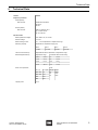
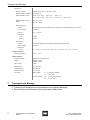
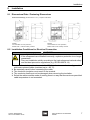
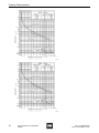
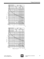
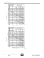
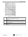
Operating Instructions Motor protection circuit-breaker > 8523/8 Contents 1 Contents 1 2 2.1 2.2 2.3 3 4 4.1 4.2 4.3 5 6 7 8 8.1 8.2 8.3 8.4 9 9.1 10 10.1 11 12 13 14 15 2 Contents ................................................................................................................2 General Information ...............................................................................................2 Manufacturer .........................................................................................................2 Operating Instructions Information ........................................................................2 Conformity to Standards and Regulations .............................................................2 Symbols Used .......................................................................................................3 General Safety Instructions ...................................................................................3 Operating Instructions Storage ..............................................................................3 Alterations and Modifications ................................................................................4 Special Versions ....................................................................................................4 Intended Use .........................................................................................................4 Technical Data ......................................................................................................5 Transport and Storage ..........................................................................................6 Installation .............................................................................................................7 Dimensional Data / Fastening Dimensions ...........................................................7 Installation Conditions for Electrical Connection ...................................................7 Installation Conditions for Electrical Connection Cross-Sections ..........................8 Back-up Fuses for Auxiliary Circuits ......................................................................9 Putting into Service ...............................................................................................9 Setting the Thermal Overcurrent Trip ..................................................................10 Maintenance, Overhaul and Repair .....................................................................10 Regular Maintenance Work .................................................................................11 Cleaning ..............................................................................................................11 Disposal ...............................................................................................................11 Accessories and Spare Parts ..............................................................................11 Tripping Characteristics .......................................................................................12 EC Declaration of Conformity ..............................................................................20 General Information 2.1 Manufacturer R. STAHL Schaltgeräte GmbH Am Bahnhof 30 74638 Waldenburg Germany Tel: Fax: Internet: +49 7942 943-0 +49 7942 943-4333 www.stahl-ex.com 2.2 Operating Instructions Information ID-No.: Publication Code: 146710 / 8523612300 2013-12-12·BA00·III·en·04 2.3 Conformity to Standards and Regulations Conformity with standards and regulations is specified in the corresponding certificates and the Manufacturer's Declaration (EC Declaration of Conformity). These documents can be downloaded from our homepage www.stahl-ex.com. 2 Motor protection circuit-breaker 8523/8 146710 / 8523612300 2013-12-12·BA00·III·en·04 Symbols Used 3 Symbols Used Safety Instructions Non-observance can result in damage to equipment, seriours injuries or death. The safety instructions contained in these operating instructions and affixed to the device must be observed! Warning symbol Danger due to explosive atmosphere! Warning symbol Danger due to live parts! 4 Note This graphic marks important additional information, tips and recommendations. General Safety Instructions 4.1 Operating Instructions Storage Read these operating instructions carefully and store them near the installation place. For correct operation, please observe all other documents enclosed in this delivery and the operating instructions of the equipment to be connected. WARNING Use the devices only for their intended purpose! We cannot be held liable for damage caused by incorrect or unauthorized use or by non-observance of these operating instructions. Use the device only if it is undamaged. WARNING Any unauthorized work on the device is prohibited! Installation, maintenance, overhaul and repair may only be carried out by appropriately authorized and trained personnel. Observe the following information during installation and operation: Any damage can invalidate the explosion protection National and local safety regulations National and local accident prevention regulations National and local assembly and installation regulations Generally recognized technical regulations Safety instructions in these operating instructions Characteristic values and rated operating conditions on the rating plates and data plates Additional information plates fixed directly to the device 146710 / 8523612300 2013-12-12·BA00·III·en·04 Motor protection circuit-breaker 8523/8 3 Intended Use 4.2 Alterations and Modifications WARNING Alterations and modifications to the device are not permitted! We shall not accept any liability or warranty obligations for damage resulting from alterations and modifications. 4.3 Special Versions In case of additional/different order options, special versions may differ from the description given here. 5 Intended Use The motor protection circuit breakers of Series 8523 are equipped with a non-adjustable fast short-circuit release and a thermal overcurrent release adjustable at the switch. They are used for protecting and switching explosion-protected electric motors. As "incomplete Ex equipment", they must be installed in a specially certified enclosure of type of protection "increased safety". The installation must be checked by a recognized expert. They are certified for use in hazardous areas of Zones 1 and 2. Special characteristics of the motor protection circuit breaker: Phase failure sensitivity according to IEC/EN 60947 Temperature compensation within the ambient temperature range Trip-free release Isolating characteristics Main switch and EMERGENCY-STOP characteristics in connection with the appropriate actuator X Can be fitted in any operating position X X X X X 4 Motor protection circuit-breaker 8523/8 146710 / 8523612300 2013-12-12·BA00·III·en·04 Technical Data 6 Technical Data Version 8523/8 Explosion protection Global (IECEx) Gas and dust IECEx BVS 08.0039 U Ex de IIC Ex de I Europe (ATEX) Gas and dust DMT 01 ATEX E 153 U E II 2 G Ex de IIC E I M 2 Ex de I Electrical data Rated operational voltage max. 690 V AC, 50 / 60 Hz Minimal voltage 12 V AC Rated working current 0.1 ... 22.5 A dependent on adjustment range Switching capacity dependent on adjustment range (AC) 230 V 400 V 500 V 690 V 7.0 kW 12.4 kW 16.0 kW 22.0 kW Thermal overcurrent trip Adjustable at switch; dependent on adjustment range Electromagnetic fast trip Adjustment range Threshold values set at factory 0.16 A ... 0.63 A 7.5 ... 12.0 In 1.0 A ... 2.5 A 9.0 ... 14.0 In 4.0 A ... 6.3 A 10.0 ... 15.0 In 9.0 A ... 22.5 A 12.5 ... 17.5 In Short circuit protection Fuse Ue (~V) AC-3 (kW) gG (A) IK (A) 220 / 230 7.0 380 / 400 12.5 Tripping class 146710 / 8523612300 2013-12-12·BA00·III·en·04 500 16.0 690 22.0 20 25 35 ) 300 ) 400 ) 650 10 A Motor protection circuit-breaker 8523/8 5 Transport and Storage Accessories Auxiliary contacts Options: none; 1 NC + 1 NO; 2 NC + 2 NO Rated operational voltage Ue max. 500 V AC Rated operational current AC 15: 24 V / 2.5 A 230 V / 2 A 400 V / 1 A DC 13: 24 V / 2.5 A 60 V / 2.5 A 110 V / 0.6 A Rated operational current at least 220 V / 0.25 A 24 V DC: 5 mA 12 V DC: 10 mA Undervoltage trip Function When power is lost, circuit-breaker trips; this prevents unwanted restarting, e.g. of a motor Pick-up voltage ≥ 0.85 x Uc Drop-out 0.7 ... 0.35 x Uc Power input Inrush 0.9 VA Holding 0.9 VA Shunt release Function For remote tripping of circuit-breakers by applying actuating voltage Pick-up voltage ≥ 0.85 x Uc Power input Inrush 24 ... 60 V: 14.4 ... 90 VA; 110 ... 240 V: 13 ... 61 VA; 220 ... 415 V: 17.6 ... 62.3 VA Ambient conditions Ambient temperature -20 °C ... +40 °C Mechanical data 7 Enclosure material Epoxy resin or polyester resin Weight 8523/81: 1400 g 8523/82: 1800 g Main contacts 3-pole Mechanical life 105 operations Impact strength to IEC 6068-2-6 Sine wave impact 15 g (11 ms) Connection Main contacts 1.5 ... 6 mm2 finely stranded 1.5 ... 10 mm2 solid Auxiliary contacts 0.75 ... 1.5 mm2 finely stranded 0.75 ... 2.5 mm2 solid Transport and Storage Transport and storage are only permitted in the original packaging. The devices must be stored in a dry place and vibration-free. 6 Motor protection circuit-breaker 8523/8 146710 / 8523612300 2013-12-12·BA00·III·en·04 Installation 8 Installation 8.1 Dimensional Data / Fastening Dimensions Dimensional Drawings (All Dimensions in mm ) - Subject to Alterations 04324E00 8523/81 Circuit-breaker for motor protection, Module width 1, without auxiliary contacts 04323E00 8523/82 Circuit-breaker for motor protection, Module width 2, with auxiliary contacts 8.2 Installation Conditions for Electrical Connection WARNING Incorrectly installed components! If the components are installed incorrectly, explosion protection is no longer guaranteed. Carry out installation strictly according to the instructions and national safety and accident prevention regulations (e.g. IEC/EN 60079-14). In case of a rated operational current of ≥ 15.5 A, a direct connection is only permitted with heat-resistant cables (resistant up to > 85 °C). Be especially careful when connecting the cable. The conductor insulation must reach to the terminal. The conductor itself must not be damaged when removing the insulation. Select the cables and the mode of running them in a way that the maximum permitted cable temperature is not exceeded. 146710 / 8523612300 2013-12-12·BA00·III·en·04 Motor protection circuit-breaker 8523/8 7 Installation Circuit-breaker connection diagram with connection references, options a), b), c) or d) and connections. 11530E00 11531E00 Single-phase AC and DC 3-phase AC Options: a) = Shunt trip b) = Undervoltage trip c) = Additional auxiliary switch d) = Additional auxiliary switch L1(1), L2(3), L3(5) T1(2), T2(4), T3(6) N = Phase (input) = Phase (output) = Neutral 8.3 Installation Conditions for Electrical Connection Cross-Sections WARNING Incorrectly installed components! Explosion protection cannot be guaranteed any more if the components are incorrectly installed. When terminal sleeves are fitted, they must be gas-tight and applied with a suitable tool. 1 or 2 cables may be connected to a single terminal. If the conductors are single-wire, both must have the same cross-section and be of the same material. Cables can be connected without any special preparation. Main contact terminals Auxiliary contact terminals 11532E00 single-wire 2 2 x 1.5 ... 10 mm 2 x AWG 16 to 8 11533E00 2 x 0.75 ... 1.5 mm 2 x AWG 18 to 13 2 2 13 11534E00 mm2 8 11535E00 fine- or multi-stranded 2 x 1.5 ... 6 2 x AWG 16 to 10 2 x 0.75 ... 1.5 mm 2 x AWG 18 to 16 permitted torques 1.8 ... 2.0 Nm 1 ... 1.2 Nm Motor protection circuit-breaker 8523/8 146710 / 8523612300 2013-12-12·BA00·III·en·04 Putting into Service 8.4 Back-up Fuses for Auxiliary Circuits As a general rule, auxiliary circuits must be protected by a 10 A gL fuse. Exception: An undervoltage trip is connected to the circuit-breaker main contact terminals. No back-up fuse is required. 09140E00 Types 8523/82 9 09029E00 Types 8523/81 Putting into Service WARNING Check the device before commissioning! To ensure the correct operation, check the device before commissioning. Before commissioning, ensure that: no components are damaged the device has been installed according to regulations there are no foreign bodies inside the device all screws and nuts have been firmly tightened the prescribed tightening torques have been observed connection has been made correctly 9.1 Setting the Thermal Overcurrent Trip WARNING Risk of explosion due to overheating of the motor! Risk of death or severe injuries! Set the thermal overcurrent release according to the technical data of the motor. 146710 / 8523612300 2013-12-12·BA00·III·en·04 Motor protection circuit-breaker 8523/8 9 Maintenance, Overhaul and Repair The required current value can be set by using a suitable screwdriver. The open end of the slot shows the set current value (see drawing for sample rated current of 6,3 A). 11478E00 NOTE If ambient temperatures differ from standard values, or between motor and circuit-breaker, the trip response must be checked – and the current setting changed if necessary. 10 Maintenance, Overhaul and Repair WARNING Risk due to unauthorized work being performed on the device! Risk of injury and damage to equipment. Assembly, installation, commissioning, operation and maintenance must only be carried out by appropriately authorized and trained personnel. WARNING Danger due to live parts! Risk of severe injuries. All connections and wiring must be disconnected from the power supply. Secure the connections against unauthorized switching. WARNING Short circuit in the circuit! After multiple short circuits in the circuit, the flameproof enclosure is no longer guaranteed. After a short circuit in the circuit, check the functionality of the device. Replace the entire device, if necessary. 10 Motor protection circuit-breaker 8523/8 146710 / 8523612300 2013-12-12·BA00·III·en·04 Cleaning 10.1 Regular Maintenance Work Consult the relevant national regulations (e.g. IEC/EN 60079-17) to determine the type and extent of inspections. Plan the intervals such that any expected defects in the equipment are detected promptly. To check as part of maintenance: Check if the cables are clamped properly. Inspect the device for signs of visible damage. Compliance with the permitted temperatures in accordance with IEC/EN 60079-0. Make sure that the device is used according to its designated use. Make sure the operating handle can be reset. 11 Cleaning Clean with a cloth, brush, vacuum cleaner or similar items. When cleaning with a damp cloth, use water or mild, non-abrasive, non-scratching cleaning agents. Never use aggressive cleaning agents or solvents. 12 Disposal Observe the national waste disposal regulations. 13 Accessories and Spare Parts WARNING If wrong accessories are used, explosion protection cannot be guaranteed! Use only original R. STAHL accessories and spare parts. Designation Illustration Description Art. no. Weight kg for undervoltage release, length 400 mm Jumper 147121 0.019 04951E00 146710 / 8523612300 2013-12-12·BA00·III·en·04 Motor protection circuit-breaker 8523/8 11 Tripping Characteristics 14 Tripping Characteristics The tripping characteristic curves refer to a 3-pole load from cold state at an ambient temperature of +20 °C and any position. The deviation of the tripping time (from a current three times higher than the rated current) is ±20 % maximum according to IEC/EN 60079-14. The following tripping characteristic curves show the tripping time as a function of the current ratio la/Ie. Legend: 1) Multiples of the rated current 2) Tripping time 3) 2-pole 4) 3-pole 5) Electromagnetic tripping 05930E00 12 Motor protection circuit-breaker 8523/8 146710 / 8523612300 2013-12-12·BA00·III·en·04 Tripping Characteristics 05931E00 05932E00 146710 / 8523612300 2013-12-12·BA00·III·en·04 Motor protection circuit-breaker 8523/8 13 Tripping Characteristics 05937E00 05938E00 14 Motor protection circuit-breaker 8523/8 146710 / 8523612300 2013-12-12·BA00·III·en·04 Tripping Characteristics 05939E00 05940E00 146710 / 8523612300 2013-12-12·BA00·III·en·04 Motor protection circuit-breaker 8523/8 15 Tripping Characteristics 05941E00 05942E00 16 Motor protection circuit-breaker 8523/8 146710 / 8523612300 2013-12-12·BA00·III·en·04 Tripping Characteristics 05943E00 05944E00 146710 / 8523612300 2013-12-12·BA00·III·en·04 Motor protection circuit-breaker 8523/8 17 Tripping Characteristics 05945E00 05946E00 18 Motor protection circuit-breaker 8523/8 146710 / 8523612300 2013-12-12·BA00·III·en·04 Tripping Characteristics 05947E00 Circuit-breakers (motor protection switches) for squirrel cage motors must be so selected that the tripping time with 3-pole loading is not greater than the warm-up time tE given on the machine test plate. (The tripping time should be taken from the IA/IN ratio curve of the machine to be protected.) The value for tripping time tA relative to the ratio of operating currents IA/IN should not only guarantee safe switch-off within the warm-up time (tA ≤ tE) but also still enable the motor to run up to speed safely when the trip is at operating temperaturte. IEC/EN 60079-7 specifies that the warm-up time tE shall not be shorter than 5 seconds. 146710 / 8523612300 2013-12-12·BA00·III·en·04 Motor protection circuit-breaker 8523/8 19