1
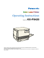
Operating Instructions
Model No.
KX-P8420
Please carefully read the Operating Instructions and the Drivers and Utilities Reference Guide before
operating. Keep this CD-ROM in the protective case.
Do not expose the CD-ROM to direct sunlight or extreme heat and do not scratch or smudge the surface of
the CD-ROM.
Thank you for purchasing the Panasonic KX-P8420 Color Laser Printer.
The serial number is located on the label on the rear of the unit. For your convenience, record the
number below and keep this book along with your proof of purchase, in the event of a theft or for future
reference.
MODEL NO.
KX-P8420
NAME OF RESELLER
2
SERIAL NO.
DATE OF PURCHASE
As an ENERGY STAR® Partner, Panasonic has determined that this product meets
the ENERGY STAR® guidelines for energy efficiency.
(ENERGY STAR is a U.S. registered mark.)
Adobe, Acrobat, Adobe Photoshop, Adobe Illustrator, PostScript, PostScript 3,
Adobe Type Manager and the PostScript 3 logo are trademarks of Adobe Systems
Incorporated.
Fiery, Fiery Driven and the Fiery Driven logo are trademarks owned by Electronics
for Imaging and registered with the U.S. Patent and Trademark Office and in certain
other foreign jurisdictions.
• Fiery WebTools, Fiery WebSpooler, Fiery WebLink, Fiery WebStatus, ColorWise and VisualCal are
trademarks of Electronics for Imaging, Inc.
• Apple, AppleTalk, LocalTalk, ColorSync, Macintosh, and TrueType are trademarks or registered trademarks
of Apple Computer, Inc.
• Ethernet is a trademark of Xerox Corporation.
• IBM is a trademark of International Business Machines Corporation.
• SunOS, Solaris and Java are trademarks or registered trademarks of Sun Microsystems, Inc. in the United
•
•
•
•
•
•
•
•
•
•
•
•
States and other countries.
QuarkXpress is a trademark of Quark, Inc.
CorelDRAW is a trademark of Corel Corporation.
Netscape and Netscape Navigator are trademarks of Netscape Communications Corporation.
NetWare, Novell and Internetwork Packet Exchange (IPX) are trademarks or registered trademarks of
Novell, Inc.
Times and Helvetica are trademarks of Linotype-Hell AG and/or its subsidiaries.
PANTONE is a trademark of Pantone, Inc.
UNIX is a trademark of X/Open Company, Ltd.
Microsoft, MS-DOS, Windows and Windows NT are registered trademarks of Microsoft Corporation in the
United States and/or other countries.
Pentium is a registered trademark of Intel Corporation.
Centronics is a trademark of Centronics Data Computer Corporation.
Avery is a registered trademark and all Avery codes are trademarks of Avery Dennison Corporation.
All other acknowledgements are trademarks or registered trademarks of their respective holders.
It is granted from Microsoft Corporation to use Microsoft® Windows® Screen Shots.
Acrobat® Reader copyright ©1987-1997 Adobe Systems Incorporated. All rights reserved.
The operating instructions are subject to change without notice.
© Electronics for Imaging, Inc. 1998
© Kyushu Matsushita Electric Co., Ltd. 1998
3
EFI STANDARD SOFTWARE LICENSE AGREEMENT
Electronics for Imaging, Inc. grants to you a non-exclusive, non-transferable license to use the software and
accompanying documentation (“Software”) included with the Fiery® server you have purchased, including
without limitation the PostScript® software provided by Adobe Systems Incorporated.
You may:
a. use the Software solely for your own customary business purposes and solely with the Fiery® server;
b. use the digitally-encoded machine-readable outline and bitmap programs (“Font Programs”) provided with
the Fiery® server in a special encrypted format (“Coded Font Programs”) to reproduce and display designs,
styles, weights, and versions of letters, numerals, characters and symbols (“Typefaces”) solely for your own
customary business purposes on the screen of the Fiery® server or Macintosh monitor used with the Fiery®
server;
c. use the trademarks used by Electronics for Imaging to identify the Coded Font Programs and Typefaces
reproduced therefrom (“Trademarks”); and
d. assign your rights under this Agreement to a transferee of all of your right, title and interest in and to the
Fiery® server provided the transferee agrees to be bound by all of the terms and conditions of this
Agreement.
You may not:
a. make use of the Software, directly or indirectly, to print bitmap images with print resolutions of 600 dots per
inch or greater, or to generate fonts or typefaces for use other than with the Fiery® server;
b. make or have made, or permit to be made, any copies of the Software, Coded Font Programs,
accompanying documentation or portions thereof, except as necessary for use with the Fiery® Server
purchased by you; provided, however, that under no circumstances may you make or have made, or permit
to be made, any copies of that certain portion of the Software which has been included on the Fiery® server
hard disk drive. You may not copy the documentation;
c. attempt to alter, disassemble, decrypt or reverse engineer the Software, Coded Font Programs or
accompanying documentation.
d. rent or lease the Software.
Proprietary Rights
You acknowledge that the Software, Coded Font Programs, Typefaces, Trademarks and accompanying
documentation are proprietary to Electronics for Imaging and its suppliers and that title and other intellectual
property rights therein remain with Electronics for Imaging and its suppliers. Except as stated above, this
Agreement does not grant you any right to patents, copyrights, trade secrets, trademarks (whether registered
or unregistered), or any other rights, franchises or licenses in respect of the Software, Coded Font Programs,
Typefaces, Trademarks or accompanying documentation. You may not adapt or use any trademark or trade
name which is likely to be similar to or confusing with that of Electronics for Imaging or any of its suppliers or
take any other action which impairs or reduces the trademark rights of Electronics for Imaging or its suppliers.
The trademarks may be used only to identify printed output produced by the Coded Font Programs. At the
reasonable request of Electronics for Imaging, you must supply samples of any Typeface identified with a
trademark. The MacApp software is proprietary to Apple Computer, Inc. and is licensed to Electronics for
Imaging, Inc. for distribution only for use in combination with Fiery® server software utilities.
Confidentiality
You agree to hold the Software and Coded Font Programs in confidence, disclosing the Software and Coded
Font Programs only to authorized users having a need to use the Software and Coded Font Programs as
permitted by this Agreement and to take all reasonable precautions to prevent disclosure to other parties.
4
Remedies
Unauthorized use, copying or disclosure of the Software, Coded Font Programs, Typefaces, Trademarks or
accompanying documentation will result in automatic termination of this license and will make available to
Electronics for Imaging other legal remedies.
Limited Warranty And Disclaimer
Electronics for Imaging warrants that, for a period of ninety (90) days from the date of delivery to you, the
Software under normal use will perform without significant errors that make it unusable. Electronics for
Imaging’s entire liability and your exclusive remedy under this warranty (which is subject to you returning Fiery
to Electronics for Imaging or an authorized dealer) will be, at Electronics for Imaging’s option, to use
reasonable commercial efforts to attempt to correct or work around errors, to replace the Software with
functionally equivalent software, or to refund the purchase price and terminate this Agreement. Some states do
not allow limitations on duration of implied warranty, so the above limitation may not apply to you.
Except for the above express limited warranty, Electronics for Imaging makes and you receive no warranties or
conditions on the Product, express, implied, or statutory, and Electronics for Imaging specifically disclaims any
implied warranty or condition of merchantability or fitness for a particular purpose.
For warranty service, please contact your authorized service/support center.
EXCEPT FOR THE ABOVE EXPRESS LIMITED WARRANTY, ELECTRONICS FOR IMAGING MAKES AND
YOU RECEIVE NO WARRANTIES OR CONDITIONS ON THE SOFTWARE OR CODED FONT
PROGRAMS, EXPRESS, IMPLIED, STATUTORY, OR IN ANY OTHER PROVISION OF THIS AGREEMENT
OR COMMUNICATION WITH YOU, AND ELECTRONICS FOR IMAGING SPECIFICALLY DISCLAIMS ANY
IMPLIED WARRANTY OR CONDITION OF MERCHANTABILITY OR FITNESS FOR A PARTICULAR
PURPOSE. Electronics for Imaging does not warrant that the operation of the software will be uninterrupted or
error free or that the Software will meet your specific requirements.
Limitation Of Liability
IN NO EVENT WILL ELECTRONICS FOR IMAGING OR ITS SUPPLIERS BE LIABLE FOR ANY DAMAGES,
INCLUDING LOSS OF DATA, LOST PROFITS, COST OF COVER OR OTHER SPECIAL, INCIDENTAL,
CONSEQUENTIAL OR INDIRECT DAMAGES ARISING FROM THE USE OF THE SOFTWARE, CODED
FONT PROGRAMS OR ACCOMPANYING DOCUMENTATION, HOWEVER CAUSED AND ON ANY
THEORY OF LIABILITY. THIS LIMITATION WILL APPLY EVEN IF ELECTRONICS FOR IMAGING OR ANY
AUTHORIZED DEALER HAS BEEN ADVISED OF THE POSSIBILITY OF SUCH DAMAGE. YOU
ACKNOWLEDGE THAT THE PRICE OF FIERY REFLECTS THIS ALLOCATION OF RISK. BECAUSE SOME
STATES/JURISDICTIONS DO NOT ALLOW THE EXCLUSION OR LIMITATION OF LIABILITY FOR
CONSEQUENTIAL OR INCIDENTAL DAMAGES, THE ABOVE LIMITATION MAY NOT APPLY TO YOU.
Export Controls
You agree that you will not export or re-export the Software or Coded Font Programs in any form without the
appropriate United States and foreign government licenses. Your failure to comply with this provision is a
material breach of this Agreement.
Government Use
Use, duplication or disclosure of the Software by the United States Government is subject to restrictions as set
forth in subdivision (c) (1) (ii) of the Rights in Technical Data and Computer Software clause at DFARS
252.227-7013 or in subparagraphs (c) (1) and (2) of the Commercial Computer Software—Restricted Right
Clause at 48 CFR 52.227-19, as applicable.
5
Third Party Beneficiary
You are hereby notified that Adobe Systems Incorporated, a California corporation located at 1585 Charleston
Road, Mountain View, California 94039-7900 (“Adobe”) is a third-party beneficiary to this Agreement to the
extent that this Agreement contains provisions which relate to your use of the Fonts, the Coded Font
Programs, the Typefaces and the Trademarks licensed hereby. Such provisions are made expressly for the
benefit of Adobe and are enforceable by Adobe in addition to Electronics for Imaging.
General
This Agreement will be governed by the laws of the State of California.
This Agreement is the entire agreement held between us and supersedes any other communications or
advertising with respect to the Software, Coded Font Programs and accompanying documentation.
If any provision of this Agreement is held invalid, the remainder of this Agreement shall continue in full force
and effect.
If you have any questions, please see Electronics for Imaging’s web site at www.efi.com.
6
FOR USERS IN UNITED STATES
Technical Support Calls
If you have read this manual and tried the troubleshooting procedures and you are still having difficulty,
please contact the reseller from which the unit was purchased. You may also call the end user technical
support telephone number which is operational during East Coast business hours (9:00 AM to 7:00 PM).
The end user technical support number is 1-888-744-2424.
This number is available within the U.S. only.
Helpful Phone Numbers
To locate your nearest sales dealer
To order consumables
To order operating instructions/CD’s
To locate your nearest authorized service center
For technical support
Automated 24-hour support via Fax back
Electronic bulletin board
World Wide Web Technical & Driver Support
CALL 1-800-742-8086 ask for COLOR
CALL 1-800-222-0584
CALL 1-800-833-9626
CALL 1-888-744-2424
CALL 1-888-744-2424
CALL 1-800-222-0584
CALL 1-201-863-7845
http://www.panasonic.com/alive
7
Contents
EFI STANDARD SOFTWARE LICENSE AGREEMENT . . . . . . . . . . . . . . .
4
For Your Safety . . . . . . . . . . . . . . . . . . . . . . . . . . . . . . . . . . . . . . . . . . . . . . 12
General . . . . . . . . . . . . . . . . . . . . . . . . . . . . . . . . . . . . . . . . . . . .
Power source . . . . . . . . . . . . . . . . . . . . . . . . . . . . . . . . . . . . . . .
Laser safety . . . . . . . . . . . . . . . . . . . . . . . . . . . . . . . . . . . . . . . .
Ozone release . . . . . . . . . . . . . . . . . . . . . . . . . . . . . . . . . . . . . .
Moving the unit . . . . . . . . . . . . . . . . . . . . . . . . . . . . . . . . . . . . .
Caution labels . . . . . . . . . . . . . . . . . . . . . . . . . . . . . . . . . . . . . .
12
12
12
12
13
14
Cautions . . . . . . . . . . . . . . . . . . . . . . . . . . . . . . . . . . . . . . . . . . . 16
Chapter 1
Before You
Start
CD-ROM . . . . . . . . . . . . . . . . . . . . . . . . . . . . . . . . . . . . . . . . . . . . . . . . . . 18
Static electricity damage . . . . . . . . . . . . . . . . . . . . . . . . . . . . . . . . . . . . . . 19
Waste disposal method . . . . . . . . . . . . . . . . . . . . . . . . . . . . . . . . . . . . . . . 19
Features of the KX-P8420 . . . . . . . . . . . . . . . . . . . . . . . . . . . . . 20
High quality . . . . . . . . . . . . . . . . . . . . . . . . . . . . . . . . . . . . . . . . . . . . . . . .
High speed . . . . . . . . . . . . . . . . . . . . . . . . . . . . . . . . . . . . . . . . . . . . . . . . .
Easy operation . . . . . . . . . . . . . . . . . . . . . . . . . . . . . . . . . . . . . . . . . . . . . .
Networking and client capabilities . . . . . . . . . . . . . . . . . . . . . . . . . . . . . . .
Color capabilities . . . . . . . . . . . . . . . . . . . . . . . . . . . . . . . . . . . . . . . . . . . .
Color management. . . . . . . . . . . . . . . . . . . . . . . . . . . . . . . . . . . . . . . . . . .
Fiery WebTools . . . . . . . . . . . . . . . . . . . . . . . . . . . . . . . . . . . . . . . . . . . . .
20
20
20
20
21
21
22
System requirements . . . . . . . . . . . . . . . . . . . . . . . . . . . . . . . . 23
With a Windows computer . . . . . . . . . . . . . . . . . . . . . . . . . . . . . . . . . . . . . 23
With a Macintosh computer . . . . . . . . . . . . . . . . . . . . . . . . . . . . . . . . . . . . 23
Minimum space requirements . . . . . . . . . . . . . . . . . . . . . . . . .
Power source . . . . . . . . . . . . . . . . . . . . . . . . . . . . . . . . . . . . . . .
Unpacking . . . . . . . . . . . . . . . . . . . . . . . . . . . . . . . . . . . . . . . . .
Part names . . . . . . . . . . . . . . . . . . . . . . . . . . . . . . . . . . . . . . . . .
24
24
25
26
Front side view . . . . . . . . . . . . . . . . . . . . . . . . . . . . . . . . . . . . . . . . . . . . . . 26
Rear side view . . . . . . . . . . . . . . . . . . . . . . . . . . . . . . . . . . . . . . . . . . . . . . 26
Front panel overview. . . . . . . . . . . . . . . . . . . . . . . . . . . . . . . . . 27
LCD (Liquid Crystal Display) panel . . . . . . . . . . . . . . . . . . . . . . . . . . . . . . 27
Activity lights . . . . . . . . . . . . . . . . . . . . . . . . . . . . . . . . . . . . . . . . . . . . . . . 27
Buttons . . . . . . . . . . . . . . . . . . . . . . . . . . . . . . . . . . . . . . . . . . . . . . . . . . . . 28
8
Contents
Setting up the printer . . . . . . . . . . . . . . . . . . . . . . . . . . . . . . . . 29
Chapter 2
Printer
Setup
Preparing the imaging unit . . . . . . . . . . . . . . . . . . . . . . . . . . . . . . . . . . . . .
Setting up the output tray . . . . . . . . . . . . . . . . . . . . . . . . . . . . . . . . . . . . . .
Installing the toner cartridges . . . . . . . . . . . . . . . . . . . . . . . . . . . . . . . . . . .
Loading media . . . . . . . . . . . . . . . . . . . . . . . . . . . . . . . . . . . . . . . . . . . . . .
Connecting the printer to a computer. . . . . . . . . . . . . . . . . . . . . . . . . . . . .
Using a parallel interface cable . . . . . . . . . . . . . . . . . . . . . . . . . . . . . . . . .
Power on . . . . . . . . . . . . . . . . . . . . . . . . . . . . . . . . . . . . . . . . . . . . . . . . . .
Margins and print area . . . . . . . . . . . . . . . . . . . . . . . . . . . . . . . . . . . . . . . .
Loading media in the multi-purpose tray . . . . . . . . . . . . . . . . . . . . . . . . . .
29
30
31
33
35
36
37
38
39
Using the front panel. . . . . . . . . . . . . . . . . . . . . . . . . . . . . . . . . 44
Status messages . . . . . . . . . . . . . . . . . . . . . . . . . . . . . . . . . . . . . . . . . . . .
Error messages . . . . . . . . . . . . . . . . . . . . . . . . . . . . . . . . . . . . . . . . . . . . .
Top-level menus. . . . . . . . . . . . . . . . . . . . . . . . . . . . . . . . . . . . . . . . . . . . .
Printing pages from the front panel . . . . . . . . . . . . . . . . . . . . . . . . . . . . . .
Chapter 3
Connecting
the Printer
to a Network
44
45
45
47
Network connections . . . . . . . . . . . . . . . . . . . . . . . . . . . . . . . . 49
Ethernet network connections . . . . . . . . . . . . . . . . . . . . . . . . . . . . . . . . . . 49
Token Ring network connections . . . . . . . . . . . . . . . . . . . . . . . . . . . . . . . . 51
Parallel cable connection . . . . . . . . . . . . . . . . . . . . . . . . . . . . . 52
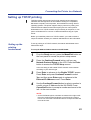
Setting up TCP/IP printing . . . . . . . . . . . . . . . . . . . . . . . . . . . . 53
Setting up the printing environment . . . . . . . . . . . . . . . . . . . . . . . . . . . . . .
UNIX server print queues. . . . . . . . . . . . . . . . . . . . . . . . . . . . . . . . . . . . . .
Verifying the TCP/IP network connection. . . . . . . . . . . . . . . . . . . . . . . . . .
Setting up TCP/IP clients for printing . . . . . . . . . . . . . . . . . . . . . . . . . . . . .
Setting up TCP/IP clients for running Fiery WebTools. . . . . . . . . . . . . . . .
Printing and administering print jobs . . . . . . . . . . . . . . . . . . . . . . . . . . . . .
53
55
58
59
59
60
Setting up IPX (Novell) printing . . . . . . . . . . . . . . . . . . . . . . . . 61
Overview of IPX printing to the KX-P8420 . . . . . . . . . . . . . . . . . . . . . . . . .
Configuring the NetWare server. . . . . . . . . . . . . . . . . . . . . . . . . . . . . . . . .
Setting up a KX-P8420 print queue . . . . . . . . . . . . . . . . . . . . . . . . . . . . . .
Setting up NetWare Windows clients . . . . . . . . . . . . . . . . . . . . . . . . . . . . .
61
62
66
69
Using AppleTalk with Macintosh computers
on an IPX (Novell) network . . . . . . . . . . . . . . . . . . . . . . . . . .
Setting up Fiery WebTools . . . . . . . . . . . . . . . . . . . . . . . . . . . .
Setting up Windows 95 clients for SMB printing . . . . . . . . . .
Setting up Windows NT 4.0 clients for SMB printing. . . . . . .
69
70
73
76
9
Contents
Chapter 4
Installing
Software for
Windows
General steps. . . . . . . . . . . . . . . . . . . . . . . . . . . . . . . . . . . . . . . 77
Installing the PostScript printer driver for Windows . . . . . . . 78
Installing the PostScript printer driver for Windows 95. . . . . . . . . . . . . . . .
Specifying installed devices . . . . . . . . . . . . . . . . . . . . . . . . . . . . . . . . . . . .
Completing the connection for Windows 95. . . . . . . . . . . . . . . . . . . . . . . .
Setting up PostScript printing with Windows NT 4.0 . . . . . . . . . . . . . . . . .
Installing the PostScript printer driver for Windows NT 4.0 . . . . . . . . . . . .
Specifying installed devices . . . . . . . . . . . . . . . . . . . . . . . . . . . . . . . . . . . .
Completing the connection for Windows NT 4.0 . . . . . . . . . . . . . . . . . . . .
Installing the PostScript printer driver for Windows 3.1 . . . . . . . . . . . . . . .
Specifying installed devices . . . . . . . . . . . . . . . . . . . . . . . . . . . . . . . . . . . .
Completing the connection for Windows 3.1 . . . . . . . . . . . . . . . . . . . . . . .
78
79
80
82
83
84
85
89
90
91
Installing additional software for Windows users . . . . . . . . . 94
PostScript and TrueType fonts. . . . . . . . . . . . . . . . . . . . . . . . . . . . . . . . . . 94
ATM (Windows 95 and Windows 3.1) . . . . . . . . . . . . . . . . . . . . . . . . . . . . 94
Color reference pages . . . . . . . . . . . . . . . . . . . . . . . . . . . . . . . . . . . . . . . . 96
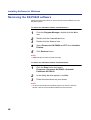
Removing the KX-P8420 software . . . . . . . . . . . . . . . . . . . . . . 98
Chapter 5
Installing
Macintosh
Software
Chapter 6
Setup from
the Front
Panel and
WebSetup
General steps for installing Macintosh software . . . . . . . . . . 100
Installing Macintosh printing software . . . . . . . . . . . . . . . . . . 101
Installing the Adobe PostScript printer driver . . . . . . . . . . . . . . . . . . . . . . . 101
Setting up the KX-P8420 in the Chooser . . . . . . . . . . . . . . . . . . . . . . . . . . 102
Installing the KX-P8420 ColorSync profile . . . . . . . . . . . . . . . . . . . . . . . . . 103
Installing additional software for Macintosh users . . . . . . . . 105
Adobe Type Manager. . . . . . . . . . . . . . . . . . . . . . . . . . . . . . . . . . . . . . . . . 105
PostScript and TrueType fonts. . . . . . . . . . . . . . . . . . . . . . . . . . . . . . . . . . 105
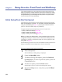
Initial Setup from the front panel . . . . . . . . . . . . . . . . . . . . . . . 106
ENERGY STAR®. . . . . . . . . . . . . . . . . . . . . . . . . . . . . . . . . . . . . . . . . . . . . .
Parallel Port Setup . . . . . . . . . . . . . . . . . . . . . . . . . . . . . . . . . . . . . . . . . . .
Network Port Setup . . . . . . . . . . . . . . . . . . . . . . . . . . . . . . . . . . . . . . . . . .
Network Protocol Setup . . . . . . . . . . . . . . . . . . . . . . . . . . . . . . . . . . . . . . .
Language Setup. . . . . . . . . . . . . . . . . . . . . . . . . . . . . . . . . . . . . . . . . . . . .
Reset Queues . . . . . . . . . . . . . . . . . . . . . . . . . . . . . . . . . . . . . . . . . . . . . .
Hard Disk . . . . . . . . . . . . . . . . . . . . . . . . . . . . . . . . . . . . . . . . . . . . . . . . . .
107
107
107
109
111
111
111
Completing setup from Fiery WebSetup . . . . . . . . . . . . . . . . . 112
Accessing Fiery WebSetup . . . . . . . . . . . . . . . . . . . . . . . . . . . . . . . . . . . .
System Setup. . . . . . . . . . . . . . . . . . . . . . . . . . . . . . . . . . . . . . . . . . . . . . .
Network Setup . . . . . . . . . . . . . . . . . . . . . . . . . . . . . . . . . . . . . . . . . . . . . .
Printer Setup . . . . . . . . . . . . . . . . . . . . . . . . . . . . . . . . . . . . . . . . . . . . . . .
Saving your settings and exiting Fiery WebSetup . . . . . . . . . . . . . . . . . . .
10
112
114
116
126
127
Contents
Chapter 7
Color
Calibration
Chapter 8
Care and
Maintenance
Bias adjustment. . . . . . . . . . . . . . . . . . . . . . . . . . . . . . . . . . . . . 129
VisualCal, 30% match calibration . . . . . . . . . . . . . . . . . . . . . . 134
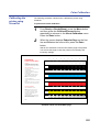
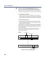
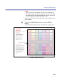
Calibrating the printer using VisualCal . . . . . . . . . . . . . . . . . . . . . . . . . . . . 135
Resetting the VisualCal calibration . . . . . . . . . . . . . . . . . . . . . . . . . . . . . . 140
Color adjustment . . . . . . . . . . . . . . . . . . . . . . . . . . . . . . . . . . . . 141
Resetting the Color adjustment . . . . . . . . . . . . . . . . . . . . . . . . . . . . . . . . . 143
Cleaning . . . . . . . . . . . . . . . . . . . . . . . . . . . . . . . . . . . . . . . . . . . 144
User replaceable components . . . . . . . . . . . . . . . . . . . . . . . . . 149
Displaying the life of supplies and coverage of toner . . . . . . 152
Maintenance. . . . . . . . . . . . . . . . . . . . . . . . . . . . . . . . . . . . . . . . . . . . . . . . 152
Image Area. . . . . . . . . . . . . . . . . . . . . . . . . . . . . . . . . . . . . . . . . . . . . . . . . 153
Clearing media jams . . . . . . . . . . . . . . . . . . . . . . . . . . . . . . . . . 153
Troubleshooting . . . . . . . . . . . . . . . . . . . . . . . . . . . . . . . . . . . . 167
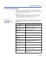
Front Panel Messages. . . . . . . . . . . . . . . . . . . . . . . . . . . . . . . . 177
Front panel status and error messages . . . . . . . . . . . . . . . . . . . . . . . . . . . 177
Front panel service calls . . . . . . . . . . . . . . . . . . . . . . . . . . . . . . . . . . . . . . 183
Repacking . . . . . . . . . . . . . . . . . . . . . . . . . . . . . . . . . . . . . . . . . 184
Chapter 9
Options
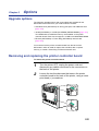
Upgrade options . . . . . . . . . . . . . . . . . . . . . . . . . . . . . . . . . . . . 193
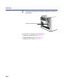
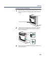
Removing and replacing the printer controller board . . . . . . 193
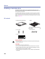
Installing a hard disk drive . . . . . . . . . . . . . . . . . . . . . . . . . . . . 196
Kit contents . . . . . . . . . . . . . . . . . . . . . . . . . . . . . . . . . . . . . . . . . . . . . . . . 196
Initializing the hard disk . . . . . . . . . . . . . . . . . . . . . . . . . . . . . . . . . . . . . . . 199
Installing additional memory . . . . . . . . . . . . . . . . . . . . . . . . . . 199
Kit contents . . . . . . . . . . . . . . . . . . . . . . . . . . . . . . . . . . . . . . . . . . . . . . . . 199
Installing SDRAM DIMMs. . . . . . . . . . . . . . . . . . . . . . . . . . . . . . . . . . . . . . 200
Installing network cards . . . . . . . . . . . . . . . . . . . . . . . . . . . . . . 202
Kit contents . . . . . . . . . . . . . . . . . . . . . . . . . . . . . . . . . . . . . . . . . . . . . . . . 202
Appendix
Specifications . . . . . . . . . . . . . . . . . . . . . . . . . . . . . . . . . . . . . . 205
Printer. . . . . . . . . . . . . . . . . . . . . . . . . . . . . . . . . . . . . . . . . . . . . . . . . . . . .
Media . . . . . . . . . . . . . . . . . . . . . . . . . . . . . . . . . . . . . . . . . . . . . . . . . . . . .
Bidirectional Parallel Interface . . . . . . . . . . . . . . . . . . . . . . . . . . . . . . . . . .
Controller . . . . . . . . . . . . . . . . . . . . . . . . . . . . . . . . . . . . . . . . . . . . . . . . . .
205
206
213
214
Index . . . . . . . . . . . . . . . . . . . . . . . . . . . . . . . . . . . . . . . . . . . . . . . . . . . . . . . . . . . . . . . . . 215
11
For Your Safety
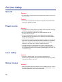
General
Warning
• To prevent fire or shock hazard, do not expose this product to rain or any
type of moisture.
Caution
• Do not open covers and do not attempt to repair the unit yourself. Refer
servicing to qualified personnel.
Power source
Warning
• The power source voltage of this unit is listed on the nameplate. Only plug
the unit into an outlet with the proper voltage.
• When you operate this equipment, the outlet should be near the
equipment and accessible.
• To ensure safe operation the AC cord supplied must be inserted into
standard three-prong AC outlet which is effectively grounded (earthed)
through the normal wiring.
• The fact that the equipment operates satisfactorily does not imply that the
power point is grounded (earthed) and that the installation is completely
safe. For your safety, if in any doubt about the effective grounding
(earthing) of the power point, consult a qualified electrician.
• If the plug cannot be inserted into the AC outlet, contact a licensed
electrician to replace the outlet with a properly grounded (earthed) one.
Do not defeat the purpose of the grounding (earthing) plug (ex. do not use
a conversion plug).
Laser safety
Caution
• This printer utilizes a laser. Use of controls or adjustments or
performance of procedures other than those specified herein may result
in hazardous radiation exposure.
Ozone release
Warning
• Make sure that the printer is installed in a well ventilated room so as not to
increase density of ozone in the air. Since ozone is heavier than air, it is
recommended that air at floor level be ventilated.
12
For Your Safety
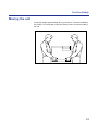
Moving the unit
The printer weighs approximately 48.2 kg {106.2 lbs.}. It must be handled by
two people. Turn the power off and remove the power cord when handling
the unit.
13
For Your Safety
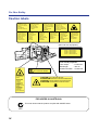
Caution labels
DANGER:
Invisible laser radiation
when open and interlock
defeated.
AVOID DIRECT
EXPOSURE TO BEAM.
PELIGRO:
Cuando se abre y se
invalida el bloqueo, se
producen radiaciones
invisibles de láser.
EVÍTESE LA
EXPOSICIÓN
A TALES RAYOS.
CAUTION:
Invisible laser radiation
when open and
interlocks defeated.
AVOID EXPOSURE
TO BEAM.
VARNING:
Osynlig laserstrålning när denna
del är öppnad och
spärrar är
urkopplade.
STRÅLEN
ÄR FARLIG.
VORSICHT:
Unsichtbare Laserstrahlung,
wenn Abdeckung geöffnet
und Sicherheitsverriegelung
überbrückt.
NICHT DEM STRAHL
AUSSETZEN.
VARO!:
Näkymätöntä
avattaessa ja
suojalukitus
ohitettaessa olet
alttiina lasersäteilylle.
ÄLÄ KATSO
SÄTEESEEN.
ATTENTION:
Rayonnement laser invisible
dangereux en cas
d'ouverture et lorsque
la sécurité est neutralisée.
EXPOSITION DANGEREUSE
AU FAISCEAU.
VARNING:
Osynlig laserstrålning
när denna del är
öppnad och spärren är
urkopplad.
BETRAKTA EJ
STRÅLEN.
ADVARSEL:
Usynlig laserstråling
ved åbning når
sikkerhedsafbrydere
er ude af funktion.
UNDGÅ
UDSÆTTELSE FOR
STRÅLING.
ADVARSEL:
Usynlig laserstråling
når deksel åpnes og
sikkerhedslas brytes.
UNNGÅ
EKSPONERING
FOR STRÅLEN.
(220–240 VAC equipment)
CLASS 1 LASER PRODUCT
KLASSE 1 LASER PRODUKT
CLASSE 1 LASER PRODUIT
CLASE 1 LÁSER PRODUCTO
CAUTION:
HOT SURFACE INSIDE
Laser diode properties
Laser output
: 5 mW max
Wavelength
: 780 nm
Emission duration : Continuous
CAUTION:
HOT SURFACE
INSIDE
ATTENTION:
SURFACE
CHAUDE
CI-INTERIEUR
CAUTION:HOT SURFACE BELOW
ATTENTION:SURFACE CHAUDE CI-DESSOUS
VORSICHT:HEIßE OBERFLÄCHE DARUNTER
ATENCION:SUPERFICIE CALIENTE ABAJO
VORSICHT:
HEISSE FLÄCHE
INTERN
ATENCION:
SUPERFICIE
CALIENTE
EN EL INTERNO
FOR USERS IN AUSTRALIA
This mark shows that the product complies with AS/NZS 3548.
N52
14
For Your Safety
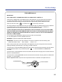
FOR USERS IN U.K.
IMPORTANT:
FOR YOUR SAFETY PLEASE READ THE FOLLOWING TEXT CAREFULLY
This printer is supplied with a moulded three pin mains plug each for your safety and convenience.
A 13 amp fuse is fitted in this plug. Should the fuse need to be replaced please ensure that the
replacement fuse has a rating of 13 amps and that it is approved by ASTA or BSI to BS 1362.
Check for the ASTA mark
ASA
or the BSI mark
on the body of the fuse.
If the plug contains a removable fuse cover you must ensure that it is refitted when the fuse is replaced.
If you lose the fuse cover the plug must not be used until a replacement cover is obtained. A
replacement fuse cover can be purchased from your local Panasonic Dealer.
IF THE FITTED MOULDED PLUG IS UNSUITABLE FOR THE SOCKET OUTLET IN YOUR HOME
THEN THE FUSE SHOULD BE REMOVED AND THE PLUG CUT OFF AND DISPOSED OF SAFELY.
THERE IS A DANGER OF SEVERE ELECTRICAL SHOCK IF THE CUT OFF PLUG IS INSERTED
INTO ANY 13 AMP SOCKET.
If a new plug is to be fitted please observe the wiring code as shown below.
If in any doubt please consult a qualified electrician.
WARNING: THIS APPLIANCE MUST BE EARTHED.
IMPORTANT: The wires in this mains lead are coloured in accordance with the following code.
Green-and-Yellow: Earth
Blue: Neutral
Brown: Live
As the colours of the wire in the mains lead of this appliance may not correspond with the coloured
markings identifying the terminals in your plug, proceed as follows.
The wire which is coloured GREEN-AND-YELLOW must be connected to the terminal in the plug which
is marked with the letter E or by the Earth symbol
, or coloured GREEN or GREEN-ANDYELLOW.
The wire which is coloured BLUE must be connected to the terminal in the plug which is marked with the
letter N or coloured BLACK.
The wire which is coloured BROWN must be connected to the terminal in the plug which is marked with
the letter L or coloured RED.
How to replace the fuse: Open the fuse compartment with a screwdriver and replace the fuse.
SCREWDRIVER
FUSE COVER
L
N
FUSE
15
Chapter 1
Before You Start
Before you set up your new printer, please read the following information.
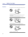
Cautions
To avoid problems, do not use the equipment under the following conditions:
• Direct exposure to sunlight
• Extremely high or low temperature [temperature range: 10˚C to 32.5˚C
(50˚F to 90.5˚F)]
• Extremely high or low humidity (humidity range: 20% to 80% RH)
• Condensation due to rapid change of temperature
• Areas of poor ventilation
• Areas of high dust or chemical fume concentration (solvent etc.)
• Unstable or unlevel surfaces
16
Before You Start
• Directly in front of air conditioning vents
• Liquids near the equipment
• Too much media/document which exceeds the limit mark on the guide of
the tray.
• Front/right/left doors opened while the printer is operating; it may cause a
media jam.
Not genuine toner
• Any toner other than genuine Panasonic toner. It may damage the printer.
17
Before You Start
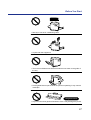
CD-ROM
To prevent accidental damage to the CD-ROMs:
• Do not touch or write on the surface of the disc.
• Do not leave the disc out of the protective case.
• Do not leave the disc in direct sunlight or near heat sources.
• Do not place heavy objects on the disc case or drop the case.
• To clean the disc, hold the disc by its edges and wipe it from the center to
the edges with a dry, soft cloth.
18
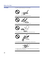
Before You Start
Static electricity
damage
To prevent static electricity damage to any of the following components,
touch a grounded metal surface, such as the printer’s bare metal frame prior
to touching the component.
• The interface connectors—parallel and optional network
• Electrical components, connectors inside the printer, any components on
the optional board (hard disk drive, SDRAM DIMMs, Ethernet network
card, or Token Ring network card)
• The connector pins on the optional 2nd cassette feeder for the printer
Waste disposal
method
Waste material may be dumped or incinerated under conditions which meet
all federal, state and local environmental regulations.
19
Before You Start
Features of the KX-P8420
The KX-P8420 Color Printer provides fast, high-quality color printing on
plain paper, plus the ease of operation and high performance you expect
from a laser printer, including the following.
High quality
• Resolution—maximum 1200 x 1200 dpi (with optional additional memory)
High speed
• Continuous printing on Letter or A4 size paper
Easy operation
• Printer driver—easily prints full-color documents
Networking and
client capabilities
• Supports AppleTalk (EtherTalk), TCP/IP, and IPX (Novell) protocols
Full-color mode—Maximum 3.5 ppm (pages per minute)
Three color mode—Maximum 4.7 ppm
Monochrome mode—Maximum 14 ppm
simultaneously by installing optional Ethernet Card
• Supports thicknet, twisted pair, and thinnet (via transceiver) cabling
• Ethernet or Token Ring support by installing optional Ethernet or Token
Ring Card
• SMB (Microsoft®)
• IEEE 1284 compliant, Mini-Centronics type-C parallel connection based
on the IEEE P1284-C standard
NOTE:
• An ECP compatible parallel port is recommended for Windows® 95*1. To
turn on the ECP mode, use the computer’s BIOS setup. Refer to the
computer’s documentation for details.
*1 Microsoft® Windows® 95 operating system (hereafter Windows 95)
20
Before You Start
Color capabilities
ColorWise™ CRDs (color rendering dictionaries) take full advantage of the
colors available on your printer. PostScript 3 RGB files are converted to the
printer’s CMYK color space during processing—optimizing them for
rendering and printing. CRDs available with the PostScript driver include:
• Photographic
• Presentation
• Transparency
Using the PostScript driver an image’s RGB data can be also converted to
the color space and gamut of the KX-P8420 printer using RGB source
profiles. Profiles available include:
• EFIRGB
• sRGB (PC)
• Apple Standard
In addition, CMYK simulation settings can be used to simulate popular
offset printing press standards. Simulation settings include:
• SWOP
• Euroscale
• DIC
Color management
ColorWise VisualCal™ allows experienced users to calibrate the KX-P8420
for excellent color output—eliminating out-of-calibration color most printers
experience over time.
ColorWise Color Adjustment provides controls for globally modifying toner
density and brightness.
ColorWise Business Color specifies the application of toner using a
diffusion dither pattern, which is ideal for color fills and blends commonly
found in charts and graphs used in business applications.
21
Before You Start
Fiery WebTools
Fiery WebTools are utilities that enable users to manage the KX-P8420
from the Internet or your company’s intranet:
•
•
•
•
•
Fiery WebDownloader
Status
Fiery WebSetup
Fiery WebLink
Fiery WebSpooler
For additional information on KX-P8420 specifications, see “Specifications”
on page 205.
The icons in this document indicate:
: Features and functionality which require an optional hard disk drive.
See “Installing a hard disk drive” on page 196.
32
: Features and functionality which require a minimum of 32 MB of SDRAM.
See “Installing additional memory” on page 199.
: Features and functionality available to printers operating in a networked environment.
See “Installing network cards” on page 202.
22
Before You Start
System requirements
You can use the printer in a networked environment and print from a PC
compatible computer running Windows or from a Macintosh computer.
With a Windows
computer
The minimum hardware configuration required to use the printer with an
IBM PC or compatible includes:
•
•
•
•
•
An IBM PC or compatible computer with a 386 processor or higher
A mouse that is supported by Windows
Windows 3.1*1, Windows 95 or Windows NT® 4.0*2*3 (Intel version)
Appropriate interface cables for your network or printer connection
Screen resolution more than or equal to 800 x 600 dpi to use Fiery
WebTools
• Screen color more than 256 color to use Fiery WebTools
With a Macintosh
computer
The minimum hardware configuration required to use the printer with a
Macintosh computer is:
• Any Macintosh computer in the Macintosh II, Quadra, Centris, Performa,
or Power Macintosh families with EtherTalk Phase 2 installed
• Apple system software version 7.5.x, 7.6.x or 8.0
• Appropriate interface cables for your network and printer connection.
• Ethernet Card (page 202)
It does not enable to connect KX-P8420 to Macintosh computer directly.
The data is printed through the Ethernet Card installed in the KX-P8420.
*1 Microsoft® Windows® operating system Version 3.1 (hereafter Windows
3.1)
*2 Microsoft® Windows NT® Workstation operating system, and Microsoft®
Windows NT® Server network operating system Version 4.0 (hereafter
Windows NT 4.0)
*3 Service Pack 3 or later version is required.
23
Before You Start
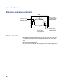
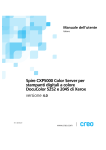
Minimum space requirements
Rear
35 cm (13.8")
Controller board
opening space
45 cm (17.7")
Multi-purpose tray
opening space
Right
Left
60 cm (23.6")
Front cover
opening space
50 cm (19.7")
Media tray
opening space
Power source
• The voltage level of the power source must not vary more than ±10% from
the voltage level marked on the nameplate (located on the back of the
unit).
• Do not use an extension cord.
• Do not use a line conditioner, transient suppressor or surge protector as it
may cause a machine error.
24
Before You Start
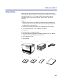
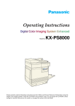
Unpacking
Make sure that all of the items shown below were provided and have not
been damaged. Report damage or shortages to the reseller from which the
unit was purchased. Page 2 includes an area for recording important
information such as the name of reseller, serial number, and date of
purchase.
NOTE:
• Save the original carton and packing materials for future shipping and
transporting of the unit. They have been specifically designed to protect
the equipment during shipment.
1. Printer (Color imaging unit, Fuser unit and Media tray are included.)
2. Toner cartridges (black, cyan, magenta, and yellow)
3. Power cord
4. KX-P8420 Driver & Utility CD-ROM
5. KX-P8420 Operating Manuals CD-ROM (includes Drivers and Utilities
Reference Guide and Operating Instructions)
6. Color Calibration Card
7. Setup Manual
1
4
2
5
3
6
7
25
Before You Start
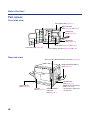
Part names
Front side view
Front panel (See page 27.)
Right side door
(See pages 32 and 165.)
Output tray
(See page 30.)
Media tray
(See page 33.)
Fuser (See pages 150 and 158.)
Front door (See page 29.)
Color imaging unit (See pages 29 and 149.)
Rear side view
Slot cover for optional Network card (See page 203.)
Multi-purpose tray (MPT)
(See page 43.)
Left side door
(See page 39.)
[Media thickness switch*
(See page 39.)]
Power switch
(See page 37.)
AC inlet
(See page 36.)
26
Parallel interface
connector
(See page 36.)
*Accessible by opening the
left side door
Before You Start
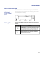
Front panel overview
This section describes the functions of the front panel, illustrated below:
LCD (Liquid
Crystal Display)
panel
The printer LCD has two 24-character lines to display the printer’s status/
error messages or menu settings.
READY
ERROR
MENU
/EXIT
ENTER
CANCEL
Activity lights
CONTINUE
The activity lights indicate the status of the printer. They have the following
meanings:
This light
READY
ERROR
Indicates
Ready indicator—Lit when the printer is on-line (ready
to accept and process new jobs), blinking when in menu
mode and when receiving, processing or printing data,
and off when the printer is off-line or the power is off.
Error indicator—Blinking when the printer requires
operator intervention (e.g., load paper); or lit when the
printer requires a service call.
27
Before You Start
Buttons
The front panel’s buttons have the following meanings:
This button
MENU
/EXIT
CANCEL
CONTINUE
ENTER
28
Indicates
Menu/Exit button—From Ready (or Sleep), enters
Menu mode. From Menu mode, exits menus entirely,
returning to Ready.
Cancel/Left button—While printing, Cancel stops
printing or processing the current job. In Menu mode,
returns to the previous menu item. When entering
numbers, decrements to the next number or moves the
cursor to the left.
Continue/Forward button—Advances to the next
selection in menu mode. When entering numbers,
increments to the next number. When using the Semi
Automatic Duplexing function in the printer driver, after
odd pages are printed, even pages are printed by
pressing this key.
Enter button—Accepts an option and advances to the
next choice in menu mode.
Chapter 2
Printer Setup
This chapter describes setting up the KX-P8420 Color Printer, connecting it
to a PC compatible computer, and powering on the printer. It also includes
print area specifications, guidelines for using the multi-purpose tray (MPT),
and instructions on using the front panel.
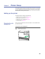
Setting up the printer
The general steps for setting up the printer are:
•
•
•
•
Preparing the color
imaging unit
“Preparing the color imaging unit” on page 29
“Setting up the output tray” on page 30
“Installing the toner cartridges” on page 31
“Loading media” on page 33
After you have unpacked the printer and located it on a flat, stable surface,
you need to set it up.
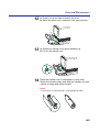
To prepare the color imaging unit:
1
Open the front door.
29
Printer Setup
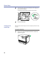
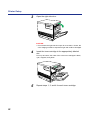
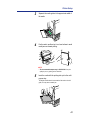
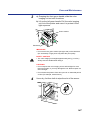
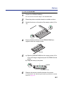
2
Turn the upper green lever clockwise until it stops and
the arrows are aligned.
This tightens the internal belts to ready the unit for printing.
3
Setting up the
output tray
Close the front door.
Make sure that you have enough room for the output tray and that it is easy
to access.
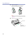
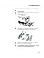
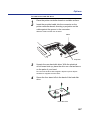
To set up the output tray:
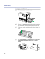
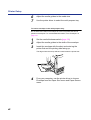
1
30
Remove the adhesive tape that holds the output tray
against the printer.
Printer Setup
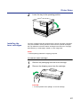
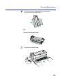
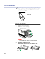
2
Installing the
toner cartridges
Lower the tray to the operating position.
The toner cartridges that are shipped with the printer are starter cartridges.
They are installed in exactly the same manner as the optional cartridges;
the only difference is that the starter cartridges have less toner. The page
life expectancy is 3,000 pages, based on a 5% image area.
NOTE:
• Save all packing material for shipping purposes.
To install the starter cartridges:
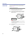
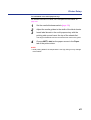
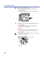
1
2
Remove the packaging from the toner cartridge.
Remove the shipping cover from the cartridge.
CAUTION:
• To avoid possible toner spillage, do not tilt cartridge.
31
Printer Setup
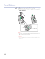
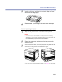
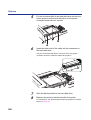
3
Open the right side door.
CAUTION:
• Do not leave the right side door open for more than 1 minute; the
color imaging unit will be exposed to light and could be damaged.
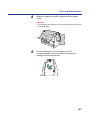
4
Insert the toner cartridge in the appropriately labeled
slot.
From top to bottom, the order of the color toner cartridges is black,
cyan, magenta, and yellow.
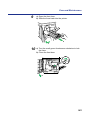
5
32
Repeat steps 1, 2, and 4 for each toner cartridge.
Printer Setup
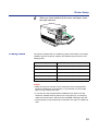
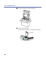
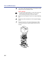
6
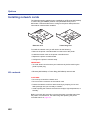
Loading media
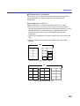
When you have installed all the toner cartridges, close
the right side door.
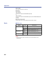
The printer is shipped with one media tray (either Letter Paper or A4 Paper)
installed, however the printer supports five different trays as shown in the
following table.
Tray
Size
A4 Paper
210 mm x 297 mm (8.3" x 11.7")
A4 Transparency
210 mm x 297 mm (8.3" x 11.7")
Letter Paper
216 mm x 279 mm (8.5" x 11")
Letter Transparency
216 mm x 279 mm (8.5" x 11")
Legal Paper
216 mm x 356 mm (8.5" x 14")
NOTES:
• Make sure that you load the correct media. Each tray is designed and
labeled for only paper or transparency. If you load the incorrect media
type in a tray, it may cause a jam.
• If you have the 2nd cassette feeder installed and you wish to use the
automatic cassette-switching feature (for a large print job, for example),
make sure that all trays in the printer are the same media type and size.
• The transparency tray should only be inserted in the upper or middle tray
slots.
33
Printer Setup
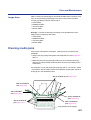
To load paper or transparencies:
34
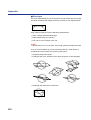
1
Pull the media tray out of the printer.
2
Remove all packaging materials from inside the media
tray; refer to the instruction sheet attached to the tray.
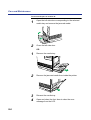
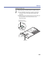
3
Push down on the metal plate until it clicks, locking it in
place.
4
Fan the media (paper or transparencies), and then tap it
on a level surface to avoid media jams or skewed
printing.
Printer Setup
NOTES:
• To optimize your printer’s performance, always use clean,
unused media.
• Be careful not to leave fingerprints on the media, which can result
in a smudged print.
• Reusing media that has been fed through the printer once (for
example, after jams) can reduce the life of the consumables and
paper path components.
• The recommended transparency is 3M CG3700. If the print
quality is poor, try printing on the other side.
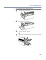
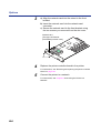
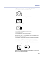
5
Place the media in the tray under the hooks.
The height of media should not exceed the limit mark on the tray, or
it may cause a jam.
NOTES:
• Load media with the print side down. Most media has instructions
recommending the side to be printed first.
• Do not mix different types or thicknesses of media in the media
tray at one time; this may cause a jam.
6
Connecting the
printer to a
computer
Slide the media tray completely into the slot.
Only one PC compatible computer can be directly connected to your printer.
35
Printer Setup
Using a parallel
interface cable
If you do not have a parallel interface cable, you will need to purchase one
from your local computer store or dealer. See “Bidirectional Parallel
Interface” on page 213.
To connect a parallel interface cable:
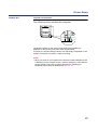
1
Make sure the computer, printer and the other
connected peripheral devices are turned off.
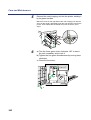
2
Connect the parallel interface cable to the computer’s
parallel interface connector and the printer’s parallel
interface connector.
Computer’s parallel
interface connector
NOTES:
• The actual connector on the computer may differ depending on
the manufacturer of the computer.
• If the cable is connected to the PC via a printer buffer or selector,
the printer may not print.
3
36
Connect the power cord to the printer’s AC inlet and to
an AC outlet.
Printer Setup
Power on
To power on the printer:
Turn ON the printer, and then the computer.
The Ready indicator on the printer starts flashing and Initializing is
displayed on the printer’s front panel. After approximately
5 minutes, the printer’s Ready indicator is lit and Ready is displayed on the
printer’s front panel. The printer is ready for printing.
NOTE:
• When you power on your system for the first time, if New Hardware Found
is displayed on the computer screen, close the dialog box, and install the
printing software using the procedure described in “Installing the
PostScript printer driver for Windows 95” on page 78.
37
Printer Setup
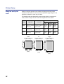
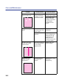
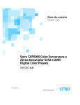
Margins and print
area
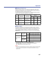
When the image is printed on the media, the image (print area) is a bit
smaller than the media size. You may need to adjust the page margins in the
application software to match the print area.
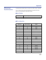
The following table and illustrations show the page sizes, the largest print
areas, and the margins for the media sizes supported on this printer.
Margins
Media
Page Size
Print area
Top
Sides
Letter
216 mm x 279 mm
(8.5" x 11")
208 mm x 270 mm
(8.2" x 10.6")
4.2 mm
(0.17")
4.3 mm
(0.17")
3.9 mm
(0.15")
A4
210 mm x 297 mm
(8.3" x 11.7")
201 mm x 289 mm
(7.9" x 11.4")
3.4 mm
(0.13")
3.9 mm
(0.15")
4.3 mm
(0.17")
Legal
216 mm x 356 mm
(8.5" x 14")
208 mm x 346 mm
(8.2" x 13.6")
3.2 mm
(0.13")
6.0 mm
(0.24")
3.9 mm
(0.15")
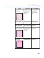
A4
210 mm x 297 mm
(8.3" x 11.7")
208 mm
(8.2")
Legal
216 mm x 356 mm
(8.5" x 14")
346 mm (13.6")
289 mm (11.4")
270 mm (10.6")
Letter
216 mm x 279 mm
(8.5" x 11")
38
Bottom
201 mm
(7.9")
208 mm
(8.2")
Printer Setup
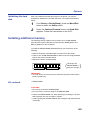
Loading media in
the multi-purpose
tray
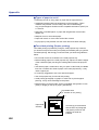
The multi-purpose tray (MPT) serves as an additional tray for loading any
type of media that ranges in size from 91 mm x 254 mm to 216 mm x 356
mm (3.6" x 10" to 8.5" x 14"). Use it to load a single sheet or a stack of
media, depending on the media’s type and thickness.
Use the multi-purpose tray to accomplish the following:
Print on standard and special media
• Standard media
— Laser paper [75 to 165 g/m2 (20 to 44 lbs.)]
• Special media
— Labels
— Envelope (#10 size) [Black Text only]
— Transparency (The print quality may not be stable. Use the media tray
for best reliability.)
Two-sided printing (double-sided) on laser paper
You should not expect the same print quality and reliability that you get with
one-sided printing. For details, see “Two-sided printing” on page 208.
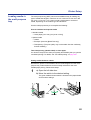
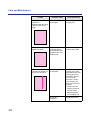
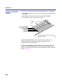
Setting media thickness switch:
Because the printer accommodates various media weights from the multipurpose tray, media thickness can be manually selected for the most
reliable paper-picking. Follow these steps:
1
a) Open the left side door.
b) Move the switch to the desired setting.
The green media thickness switch is located on the paper feeder
and has three settings:
b
a
Thin
Thick
Middle
39
Printer Setup
Switch setting
2
Media
Thin (Default)
Laser paper 75 to 90 g/m2 (20 to 24 lbs.)
Middle
Laser paper 91 to 123 g/m2 (25 to 32 lbs.)
Transparency, Label, Coated paper
Thick
Laser paper 124 to 165 g/m2 (33 to 44 lbs.)
Envelope
Close the left side door.
Loading Paper, Transparency:
NOTE:
• Reusing media that has been fed through the printer (for example, after
jams) can reduce the life of the consumables and paper path
components.
For detailed information on media, see “Media” on page 206.
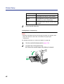
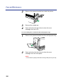
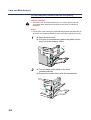
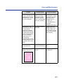
1
2
Set the media thickness switch (page 39).
a) Open the multi-purpose tray.
b) Extend the media support by sliding it outward.
a
b
40
Printer Setup
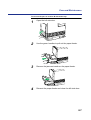
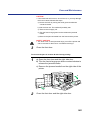
3
Separate the media guides to the approximate width of
the media.
4
Fan the media, and then tap it on a level surface to avoid
media jams or skewed printing.
NOTE:
• The recommended transparency is 3M CG3700. If the print
quality is poor, try printing on the other side.
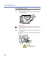
5
Insert the media with the printing side up into the multipurpose tray.
The height of media should not exceed the limit mark on the left
guide, or it may cause a media jam.
41
Printer Setup
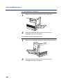
6
7
Adjust the media guides to the media size.
Use the printer driver to select the multi-purpose tray.
To load an envelope in the multi-purpose tray:
Do not insert more than one envelope at a time. Only black text can be
printed on envelopes. For more detailed information, see “Envelopes” on
page 210.
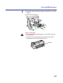
1
2
3
Set the media thickness switch (page 39).
Adjust the media guides to the width of the envelope.
Insert the envelope with the short end entering the
printer first and the printing side facing up.
The edge where the stamp will be located enters the printer last.
4
42
From your computer, use the printer driver to choose
Envelope from the Paper Size menu and Paper Source
menu.
Printer Setup
To load labels in the multi-purpose tray:
For detailed information on labels, see “Transparencies and labels” on
page 209.
1
2
3
Set the media thickness switch (page 39).
Adjust the media guides to the width of the label sheets.
Insert label sheets in the multi-purpose tray with the
printing side up and insert the top of the sheets first.
The height of labels should not exceed the limit mark on the guide.
4
Choose MPT Label as the paper source in the Paper
tab of the printer driver.
NOTE:
• Avoid printing labels if the temperature is too high; doing so may damage
consumables.
43
Printer Setup
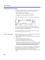
Using the front panel
The printer’s front panel enables you to set options and view the status of
the printer and print jobs. This section provides information about:
• Status messages and error messages
• Top-level menus you can access from the front panel
• Printing printer information pages from the front panel
This section describes the functions of the front panel, illustrated below:
READY
ERROR
MENU
/EXIT
ENTER
CANCEL
CONTINUE
The 2 line, 24 character LCD window on the front panel displays status
messages. When the printer is printing normally, status information about
the current jobs appear in the display window.
For a detailed explanation of the activity lights and buttons on the front
panel, see “Front panel overview” on page 27.
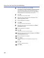
Status messages
When the printer is printing normally, status information about current jobs
appears in the display window. The messages are:
• Ready—Displays while the printer is ready to print but not processing or
printing a job.
•
•
•
•
Printing—Displays while a job is printing.
Processing—Displays while the job is processing.
Canceling Job—Appears when you cancel a print job.
Ready(Sleep)—Appears when the printer is in an power saver mode. This
mode can reduce the total power consumption of the printer to less than
35 watts. Full power mode is restored when the printer receives a job or
when you press the Menu/Exit button or print a page at the printer.
Before the printer can print after being in Ready(Sleep), it needs to warm up
to heat up the fuser. The actual warm-up time depends on how long the
printer has been in power saver mode. If the printer has been in
Ready(Sleep) power saver mode for a long time, the warm-up period will be
longer.
44
Printer Setup
Error messages
If there is a printing problem, the Error indicator will be on, and an error will
appear in the display window. For information about error messages, see
“Front panel status and error messages” on page 177.
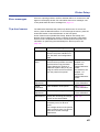
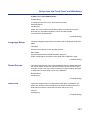
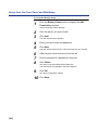
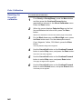
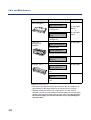
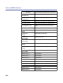
Top-level menus
The table below describes the printer’s top-level menus. To access the
menus, press the Menu/Exit button. To scroll through the menus, press the
Continue/Forward or Cancel/Left button on the front panel.
Some of these menus (Parallel Port Setup, Network Port Setup, and
Network Protocol Setup) are used to configure the printer’s initial Setup,
which must be completed before users can send jobs to the printer. For
information on performing the initial Setup from the front panel, see
page 106.
Choose
To specify
See also
Test Page
Printing one of three sample pages,
stored in the printer’s ROM: Font
List, Test Print, and Configuration
page.
Page 47
Check And
Print*
Printing additional copies of a
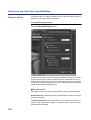
Check and Print job after the initial
Check and Print copy has been
printed. Specify the number of
additional copies of the job to print
using the Check and Print screens
from the printer’s front panel.
For Macintosh, see
Chapter 2 of
Drivers and
Utilities Reference
Guide.
For Windows, see
Chapter 1 of
Drivers and
Utilities Reference
Guide.
Bias
Adjustment
Toner density
See Chapter 7,
“Color Calibration”.
Visual
Calibration
Color calibration of the printer
See Chapter 7,
“Color Calibration”.
Color
Adjustment
Toner density and brightness
See Chapter 7,
“Color Calibration”.
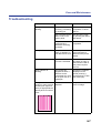
Maintenance
Display the remaining percentage
of each of the consumables.
Page 152
Image Area
The amount of the last printed page
covered by toner, for all toner
colors.
The average amount of the printed
page covered by toner, for all toner
colors since a toner cartridge
replacement.
Page 153
* This menu is available only on printers with a hard disk drive.
45
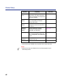
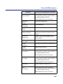
Printer Setup
Choose
To specify
See also
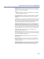
ENERGY
STAR
Enable entering ENERGY STAR
mode which can reduce the total
power consumption of the printer to
less than 35 watts.
Page 107
Parallel Port
Setup
Enable printing through the parallel
port, set parallel port timeout,
specify data mode.
Page 107
Network Port
Setup
Specify Ethernet or Token Ring
settings for network connections to
the printer.
Page 107
Network
Protocol
Setup
Specify settings for network
protocols, including TCP/IP,
AppleTalk, and IXP/SPX.
Page 109
Language
Specify the language of the LCD
text, and the language used in the
Test, Configuration, and Calibration
pages.
Page 111
Reset
Queues*
Clear all jobs from queues and
clear the Job Log.
Page 111
Hard Disk*
Initialize hard disk drive. .
Page 111
* These menus are available only on printers with a hard disk drive.
NOTE:
• Network Port Setup and Network Protocol Setup appear only for
networked printers.
46
Printer Setup
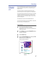
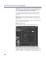
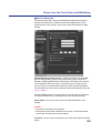
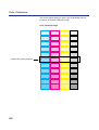
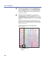
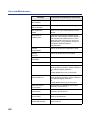
Printing pages
from the front
panel
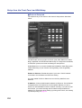
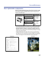
There are several pages that you can print from the front panel. This section
provides instructions for printing a Test Print, a Configuration Page, and
PostScript Font List.
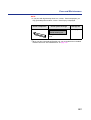
The Test Print includes a color sample as well as the printer’s name,
enabled network protocols, memory configurations, and installed options.
The Configuration Page lists information about the printer, the current Setup
configuration, and the number of printer fonts. It’s a good idea to print a
Configuration Page before you make Setup changes, in case you need to
restore some settings later.
The PostScript Font List print out the list of available printer fonts.
You can print a Test Print before you set up the KX-P8420—or at any other
time from the Ready or the Ready(Sleep) screen.
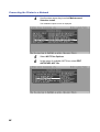
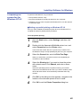
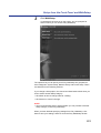
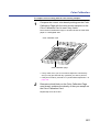
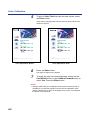
To print a Test Print:
1
Turn on the printer and allow it to warm up.
2
From the Ready screen, press the Menu/Exit button on
the printer’s front panel.
3
4
Press the Enter button.
Messages appear on the front panel as the KX-P8420 printer runs
through its power-up tests.
Press the Continue/Forward button until you see Test
Print and then press the Enter button.
Examine the quality of the Test Print.
Calibration: No
Panasonic KX-P8420
Configuration
Printer Name: KX-P8420
Resolution: 600 dpi x 600 dpi
Printer Language(s): PS3
Memory
Installed Memory (RAM): 32MB
Test Print
47
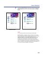
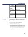
Printer Setup
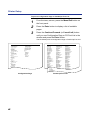
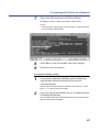
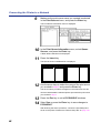
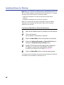
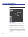
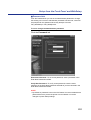
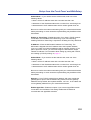
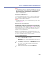
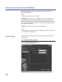
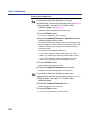
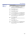
To print a Configuration Page or PostScript Font List:
1
From the Ready screen, press the Menu/Exit button on
the front panel.
2
Press the Enter button to display a list of available
pages.
3
Press the Continue/Forward (or Cancel/Left) button
until you see Configuration Page or PS Font List in the
window and press the Enter button.
The KX-P8420 prints a Configuration Page or PostScript Font List.
Configuration
Printer Name: KX-P8420
Number of Fonts: 251
Printer Information
Controller FW Date: XXXXXX
Controller Hardware Rev: X
PostScript Version: XXXX
Total Page Count: 4
CYAN: 099% remaining
MAGENTA: 099% remaining
YELLOW: 099% remaining
BLACK: 099% remaining
Imaging Unit: 099% remaining
Transfer Unit: 099% remaining
Fuser Unit: 099% remaining
Oil Roll: 099% remaining
Installed Options
Disk: Not Installed
Token Ring: Not Installed
Available Disk Space: 0MB
Installed Memory (RAM): 16MB
Image Area
Last
CYAN: 000%
MAGENTA: 000%
YELLOW: 000%
BLACK: 006%
Average
CYAN: 005%
MAGENTA: 008%
YELLOW: 001%
BLACK: 004%
System Setup
Printer Name: KX-P8420
Printed Queue: Disabled
ENERGY STAR (R): 30 min
Printer Setup
Page Description Language: PS
PostScript Setup
Error Page: No
Cover Page: No
VisualCal
Calibration: NO
Color Adjust
Brightness Adjustment: None
Color Adjustment: None
I/O Port
Ethernet: Disabled
Parallel Port: Enabled
I/O Timeout: 15
Data Mode: ASCII
Network Information
Ethernet MAC Address: 00:80:F0:11:00:2B
Ethernet TCP/IP: Disabled
AppleTalk: Disabled
Novell: Disabled
SMB: Disabled
Configuration Page
48
Page: 1
PostScript Font List
Printer Name: KX-P8420
Number of Fonts: 251
Page: 1
AlbertusMT
CooperBlack
Helvetica-Oblique
AlbertusMT-Italic
CooperBlack-Italic
HelveticaCE
AlbertusMT-Light
Copperplate-ThirtyThreeBC
HelveticaCE-Bold
AntiqueOlive-Bold
Copperplate-ThirtyTwoBC
HelveticaCE-BoldOblique
AntiqueOlive-Compact
Coronet-Regular
HelveticaCE-Cond
AntiqueOlive-Italic
CoronetCE-Regular
HelveticaCE-CondBold
PostScript
Font
List
Page: 2
Number of Fonts:
251
AntiqueOlive-Roman
Courier
HelveticaCE-CondBoldObl
Printer
Name:
KX-P8420
AntiqueOliveCE-Bold
Courier-Bold
HelveticaCE-CondObl
AntiqueOliveCE-Compact
Courier-BoldOblique
HelveticaCE-Narrow
NewYork
Univers-Oblique
AntiqueOliveCE-Italic
Courier-Oblique
HelveticaCE-NarrowBold
NewYorkCE
AntiqueOliveCE-Roman
CourierCE UniversCE-Bold
HelveticaCE-NarrowBoldOblique
Optima
UniversCE-BoldExt
Apple-Chancery
CourierCE-Bold
HelveticaCE-NarrowOblique
Optima-Bold
UniversCE-BoldExtObl
Apple-ChanceryCE
CourierCE-BoldOblique
HelveticaCE-Oblique
Optima-BoldItalic
UniversCE-BoldOblique
Arial-BoldItalicMT
CourierCE-Oblique
HoeflerText-Black
Optima-Italic
UniversCE-Condensed
Arial-BoldMT
Eurostile
HoeflerText-BlackItalic
OptimaCE-Bold
UniversCE-CondensedBold
Arial-ItalicMT
Eurostile-Bold
HoeflerText-Italic
OptimaCE-BoldItalic
UniversCE-CondensedBoldOblique
ArialCE
Eurostile-BoldExtendedTwo
HoeflerText-Ornaments
OptimaCE-Italic
UniversCE-CondensedOblique
ArialCE-Bold
Eurostile-ExtendedTwo
HoeflerText-Regular
OptimaCE-Roman
UniversCE-Extended
ArialCE-BoldItalic
EurostileCE
HoeflerTextCE-Black
Oxford
UniversCE-ExtendedObl
ArialCE-Italic
EurostileCE-Bold
HoeflerTextCE-BlackItalic
Palatino-Bold
UniversCE-Light
ArialMT
EurostileCE-BoldExtendedTwo
HoeflerTextCE-Italic
Palatino-BoldItalic
UniversCE-LightOblique
AvantGarde-Book
EurostileCE-ExtendedTwo
HoeflerTextCE-Regular
Palatino-Italic
UniversCE-Medium
AvantGarde-BookOblique
Geneva
JoannaMT
Palatino-Roman
UniversCE-Oblique
AvantGarde-Demi
GenevaCE
JoannaMT-Bold
PalatinoCE-Bold
Wingdings-Regular
AvantGarde-DemiOblique
GillSans
JoannaMT-BoldItalic
PalatinoCE-BoldItalic
ZapfChancery-MediumItalic
AvantGardeCE-Book
GillSans-Bold
JoannaMT-Italic
PalatinoCE-Italic
ZapfChanceryCE-MediumItalic
AvantGardeCE-BookOblique
GillSans-BoldCondensed
JoannaMTCE
PalatinoCE-Roman
ZapfDingbats
AvantGardeCE-Demi
GillSans-BoldItalic
JoannaMTCE-Bold
StempelGaramond-Bold
AvantGardeCE-DemiOblique
GillSans-Condensed
JoannaMTCE-BoldItalic
StempelGaramond-BoldItalic
Bodoni
GillSans-ExtraBold
JoannaMTCE-Italic
StempelGaramond-Italic
Bodoni-Bold
GillSans-Italic
LetterGothic
StempelGaramond-Roman
Bodoni-BoldItalic
GillSans-Light
LetterGothic-Bold
StempelGaramondCE-Bold
Bodoni-Italic
GillSans-LightItalic
LetterGothic-BoldSlanted
StempelGaramondCE-BoldItalic
Bodoni-Poster
GillSansCE-Bold
LetterGothic-Slanted
StempelGaramondCE-Italic
Bodoni-PosterCompressed
GillSansCE-BoldCondensed
LetterGothicCE
StempelGaramondCE-Roman
BodoniCE
GillSansCE-BoldItalic
LetterGothicCE-Bold
Symbol
BodoniCE-Bold
GillSansCE-Condensed
LetterGothicCE-BoldSlanted
Tekton
BodoniCE-BoldItalic
GillSansCE-ExtraBold
LetterGothicCE-Slanted
Times-Bold
BodoniCE-Italic
GillSansCE-Italic
LubalinGraph-Book
Times-BoldItalic
BodoniCE-Poster
GillSansCE-Light
LubalinGraph-BookOblique
Times-Italic
BodoniCE-PosterCompressed
GillSansCE-LightItalic
LubalinGraph-Demi
Times-Roman
Bookman-Demi
GillSansCE-Roman
LubalinGraph-DemiOblique
TimesCE-Bold
Bookman-DemiItalic
Goudy
LubalinGraphCE-Book
TimesCE-BoldItalic
Bookman-Light
Goudy-Bold
LubalinGraphCE-BookOblique
TimesCE-Italic
Bookman-LightItalic
Goudy-BoldItalic
LubalinGraphCE-Demi
TimesCE-Roman
BookmanCE-Demi
Goudy-ExtraBold
LubalinGraphCE-DemiOblique
TimesNewRomanCE
BookmanCE-DemiItalic
Goudy-Italic
Marigold
TimesNewRomanCE-Bold
TimesNewRomanCE-BoldItalic
TimesNewRomanCE-Italic
TimesNewRomanPS-BoldItalicMT
TimesNewRomanPS-BoldMT
TimesNewRomanPS-ItalicMT
Ti
N R
PSMT
PostScript Font List
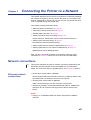
Chapter 3
Connecting the Printer to a Network
This chapter describes how to connect your printer to a network by installing
the network card (option). You can connect the printer to your network with
thicknet, twisted pair, or thinnet. You can also connect your printer directly to
a PC compatible through the parallel port.
This chapter provides information about:
•
•
•
•
“Ethernet network connections” on page 49
“Token Ring network connections” on page 51
“Parallel cable connection” on page 52
“Setting up TCP/IP clients for printing” on page 59
TCP/IP stands for Transmission Control Protocol/Internet Protocol.
• “Setting up IPX (Novell) printing” on page 61
IPX stands for Internet Packet Exchange.
• “Setting up Windows 95 clients for SMB printing” on page 73
• “Setting up Windows NT 4.0 clients for SMB printing” on page 76
SMB stands for Server Message Block.
After you have connected the printer to the network, follow the setup
instructions in “Chapter 6 Setup from the Front Panel and WebSetup”.
Network connections
This section describes the types of network connections supported by the
KX-P8420. Optional network cards are available from your Panasonic
dealer. For more information on upgrade options, see “Chapter 9 Options”.
Ethernet network
connections
• Thinnet (thin coaxial cable or 10Base2)
Uses an external transceiver (media access unit, or MAU) to attach to the
AUI (attachment unit interface) connector on the printer.
• Thicknet (thick coaxial cable or 10Base5)
Cable connects directly to the AUI connector on the printer.
• Twisted pair (Category 5 unshielded twisted pair cable or 100BaseTX)
Uses 8-pin RJ-45 connector that plugs into the RJ-45 socket on the
printer.
NOTE:
• Category 3, unshielded twisted pair cable is supported on 10BaseT
networks.
49
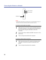
Connecting the Printer to a Network
AUI connector
RJ-45 socket
Parallel port
NOTE:
• Shut off the printer before connecting it to any network device. Only one
Ethernet connection should be made to the printer at a time.
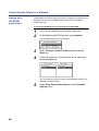
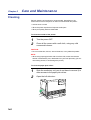
To connect a thinnet cable to the printer:
1
With the printer turned off, connect the MAU transceiver
to the AUI connector on the back of the printer. Secure
the connection using the slide latch on the AUI
connector.
2
Connect the thinnet cable to the BNC connector on the
transceiver.
3
Turn on the printer and then the computer.
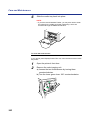
To connect a thicknet cable to the printer:
50
1
With the printer turned off, connect the thicknet cable
connector to the AUI connector on the back of the
printer.
2
Turn on the printer and then the computer.
Connecting the Printer to a Network
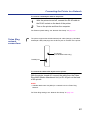
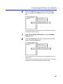
To connect a twisted pair cable to the printer:
1
With the printer turned off, connect the RJ-45 cable to
the RJ-45 socket on the back of the printer.
2
Turn on the printer and then the computer.
For Ethernet speed setting, see “Network Port Setup” on page 107.
Token Ring
network
connections
The printer supports the shielded twisted pair cable (Category 5 shielded
twisted pair cable) that plugs into the RJ-45 jack on the back of the printer.
RJ-45 jack
(Use shielded cable only.)
Parallel port
To connect the cable to RJ-45 jack on the printer:
With the printer turned off, connect the cable from the Token
Ring MAU (Media Attachment Unit) to RJ-45 jack on the back
of the printer.
NOTE:
• A Media Attachment Unit (MAU) is a network hub for a Token Ring
Network.
For Token Ring settings, see “Network Port Setup” on page 107.
51
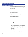
Connecting the Printer to a Network
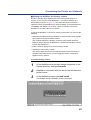
Parallel cable connection
In addition to receiving print jobs over the network, the printer can accept
print jobs directly from an IBM compatible computer through its high-speed,
Centronics compatible parallel port. This connection is also advantageous
for workstations on dedicated networks using protocols other than
AppleTalk, TCP/IP, or IPX.
The parallel port connection can be used simultaneously with a network
connection.
CAUTION:
• Always use a shielded interface cable. Use of an unshielded cable can
result in radio interference with data.
NOTE:
• Printing through a serial port (Local Talk) is not supported on Macintosh
computers.
To connect a parallel cable to the printer:
Parallel port
1
With the printer and the computer turned off, attach the
Centronics Type C parallel cable (not included) to the
parallel port.
2
Connect the other end of the cable to the parallel port on
the computer.
3
Turn on the printer and turn on the computer.
For parallel port settings, see “Parallel Port Setup” on page 107.
52
Connecting the Printer to a Network
Setting up TCP/IP printing
TCP/IP provides network services for high-speed local and wide area
networks and heterogeneous environments including PC compatibles,
Macintosh computers, minicomputers, and mainframes running diverse
operating systems. The printer supports the lpr protocol for printing over
TCP/IP networks. Network users submit print jobs to a named printer.
Workstations on a TCP/IP network can print directly to the printer, or can
print to a Windows NT 4.0 server or UNIX workstation acting as a print
server.
Before you install the printer on a TCP/IP network, you need to obtain a
unique IP address. Contact your network administrator for this information.
Setting up the
printing
environment
To set up printing on a TCP/IP network, the network administrator must
follow these steps:
To set up IP Address/Subnet mask on the KX-P8420:
1
From the Ready screen, press the Menu/Exit button on
the front panel to access the printer setup menus.
2
Press the Continue/Forward button until you see
Network Protocol Setup on the LCD. Press the Enter
button to access the TCP/IP Setup menus.
In the next step you will enable TCP/IP network communication
according to your network type.
3
Press Enter to advance to the Enable TCP/IP? screen.
Press Enter and press Continue/Forward to select
Yes, and then press Enter again to advance to the
Ethernet IP Address screen. Press Enter.
4
Use the Continue/Forward button to select a number in
a valid, unique IP Address for the KX-P8420. Press
Cancel/Left button to accept a number and move to the
left—to the next number.
NOTE:
• On the KX-P8420 printer, numbers are entered from right to left.
Press the Continue/Forward button to scroll through numbers
from 0 to 9. Press the Cancel/Left button to accept a number and
move to the next.
53
Connecting the Printer to a Network
5
When you have finished entering all numbers in the
address, press Enter to advance to the Subnet Mask
screen.
6
Use the Continue/Forward button to select a number
as the Subnet Mask value for the KX-P8420. Press
Cancel/Left button to accept a number and move to the
left—to the next number.
7
Specify the Gateway Address in the printer’s Setup
menus, if needed.
See “Network Protocol Setup” on page 109 for details.
8
When you have finished entering all numbers, press
Menu/Exit button.
After being rebooted, the printer will return to Ready mode.
■ Setting up NIS server
If the site is using NIS (Network Information Services), a superuser must
add the printer name and IP address to the system’s database of network
printers.
1
Add the KX-P8420 to the network’s IP host table.
2
For the printer name, specify the print server protocol,
the print connection (queue), and the spool file.
3
Activate the printer connection.
This step must be performed on the master NIS (server) machine.
After adding the printer entry, the updated database must be
released to network users.
Depending on your system, you may restart the printer daemon or
tell the printer to accept print requests.
■ Print Queues
Print spooling is the process of sending a print jobs to a defined location on
a hard disk, in this case the Print or Hold queues. Printers without a hard
disk drive can only receive print jobs over the Direct connection. Jobs sent
to the Direct connection are transferred from the computer to the printer’s
SDRAM.
32
54
NOTE:
• If the printer has a hard disk drive and 32 MB of memory installed, Direct,
Print, and Hold print connections are automatically available. If the printer
does not have a hard disk drive, only the Direct connection is available.
Connecting the Printer to a Network
UNIX server
print queues
The lpr protocol is a printer spooling system. It is a set of programs that
accepts printing requests from many users on a network, routes them to the
proper print server (in this case, the KX-P8420), and accepts requests to
display a queue’s status or to remove jobs from a queue.
The lpr system is included in the standard installation of Berkeley-based
UNIX systems, SunOS 4, and Solaris.
Use the examples that follow as a guide in helping you set up your network
for printing to the printer.
NOTE:
• In these examples, KX-P8420 is used as the printer name (the IP host
name), and KX-P8420q is used to indicate the KX-P8420 Print queue.
Since the printer supports only one TCP/IP (lpr) connection at a time, you
can use the same name for the hostname and the queuename. However,
the examples indicate where you should make a distinction if you want to
use different names.
To add the printer as a network printer to all UNIX systems:
1
2
Log in to your UNIX host as the root user.
Edit your /etc/hosts file to include the printer as a
network device.
The following is a sample entry for the printer:
192.9.228.1<TAB>KX-P8420<TAB>#comments
where <TAB> indicates that you press the tab key.
The IP address is followed by the official host name, and these are
followed by aliases, if any. Type the entry exactly as shown, without
a space before the IP address.
NOTE:
• For sites that use DNS (Domain Name System) or that use NIS or
NIS+, consult the documentation or the network administrator for
instructions on publishing the printer entry.
3
4
Save and exit the hosts file.
Confirm the connection using the ping command.
See “Verifying the TCP/IP network connection” on page 58.
55
Connecting the Printer to a Network
5
If your UNIX system uses SunOS 4 or another BSDbased variant, go to the next section.
If your system uses Solaris 2, follow the steps on page 57.
To set up printing on a UNIX system running SunOS 4 or another
BSD based variant:
1
On each workstation that will print to the printer, log in to
your UNIX host as the root user.
2
Create an entry for the printer in your /etc/printcap file.
The following is a sample printcap entry for the printer. Note that the
remote host name you enter in the rm line must exactly match the
name you entered in the /etc/hosts file.
KX-P8420q:\
:lp=:\
:rm=KX-P8420:\
:rp=xjprint:\
:lf=/var/spool/lpd/KX-P8420q/log:\
:sd=/var/spool/lpd/KX-P8420q:\
:mx#0:sf:sb
The spool directory KX-P8420q is specified here, and the directory
itself is created in step 3. Similarly, the log file is specified here and
created in step 4. The spool directory is write-protected (from
everyone but a daemon user and daemon group); users cannot
modify or remove files other than their own.
It is possible to set up to two additional printer entries, one with the
rp name xjprint and one with the name xjhold. The rp name
indicates the KX-P8420 queue to which jobs are sent when you
print to the named printer.
A printer entry with the rp name xjhold routes all jobs to the
KX-P8420 Hold queue. Therefore, to print those jobs, they must be
moved to the Print queue or deleted using Fiery WebSpooler.
NOTE:
• Printers without a hard disk drive and 32 MB of memory can not
use Print or Hold queues (rp name: xjprint and xjhold), they can
only receive print jobs over the Direct connection. Use the rp
name xjdirect if your KX-P8420 has no hard disk, or is configured
with less than 32 MB of memory.
56
Connecting the Printer to a Network
3
Create a spool directory for the printer in the /var/spool
directory.
For example, enter the following:
mkdir -p /var/spool/lpd/KX-P8420q
chown daemon /var/spool/lpd/KX-P8420q
4
Create the log files.
For example, enter the following:
cp /dev/null /var/spool/lpd/KX-P8420q/log
5
Reboot the machine.
To set up printing on a UNIX system running Solaris 2:
1
On each workstation that will print to the printer, log into
the UNIX system as the root user.
2
At the UNIX prompt, type lpsystem -t bsd KX-P8420
3
Type lpadmin -p KX-P8420q -s KX-P8420\!xjdirect
This tells your system that the printer is a print server of bsd
(Berkeley Software Distribution) type.
This command creates an internal queue on the workstation and
points it to the printer. The general format of this command is:
lpadmin -p <queuename> -s <hostname>\!xjdirect
NOTE:
• The name xjdirect after the exclamation point is for configuring
the printer; it is an internal name that the printer requests. It must
be xjdirect; it is not a user-selectable name. This is the only place
where it is entered.
As with SunOS 4 or other BSD based systems, when printing to
printers with a hard disk and a minimum of 32 MB of memory it is
possible to configure up to two additional printer entries, one with
the rp name xjprint and one with the rp name xjhold (see page 56).
4
Type accept KX-P8420q
5
Type enable KX-P8420q
This command tells the printer to accept print requests from your
workstation. You are now ready to print from the workstation to the
printer.
57
Connecting the Printer to a Network
Verifying the
TCP/IP network
connection
Before a device on a TCP/IP network can send print jobs to the printer, the
printer must be given a valid IP address and subnet mask, as well as a
gateway address, if applicable. The printer is given these addresses in the
printer’s Network Protocol Setup. The IP address is used on all TCP/IP
networks and must always be assigned before the printer can be verified
across the network.
Because TCP/IP networks require some UNIX setup by the network
administrator, you may not be able to send a test page from the driver
across the network to the printer immediately after installation. The following
procedure enables you to verify that there is a proper connection between
the printer and the network without using the printer driver to print a test
page. Before you begin this procedure, verify that the printer is functioning
by printing a page from the printer’s ROM.
For step by step instructions, see “Printing pages from the front panel” on
page 47.
Once the printer’s TCP/IP setup is complete, you can verify the availability
of the printer using the ping command from the DOS prompt with Windows
95, from the Command prompt with Windows NT 4.0 or from UNIX.
To verify the TCP/IP connection:
To see if the printer responds to its address, use the ping
command.
Use the format:
ping <IP address>
Use the printer IP address assigned in Network Protocol Setup. After the
printer has been given a hostname by your network administrator, you can
also ping the name you gave it:
ping <hostname>
The server should respond with a message such as:
<IP address> is alive.
Some systems will respond with a continuous display of output from the IP
address. To stop the output, type Control-C
58
Connecting the Printer to a Network
Setting up TCP/
IP clients for
printing
If the printer is being added to an existing network, each TCP/IP client is
already running TCP/IP client software.
The KX-P8420 supports TCP/IP client software on UNIX workstations, PC
compatibles, and Macintosh computers. With Macintosh computers
however, it is easiest to use the built-in AppleTalk protocol to communicate
directly with the printer.
If the client workstation is a PC running Windows, set up the printer as a
Windows PostScript printer by installing the PostScript printer driver, as
described in Chapter 4. For setting up your networking software, see the
documentation for your networking environment.
Setting up TCP/
IP clients for
running
Fiery WebTools
Fiery WebTools software comes pre-installed on the KX-P8420.
Fiery WebTools include: WebSpooler, Status, WebDownloader, WebSetup
and WebLink.
When TCP/IP is enabled for the printer in Network Protocol Setup,
Fiery WebTools are immediately available to clients that:
• Are connected to a TCP/IP network with a consistent set of IP addresses,
one for the printer and one for each computer connect to the printer.
• Have an Internet connection and a Java enabled Web browser.
The recommended browsers are:
• Netscape Navigator 3.04 for Macintosh computers,
• Microsoft Internet Explorer 4.0.1 SP1 or Netscape Communicator 4.0.4
for Windows computers.
NOTE:
• Microsoft Internet Explorer 3.x does not support the WebDownloader.
Netscape and Microsoft continue to release frequent updates to their
browsers. As support cannot be guaranteed for all versions, use the
versions specified above for best results.
To access Fiery WebTools, enter the IP address or DNS name of the
KX-P8420 as a URL in the Internet browser. For more information, see
page 70.
59
Connecting the Printer to a Network
Printing and
administering
print jobs
Once the printer has been properly installed on the TCP/IP network, users
should be able to send print jobs to the KX-P8420 from most applications.
UNIX clients also commonly use UNIX printing commands to print
PostScript files and text files to the printer.
For information on printing PostScript files and text files using UNIX
commands, see Chapter 3 of Drivers and Utilities Reference Guide.
If you have superuser privileges you can remove any lpd jobs from the
printer queue; removing your own jobs doesn’t require special privileges.
To remove jobs from the printer queue:
On a UNIX system running SunOS 4 or other BSD-based
variant, use the lprm command to remove jobs from the queue.
To remove job number 123 from the print queue of your KX-P8420 named
printer, you would type:
lprm -P<printername> <job #…>
or, for example: lprm -PKX-P8420 123
The lprm command reports the names of any files it removes.
To determine the job number, use the lpq command described below.
lpq -p<printername>
On a UNIX system running Solaris 2, use the cancel command
to remove jobs from the queue.
Type:
cancel <job ID>
For example, to remove a job whose ID is printer-123 from the print queue
of your KX-P8420, type:
cancel printer-123
To find out a print job’s job ID, use the lpstat command described below:
On a UNIX system running Solaris 2, use the lpstat command
to see printer jobs in the queue.
lpstat -o <queuename>
For example, if your printer queue is named KX-P8420q, type:
lpstat -o KX-P8420q
The returned list of jobs includes each job ID.
Once lpr print jobs are spooled to the printer’s hard disk, you can use
WebSpooler to monitor print jobs.
60
Connecting the Printer to a Network
Setting up IPX (Novell) printing
IPX, Novell’s Internetwork Packet Exchange protocol, runs on networks that
include a Novell NetWare server. The server, typically a dedicated PC, is
usually configured to control workstation access to shared resources. In
addition to other services, NetWare servers use IPX protocols to provide
spooling, queue management, and print services to computers (including
Macintosh, DOS, UNIX, and VAX) whose operating software is compatible
with IPX protocols.
This section describes network setup for an IPX (Novell) network.
Overview of IPX
printing to the
KX-P8420
NetWare file servers support the creation of print queues, storage areas for
print jobs. When a user on a network workstation prints a job, the job is sent
to a print queue on the NetWare server. The job is spooled to the NetWare
file server disk, freeing up the workstation.
The queues on the NetWare server must be named to match the Direct
connection and Print queue on the KX-P8420. The NetWare queue names
should be given an extension corresponding to the KX-P8420 printing
connection, as follows:
_print
_hold
_direct
NOTE:
• The NetWare queues names must be given the above all lowercase
English extension (_print, _hold or _direct), even if any language’s
NetWare server is used.
When the KX-P8420 is configured to connect to a NetWare server, it polls
the NetWare server for jobs in each of its queues. If jobs are found, they are
transferred over the network to the matching connection: Print to Print,
Direct to Direct. While a job is processed and printed, a record of the job is
being created. You can access the Job Log containing these records at any
time.
When the printer is connected to a NetWare print queue that is defined on
the NetWare server, the printer polls the queue for jobs and receives them
over the network for immediate processing and printing. All printer jobs are
sent from the printer queue on the NetWare server to the KX-P8420.
NOTE:
• It is not recommended to connect KX-P8420 directly to NetWare server
via LPT port. It may cause unexpected print result.
61
Connecting the Printer to a Network
To set up network printing, enable IPX/SPX Setup from the printer’s front
panel (see “Network Protocol Setup” on page 109), and set up the PServer
using WebSetup after configuring the NetWare server (see “PServer Setup
tab” on page 120).
Configuring the
NetWare server
This section explains how to set up the NetWare server so that networked
users can print to the printer from their workstations. There are two stages
to this setup:
• The network administrator must set up a print queue on the NetWare
server so users can print to it, and the printer can receive print jobs
from it.
• Optionally, the administrator can set up the server for network installation
of PostScript printer drivers on client workstations.
Before configuring a NetWare file server for printing to the KX-P8420, make
sure that it is connected to a functioning IPX network. Then, log in as the
supervisor on a PC connected to the NetWare file server, and configure the
file server as described in the following sections.
Before you begin, you’ll need to determine the following names:
• The name of the NetWare file server on which you will define the printer
as a new print server.
• The name of the NetWare print server. This name is used for
communication between the printer and the NetWare file server.
• The name to assign to the KX-P8420 Direct, Print or Hold queue. If you
are defining a Hold queue, the last five characters must be _hold. You
need to set up at least one print queue on the NetWare server for jobs
that will be printed by the printer. Users will see and print to the name you
assign to the Print queue.
Names should be as brief and descriptive as possible. Server names
cannot begin with a period and cannot include spaces or punctuation
characters other than periods.
• To complete network setup, you will need to log in to the NetWare file
server and the new print server from the printer. You will need a login
name and, if access to the server is restricted, a login password.
62
Connecting the Printer to a Network
■ Setting the NetWare 4.x bindery context
Novell 4.x servers use a different environment setup than Novell 3.1x
servers. (If your server is using NetWare 3.x, proceed to “Setting up a
KX-P8420 print queue” on page 66.) The native structure for Novell 4.x
objects is known as Novell Directory Services (NDS). To provide backward
compatibility with Novell 3.1x services, Novell 4.x servers use Bindery
Emulation to “act” like a Novell 3.1x server.
To set up the NetWare 4.x server for printing to the printer, you must do the
following:
• Determine the NDS path to the container in which the print server and the
print queue for the printer will be created.
The container defines the bindery context for your network structure.
Network devices that are not NetWare 4.x-aware need a bindery context
to work with NetWare 4.x.
• Edit the network startup file to set the bindery context.
• Activate the new bindery context.
This section describes the second and third steps. Given the variety of
possible network structures, we can’t suggest a bindery context that
applies to every network.
To set the bindery context:
1
At the NetWare drive prompt, change directories to the
System directory, and type rconsole
2
Establish a connection with the server that will have the
printer queue.
3
At the NetWare prompt type load install
The NetWare Server Installation window is displayed.
63
Connecting the Printer to a Network
4
Use the down arrow key to select Maintenance/
Selective Install.
The Installation Options menu is displayed.
5
6
64
Select NCF Files Options.
In the menu of available NCF files, select EDIT
AUTOEXEC.NCF file.
Connecting the Printer to a Network
7
Type a new line anywhere in the file as follows:
set Bindery Context = (Enter your bindery context here)
NOTE:
• To the right of the equals sign, type the bindery context obtained
from the system administrator.
8
9
Press Esc to close the window, and save changes.
Proceed to the next section.
To activate the bindery context:
1
If you cannot reboot the NetWare server at this point,
type the set command manually at the server’s
command prompt.
Use the same command that you entered in the autoexec.ncf file
(see step 7 in the previous procedure).
2
If you can reboot the NetWare server, the set command
is loaded automatically.
You are ready to set up the KX-P8420 print server and print queue.
See the next section for details.
65
Connecting the Printer to a Network
Setting up a
KX-P8420
print queue
The NetWare print server and print queue are created and configured from
NetWare Print Console, a NetWare utility that is stored in NetWare’s
PUBLIC directory.
To set up the NetWare server for printing to the KX-P8420:
1
2
Log in to the NetWare server as the Supervisor.
3
Select Change Current File Server and press the
Enter key.
4
Using the arrow keys, select the file server name and
press the Enter key.
At the NetWare MS-DOS prompt, type pconsole
The Available Options menu is displayed.
You must select this file server later as the NetWare File Server in
WebSetup>Network Setup.
5
66
Select Print Server Information from the Available
Options menu.
Connecting the Printer to a Network
6
Press the Insert key, type a name for the new print
server, and press the Enter key. Then press the Esc
key.
You must select this print server later as the NetWare Print Server
in WebSetup>Network Setup.
7
Select Print Queue Information from the Available
Options menu.
8
Press the Insert key and type a name for a new print
queue. Press the Enter key.
The print queue name you entered will be highlighted in the Print
Queues list.
If the print server manages more than one print queue, you’ll have
to select this name later in WebSetup>Network Setup.
67
Connecting the Printer to a Network
9
Make sure the print queue name you created is selected
in the Print Queues menu, and press the Enter key.
The Print Queue Information menu is displayed.
10
In the Print Queue Information menu, select Queue
Servers, and press the Enter key.
A blank Queue Servers list is displayed.
11
Press the Insert key.
The Queue Server Candidates list is displayed.
Queue Server Candidates
Color_Printer
PARALLEL
12
Queue Servers
(Print Server)
(Print Server)
Use the arrow keys to select the name of the print server
you created in step 6 and press the Enter key.
The server name you select will appear in the Queue Servers list.
You have associated the selected printer queue with the print server
you created in step 6.
13
14
Press the Esc key to exit all PCONSOLE windows.
Select Yes or press the Enter key to save changes to
PCONSOLE.
After finishing the above procedure, connect the specified queue
server to the printer. Please see “PServer Setup tab” on page 120.
68
Connecting the Printer to a Network
Setting up
NetWare Windows
clients
Before setting up client workstations, make sure you perform Network
Setup on the printer, and that the settings reflect the entities you created in
PCONSOLE.
Client setup has two parts:
• Install the PS printer driver on each Windows workstation.
• Configure the printer driver to print to a print queue on a Novell file server.
For instructions on installing the appropriate printer driver for your system
see “Chapter 4 Installing Software for Windows”.
For instructions on configuring the printer driver to print to a Novell file
server print queue, see page 80 for Windows 95, or page 92 for
Windows 3.1.
Using AppleTalk with Macintosh computers on an IPX
(Novell) network
Macintosh users on an IPX network can print to the printer in two ways:
• Directly, using AppleTalk and bypassing the NetWare server
• Through a NetWare server running NetWare for Macintosh
Since the printer supports both AppleTalk and IPX protocols at the same
time, it’s not necessary to use the second option. However, a network
administrator may choose to route all print jobs through a server.
NOTES:
• The printer can be attached to only one NetWare server at a time.
• Printing via the AppleTalk port of Windows NT 4.0 is not recommended as
it may cause additional, unnecessary pages to be printed.
■ Printing directly to the printer
Due to the layered design of networks, data can be transmitted using more
than one network protocol. When Macintosh computers are connected to an
IPX network, they can continue to transmit data over Ethernet cable using
AppleTalk protocols. If the printer is on the same network, Macintosh
computers can see and print to the printer, provided that AppleTalk is
enabled on the Macintosh and in Network Protocol Setup.
69
Connecting the Printer to a Network
Setting up Fiery WebTools
Fiery WebTools allow you to manage your KX-P8420 remotely from the
Internet or from your company’s intranet. The KX-P8420 has its own home
page, from which you are able to select from a variety of functions including
Status, Fiery WebSpooler, WebLink, Fiery WebDownloader, and
Fiery WebSetup.
IMPORTANT:
• Before you can send jobs to the printer, you must use Fiery WebSetup to
complete the process of configuring Setup options, as described starting
on page 112. Therefore, you must complete the procedures described in
this section and in “Completing setup from Fiery WebSetup” on page 112
before you can send jobs to the printer.
For information on using Fiery WebTools (other than Fiery WebSetup), see
Drivers and Utilities Reference Guide.
In order for network users to access and use Fiery WebTools, you need to
set network communication options in Network Protocol Setup on the front
panel. See “Setting up the printing environment” on page 53. You also need
to prepare each user’s workstation to communicate with the KX-P8420
using Fiery WebTools over the Internet or intranet. Once the initial Setup
has been performed from the printer’s front panel, you must complete the
Setup configuration from Fiery WebSetup.
In order for client workstations to access Fiery WebTools, they must use a
Web browser. The recommended browser versions are:
• Netscape Navigator 3.04 for Macintosh computers,
• Microsoft Internet Explorer 4.0.1 SP1 or Netscape Communicator 4.0.4
for Windows computers.
NOTES:
• Microsoft Internet Explorer 3.x does not support the Fiery
WebDownloader.
• Netscape and Microsoft continue to release frequent updates to their
browsers. As support cannot be guaranteed for all versions, use the
versions specified above for best results.
• Accessing to WebSetup via Netscape Navigator 3.04 for Macintosh
Computers is slow and not recommended.
• It is not recommended to open WebTools at several locations
simultaneously because it might adversely affect network printing.
• WebDownloader is not supported for Macintosh Computers.
70
Connecting the Printer to a Network
• If Java Applet is not set to Enable, you can not access the Fiery
WebTools. Follow the next steps:
Netscape 4.x
1. Select Preferences in the Edit menu.
The Preferences window appears.
2. Select Advanced in the Category.
3. Click the boxes next to Enable Java and Enable JavaScript.
4. Click OK.
Netscape 3.x
1. Select Network Preferences in the Options menu.
The Preferences window appears.
2. Click the Languages tab.
3. Click the boxes next to Enable Java, and Enable JavaScript.
4. Click OK.
Internet Explorer 4.x
1. Select Internet Options in the View menu.
2. Click the Security tab.
3. Click the circle next to Custom (for expert users) in the Local Intranet
zone.
4. Click Settings button.
The Security Settings window appears.
5. Click Custom in Java permissions, and click Java Custom Settings
button.
The Local intranet zone window appears.
6. Click the Edit Permissions tab, and click Enable in Run Unsigned
Content.
7. Click OK three times.
71
Connecting the Printer to a Network
Instructions below apply to computers using Ethernet protocols.
To use Fiery WebTools on each client workstation:
1
2
Enable TCP/IP on the KX-P8420.
3
Make sure the workstation is installed with an Internet
browser.
4
5
Launch the Internet browser.
Make sure the workstation has a valid, unique
IP address.
Enter the IP address or DNS name of the printer in the
browser’s URL line.
The printer’s home page appears. For more information on using
Fiery WebTools, see page 112 and “Chapter 4 Managing Print
Jobs” in Drivers and Utilities Reference Guide.
72
Connecting the Printer to a Network
Setting up Windows 95 clients for SMB printing
The following instructions describe printing to a network port using the
Details tab of the Printer Properties dialog. You must specify the option
settings including Server Name in the Service Setup screen, before SMB
printing is enabled. See “Service Setup tab” on page 125.
NOTE:
• The Details tab of the Printer Properties dialog is not available when the
dialog is accessed using File>Print from within applications. This tab
appears only when the Printer Properties dialog is accessed via the
Printers folder.
To set up SMB printing on Windows 95:
1
From the Start menu, choose Settings, and click
Printers.
2
Select the Panasonic KX-P8420 printer icon, and choose
Properties from the File menu.
3
Click the Details tab in the Properties window and click
Add Port.
4
In the Add Port dialog box, click Network, and click
Browse to display your network environment.
73
Connecting the Printer to a Network
5
32
Expand the levels to locate your printer and the queue
you want to print to.
If your printer has a hard disk drive and 32 MB of memory, three
connections will automatically be created when the KX-P8420
printer driver is installed. These connections are represented on the
network by the Direct, Print and Hold printer icons. If your printer
does not have a hard disk drive and 32 MB of memory, only the
Direct printer icon will be available.
If the Hold queue is specified, all jobs sent to the printer will be held
on the printer’s hard disk and will be visible in the WebSpooler
window until they are printed or deleted.
The printer you are browsing for is the SMB Name Server. If you do
not know the name of the SMB Name Server and SMB printing has
been enabled on the printer, refer to the printer’s Configuration
page for this information.
For instructions on printing a Configuration page, see “Printing
pages from the front panel” on page 47.
NOTE:
• If the local network does not include a WINS server, your printer
may not be visible in the Browse dialog box. In this case, you
must type the correct path for the print connection in the “Specify
the network path to the printer” box of the Add Port dialog box, for
example: \\KX-P8420\direct.
6
74
Under the printer’s name, select the queue you wish to
print to and click OK.
Connecting the Printer to a Network
7
In the Add Port dialog box, verify that the network path
is correct and click OK.
8
To confirm the connection, click the General tab in the
Properties dialog box.
9
Click Print Test Page and click OK.
If the test page prints successfully, you are ready to print from the
computer.
75
Connecting the Printer to a Network
Setting up Windows NT 4.0 clients for SMB printing
The following instructions describe printing to a network port using the
Details tab of the Printer Properties dialog.
The Details tab of the Printer Properties dialog is not available when the
dialog is accessed using File>Print from within applications. This tab
appears only when the Printer Properties dialog is accessed via the Printers
folder.
To set up SMB printing on Windows NT 4.0:
1
From the Start menu, choose Settings, and click
Printers.
2
Select the Panasonic KX-P8420 printer icon, and choose
Properties from the File menu.
3
Click the Ports tab in the Properties window and click
Add Port.
4
In the Printer Ports dialog box, select Local Port, and
then click New Port.
The Port Name dialog box appears.
76
5
Enter the name of the printer port to print to, for
example: \\KX-P8420\direct and then click OK.
6
To confirm the connection, click the General tab in the
Printer Properties dialog box.
7
Click Print Test Page and click OK.
If the test page prints successfully, you are ready to print from the
computer.
Chapter 4
Installing Software for Windows
This chapter describes installing software and setting up printing from a
Windows-based computer running Windows 95, Windows 3.1, or
Windows NT 4.0.
See the Chapter 3 or instructions on how to connect the printer to a
computer or to a network.
General steps
The general steps for installing the KX-P8420 user software from the CD
are:
• Install the PostScript printer driver.
• Set up the printer driver to communicate with the KX-P8420 over the
network or through the parallel port.
Instructions for installing the PostScript printer driver for Windows 95 are
given below. Instructions for installing the PostScript printer driver for
Windows 3.1 and Windows NT 4.0 systems are given later in this chapter.
If you are setting up a printer that will be shared by many users, and you
would like to make the printer drivers available to others, you can exit the
installer program and manually copy the printer drivers and files from the
KX-P8420 Driver & Utility CD-ROM to the location of your choice. Use this
method, for example, to copy printer drivers to a server on your network, or
to a floppy disk.
NOTE:
• Windows 95 Plug and Play specifies the automatic detection of any new
hardware installed on your computer. If your printer is connected to the
computer via the parallel port and it is powered on when your computer is
restarted, a dialog box indicating new hardware has been detected will
appear, prompting you to install the manufacturer’s software. Install the
printer driver for your printer by selecting Other Location, and navigating
to the PostScript printer driver directory on the KX-P8420 Driver & Utility
CD-ROM. When you have installed the printer driver of your choice, be
sure to specify optional devices installed on your printer to enable
features related to their use.
77
Installing Software for Windows
Installing the PostScript printer driver for Windows
Installing the
PostScript printer
driver for
Windows 95
To set up the KX-P8420 as a PostScript printer you must install the
PostScript printer driver v4.2 for Windows 95. This file is included on the
KX-P8420 Driver & Utility CD-ROM.
If autorun is enabled on your computer, when the KX-P8420 Driver & Utility
CD-ROM is inserted in the CD-ROM drive the installer runs automatically,
allowing you to specify which files to install on your computer.
NOTE:
• If autorun is not enabled, you can run the installer by double-clicking the
CD-ROM drive icon in My Computer (Windows 95), or by double-clicking
the Setup.exe file in the installer folder on the KX-P8420 Driver & Utility
CD-ROM.
To install the PostScript printer driver:
1
Insert the KX-P8420 Driver & Utility CD-ROM in your
CD-ROM drive.
The installer is launched automatically. Follow the instructions that
appear on the screen.
2
In the installer screens, select the Typical, Compact, or
Custom installation option.
Choose
this
3
78
To install
Typical
The Adobe PostScript printer driver and the
KX-P8420 PPD.
Also copies the Adobe Type Manager installer
(Windows 95 only) and Adobe PostScript 3 fonts
to your hard disk.
Compact
The Adobe PostScript printer driver and the
KX-P8420 PPD.
Custom
Only the files you select—copies them to your
hard disk.
Follow the instructions that appear on the screen.
A message appears on the screen to indicate installation is
complete.
Installing Software for Windows
Specifying
installed devices
When the printer driver is installed, specify the optional devices installed on
your printer to enable use of options relating to those devices.
To specify devices installed on the KX-P8420:
1
2
From the Start menu, choose Settings >Printers.
3
Click the Device Options >Options tab, and specify the
devices installed on the printer.
Select the Panasonic KX-P8420 printer icon and select
Properties from the File menu.
2nd Feeder—Select if an optional 500 sheet feeder is installed.
Hard Disk—Select if an optional hard disk drive is installed.
4
For each, select from the Available Options list and
click Add to move the option to the Installed Options
list.
5
Click Apply and OK.
79
Installing Software for Windows
Completing the
connection for
Windows 95
To print from Windows 95 you need to:
• Set up the KX-P8420 to accept print jobs from your computer.
• Configure a port on each Windows 95 computer for the network or
connection type.
■ Setting up parallel printing with Windows 95
The following procedure describes how to prepare the computer for parallel
printing.
To install the printer for parallel printing:
1
Click the Start button, select Settings, and click
Printers.
2
Click the Panasonic KX-P8420 printer icon and select
Properties from the File menu.
3
Click the Details tab and make sure the box “Print to the
following port:” reads as follows: LPT 1 (Printer Port) or
LPT1 (ECP Printer Port).
4
Click Apply.
5
6
Click the General tab.
You are now ready to print from your applications to the KX-P8420
with the parallel port. To confirm the connection, print a test page.
Click the Print Test Page button to print a test page.
NOTES:
• When problems with printing have occurred or a test page does
not print, see “Troubleshooting” on page 167.
• If “time out error” appears often, perform the following.
1. Click the Details tab of the printer properties window, then click
Spool Settings.
2. Click “Print directly to the printer” of the Spool Settings window.
3. Click OK twice.
80
Installing Software for Windows
■ Setting up IPX (Novell) printing with Windows 95
The following procedure describes how to prepare the computer for printing
using IPX protocols.
Before you begin:
Verify the KX-P8420 has been configured for Novell printing in
Network Protocol Setup.
For more information about setting up the printer for IPX (Novell) printing,
see “Setting up IPX (Novell) printing” on page 61.
To set up IPX (Novell) printing:
1
Click the Start button, select Settings, and click
Control Panel.
2
Double-click the Network icon.
3
Close the Network window and the Control Panel
window.
4
Click the Start button, select Settings, and then click
Printers.
5
Click the Panasonic KX-P8420 printer icon, and select
Properties from the File menu (or right-click the printer
icon, and left-click Properties).
6
Click the Details tab, and click Add Port.
7
In the Add Port dialog box, click Network and specify
the network path, or click Browse for a display of your
network environment.
8
If you are using a NetWare file server, double-click the
icon of the server you want to use for printing to the
KX-P8420 and click OK.
Make sure that IPX/SPX-compatible Protocol is listed in the
Installed Network Components section. For instructions, see your
Windows 95 documentation.
A list of connection options is displayed.
81
Installing Software for Windows
9
Click the printer icon labeled with the NetWare print
queue you will use and click OK.
10
In the Add Port dialog box, verify that the network path
is updated, and click OK.
To confirm the connection, you can print a Windows 95 test page.
11
Click the General tab in the Properties dialog box, and
click Print Test Page.
You are ready to print to the KX-P8420 from Windows applications.
When you select Print, jobs are routed to the print queue on the
NetWare file server, and then sent to the KX-P8420.
NOTE:
• If the test page is not printed, perform the following steps:
1.
2.
3.
4.
Setting up
PostScript printing
with Windows NT
4.0
Perform steps 1and 2 to display the Network window.
Double-click IPX/SPX-compatible Protocol in the Configuration tab.
Click Advanced tab and select Frame Type.
Select the same value specified in WebSetup (see page 120).
PostScript printing with Windows NT 4.0 begins with installation of the
PostScript printer driver for Windows NT 4.0 and the KX-P8420 printer PPD,
and finishes by configuring a particular type of connection between the
workstation and the KX-P8420. The PostScript printer driver for
Windows NT 4.0 is not included on the KX-P8420 Driver & Utility CD-ROM,
accordingly, if the KX-P8420 is the first PostScript printer to be used with
your system, you will need to install this printer driver from your installation
CD or disk for Windows NT 4.0. With this version of software, KX-P8420
files support Intel-based Windows NT 4.0.
Adding a printer to a local system requires that you log in to your local
workstation (not the network server domain) for Windows NT 4.0 and that
you are a member of the Administrators group. The instructions below
describe installing a printer locally. The procedure for adding a network
printer is similar to adding a port. For more information, see “Setting up
TCP/IP and LPR printing with Windows NT 4.0” on page 86.
If autorun is enabled on your computer, when the KX-P8420 Driver & Utility
CD-ROM is inserted in the CD-ROM drive, the installer on the
KX-P8420 Driver & Utility CD-ROM runs automatically, allowing you to
specify the files to install on your computer.
82
NOTE:
• If autorun is not enabled, you can run the installer by double-clicking the
CD-ROM drive icon in My Computer, or by double-clicking the Setup.exe
file in the Installer folder on the KX-P8420 Driver & Utility CD-ROM. If
optional devices are installed on your printer, follow the instructions in the
next section as well.
Installing Software for Windows
To install the KX-P8420 as a local PostScript printer:
1
Insert the KX-P8420 Driver & Utility CD-ROM in your
CD-ROM drive.
2
Select the Typical, Compact, or Custom installation
option.
Choose this
3
Installing the
PostScript
printer driver for
Windows NT 4.0
To install
Typical
The Adobe PostScript printer driver and the
KX-P8420 PPD.
Also copies the Adobe PostScript 3 fonts to
your hard disk.
Compact
The Adobe PostScript printer driver and the
KX-P8420 PPD.
Custom
Only the files you select—copies them to your
hard disk.
Follow the instructions that appear on the screen.
If this is the first PostScript printer installed on your computer and you
attempt to install the KX-P8420 PPD, the Files Needed dialog box will
appear, prompting you to locate the PostScript driver PSCRIPT.DLL for
Windows NT 4.0.
To complete the installation if PostScript files are needed:
1
Eject the KX-P8420 Driver & Utility CD-ROM and
insert the Installation CD for Windows NT 4.0.
2
In the text field, type the name of the CD-ROM drive (for
example, D:\), and click Browse.
3
Browse to the i386 (the directory containing the
PostScript driver).
4
Click OK, and then click OK in the Files Needed dialog
box.
When installation is complete, the Printers window appears with an
icon for the newly installed printer.
83
Installing Software for Windows
Specifying
installed devices
When the printer driver is installed, specify the optional devices installed on
your printer to enable use of options relating to those devices.
To specify options installed on the KX-P8420:
1
2
Select Settings >Printers from the Start menu.
3
Click the Device Settings tab, and scroll down to
Installable Options.
4
Configure the following options to correspond with the
features installed on the printer:
Click the Panasonic KX-P8420 printer icon and select
Properties from the File menu.
2nd Feeder—Select if an optional 500 sheet feeder is installed.
Hard Disk—Select if an optional hard disk drive is installed.
84
5
To select an option click its name, and then select
Installed in the Change ‘…’ Setting area at the bottom
of the dialog box.
6
Click OK.
Installing Software for Windows
Completing the
connection for
Windows NT 4.0
To print from Windows NT 4.0 you need to:
• Set up network servers, if any.
• Set up the KX-P8420 to accept print jobs from your computer.
• Configure a port on each computer with Windows NT 4.0 for the network
or connection type.
■ Setting up parallel printing on Windows NT 4.0
Once you have installed the PostScript printer driver for Windows NT 4.0
complete the setup for parallel printing as follows:
To set up parallel printing:
1
Click the Start button, select Settings, and then click
Printers.
2
Double-click the Panasonic KX-P8420 printer icon, and
select Properties from the Printer menu.
In the Ports tab, confirm that LPT1 (Local Port) is checked. The
KX-P8420 is ready to accept parallel print jobs from your computer.
3
Select the General tab, and click Print Test Page.
4
Select the Sharing tab if you want to share the printer
with network users. Click Shared, and enter a share
name.
When you select Print, your files are sent over the parallel port
connection to the KX-P8420.
Select the operating system or systems used by your network
clients from the Alternate Drivers box if you want to install a printer
driver that those clients can automatically download when they
connect.
5
Click OK. In the dialog box that appears, navigate to the
location of the alternate printer driver to install.
6
Click OK to exit the Printer Properties dialog box.
85
Installing Software for Windows
■ Setting up TCP/IP and LPR printing with Windows NT 4.0
Once you have installed the PostScript driver for Windows NT 4.0 complete
the setup for the TCP/IP and lpr connection as follows:
• Prepare the KX-P8420 to accept print jobs using TCP/IP and lpr
protocols.
• Configure the workstation for the TCP/IP connection.
Before you continue, ask the system administrator for the IP address
assigned to the KX-P8420 and the subnet mask as well as gateway
address, if they are used.
To prepare the KX-P8420 for TCP/IP and LPR printing:
1
2
With the KX-P8420 turned off, connect it to the network.
3
4
Press the Menu/Exit button of the printer’s front panel.
Press the Continue/Forward or Cancel/Left button to
advance to Network Protocol Setup menu.
5
Enable TCP/IP and enter the appropriate settings for
IP address, subnet mask and gateway address.
Turn on the printer.
Wait until Ready or Ready(Sleep) is displayed.
For details, see “Network Protocol Setup” on page 109.
6
Press the Menu/Exit button to exit the setup menus.
The TCP/IP Protocol and Microsoft TCP/IP Printing software should already
be installed on the workstation for Windows NT 4.0.
86
Installing Software for Windows
To set up TCP/IP and LPR printing for Windows NT 4.0:
1
Click the Start button, select Settings, and then click
Printers.
2
Click the Panasonic KX-P8420 printer icon, and select
Properties from the File menu (or right-click the printer
icon, and left-click Properties).
3
Click the Ports tab.
4
Click Add Port.
The available port types are displayed.
87
Installing Software for Windows
5
Select LPR Port and click New Port.
6
In the Name or address of server providing lpr box of the
Add LPR compatible printer dialog box, enter the IP
address of the KX-P8420.
If the LPR port is not listed, install the TCP/IP protocols and
Microsoft TCP/IP Printing. For details, see your documentation for
Windows NT 4.0.
If your network uses Domain Name Services (DNS), enter the DNS
name assigned to the KX-P8420 instead of the IP address.
7
Press Tab and type the internal name of the KX-P8420
in lowercase letters.
NOTES:
• Type this name exactly as shown; it is required for
communication with the printer.
The name must be one of these:
xjdirect
xjhold
xjprint
32
• Use the last two internal names only if your printer has a hard
disk drive and a minimum of 32 MB of memory.
8
Click OK.
9
Click Close of the Printer Ports window.
10
Click OK to close the Panasonic KX-P8420 Properties
dialog box.
The workstation checks the address or DNS name that you entered
and notifies you if it cannot resolve the address.
The Ports property tab shows the new port configuration.
The new port has been configured. You should now print a test
page to verify the connection.
11
Open the Panasonic KX-P8420 Properties dialog box.
Click the General tab and click Print Test Page.
When you print, your files are sent over the LPR Port connection to
the KX-P8420.
12
88
Click OK to exit.
Installing Software for Windows
Installing the
PostScript
printer driver for
Windows 3.1
The Adobe PostScript printer driver for Windows 3.1 is included on the
KX-P8420 Driver & Utility CD-ROM.
To install the Adobe PostScript printer driver:
1
Start Windows and exit any applications that start
automatically.
2
Insert the KX-P8420 Driver & Utility CD-ROM into the
CD-ROM drive.
3
In the Main window, double-click the Control Panel icon
and double-click the Printers icon.
4
In the Printers dialog box, click Add, and then click
Install.
5
6
In the Install Driver dialog box, click Browse.
7
In the Install Driver dialog box that appears, verify the
path and click OK.
8
Select the Panasonic KX-P8420 from the Add
Unlisted or Updated Printer dialog box and click OK.
To install the Adobe PostScript printer driver navigate to:
d:english\prntdrvr\win3x. Click OK.
The necessary files are installed from the KX-P8420 Driver & Utility
CD-ROM to your hard disk. When installation is complete, the
Panasonic KX-P8420 on LPT1: appears in the Installed Printers list.
NOTE:
• If you fail to install the Windows 3.1 driver after the message “This driver
cannot be updated because it is currently being used by Windows. Wait
until Windows is finished using the driver and then try again” is displayed,
remove the file ctl3dv2.dll under \Windows\system from the MS-DOS®*1
prompt and try to install the driver again.
*1 Microsoft® MS-DOS® operating system (hereafter MS-DOS)
89
Installing Software for Windows
Specifying
installed devices
When the printer driver is installed, specify the optional devices installed on
your printer. This will enable use of options relating to those devices.
To specify options installed on the KX-P8420:
1
In the Control Panel window, double-click the Printers
icon.
2
In the Printers dialog box, select the Panasonic
KX-P8420 on LPT1: in the Installed Printers list, and
click Setup.
3
In the Panasonic KX-P8420 on LPT1: dialog box, click
the Features tab.
4
Specify the options that correspond to the devices
installed on the printer.
5
For each option installed on the printer, select Installed
from the corresponding menu.
2nd Feeder—Select if an optional 500 sheet feeder is installed.
Hard Disk—Select if an optional hard disk drive is installed.
6
90
Click OK to activate the current settings.
Installing Software for Windows
Completing the
connection for
Windows 3.1
To print from Windows 3.1 you need to:
• Set up the KX-P8420 to accept print jobs from your computer.
• Configure a port on each Windows 3.1 computer for the network or
connection type.
■ Selecting a printer port
When you install a printer, Windows assigns it to a default parallel printer
port. If the KX-P8420 printer is connected to your computer through a
network or you want to assign it to a different port, you need to change the
port assignment. For information on which port to use, see your system
administrator.
To select a printer port:
1
In the Control Panel window, double-click the Printers
icon.
2
In the Printers window, select the Panasonic
KX-P8420 on LPT1: in the Installed Printers list box.
3
Click Connect.
4
Connect the KX-P8420 to the same port as your
network.
The Connect window appears.
To print to a file, select FILE.
Printing to a file is useful if the KX-P8420 is not at your site.
However, if you select the FILE port, you cannot print to a printer
until you select a network or printer port. (In some applications, you
can select the FILE port from the application’s Print dialog box; this
is preferable for temporary use since it doesn’t require resetting the
port in the Control Panel.)
91
Installing Software for Windows
5
Click OK.
6
When you are finished, click Close.
The Printers window appears, with the selected port next to the
highlighted printer name in the Installed Printers list box.
■ Setting up IPX (Novell) printing with Windows 3.1
The following procedure describes how to prepare the computer for printing
using IPX protocols.
Before you begin:
Verify the KX-P8420 has been configured for Novell printing in
Network Protocol Setup.
For more information about setting up the printer for IPX (Novell) printing,
see “Setting up IPX (Novell) printing” on page 61.
To set up IPX (Novell) printing:
92
1
In the Main group of the Program Manager, doubleclick the Windows Setup icon.
2
Click Change System Settings from the Options
menu.
3
Click Novell NetWare (shell version 3.26 and above)
from the Network menu.
Installing Software for Windows
4
5
Click OK. When prompted, restart Windows.
6
In the Printers Control Panel window, click Connect to
connect the KX-P8420 to the appropriate port.
7
Select Network.
8
If the Network Printer Connections dialog box is
displayed, select the port in the Printer connections
box.
9
In the Available queues list box, select the server and
queue name that correspond to the KX-P8420.
10
Click the Connect button, and then click the Close
button.
In the Control Panel window, double-click the Printers
icon.
If you are printing to a file, select FILE. Printing to a file is useful if
the printer is not at your site. However, if you select the FILE port,
you cannot print to a printer until you select a network or printer
port. If you select Network, the next window depends on the
NetWare client driver version.
The Connect dialog box is displayed with the network path to the
KX-P8420.
11
12
13
Click OK in the Connect dialog box.
Click Close in the Printers dialog box.
Click OK.
The Printers window appears again, with the selected port next to
the highlighted printer name in the Installed Printers list box. You
are ready to print from the workstation.
93
Installing Software for Windows
Installing additional software for Windows users
Additional software, including Adobe Type Manager (ATM), a PANTONE
color reference file, a CMYK reference file, a KX-P8420 ICM profile, is
included on the KX-P8420 Driver & Utility CD-ROM.
When a Typical installation is performed on Windows 95 using the installer,
ATM and fonts are automatically installed to a directory on your hard drive
directory called Panasonic KX-P8420. When a Compact installation is
performed, only the printer drivers appropriate to your system are installed.
You can also select which additional files to install during a Custom
installation procedure, or you can copy the additional files from the
KX-P8420 Driver & Utility CD-ROM to a directory of your choice as they are
needed.
NOTE:
• ATM can be installed for Windows 95 and Windows 3.1, but ATM cannot
be installed for Windows NT 4.0. Windows 3.1 users must manually copy
the files on the KX-P8420 Driver & Utility CD-ROM to their hard drive.
Some files, such as fonts, will need to be moved to specific locations; others
can be moved to a directory of your choice.
PostScript and
TrueType fonts
Regular, bold, italic, and bold italic versions of PostScript Type 1 fonts, as
well as TrueType fonts are provided in the PS3 Fonts folder on the
KX-P8420 Driver & Utility CD-ROM. These fonts correspond to the PS3
fonts installed on your printer. To use these fonts in applications and to
properly display them on your monitor, you will need to install them on your
computer. For information on installing fonts, see the following section.
For a complete list of fonts included with the KX-P8420 printer, see
Appendix A of Drivers and Utilities Reference Guide.
ATM (Windows 95
and Windows 3.1)
Adobe Type Manager (ATM) is included on the KX-P8420 Driver & Utility
CD-ROM. This application can be used to transfer Type 1 fonts to the
printer’s memory or hard disk drive, or to manage fonts on the printer.
Manual downloading of fonts not already provided on the printer eliminates
the need for automatic downloading of fonts used by a document, which
speeds printing. You can also:
• Install the PostScript Type 1 fonts that correspond to those installed on
your printer
• Print using PostScript fonts on non-PostScript printers
• Improve the screen display of PostScript fonts
94
Installing Software for Windows
When a Typical installation is performed all the files needed to install Adobe
ATM for Windows 95 are copied to the KX-P8420 directory. Windows 3.1
users must manually copy the ATM files on the KX-P8420 Driver & Utility
CD-ROM to their hard drive (double-click the install.exe in the atm_31
folder).
To install the Type 1 fonts for Windows 95:
1
Click Start button and select Programs, and Adobe,
then click Adobe Type Manager.
2
3
Select the desired font(s) under c:\PS3Fonts\Type1.
Click Add button to install them.
NOTE:
• AdobeSansXMM and AdobeSerifMM under the C:\Program Files\
Panasonic KX-P8420\Atm_95\PSfonts directory cannot be installed.
To install the Type 1 fonts for Windows 3.1:
1
Double-click Main icon and ATM Control Panel icon.
2
3
4
5
6
Click Add.
The ATM Control Panel window is displayed.
Double-click [PS3fonts] and [Type1].
Select fonts you desire in the Available Fonts box.
Click Add.
Click Exit.
95
Installing Software for Windows
See the Help menu of ATM for information on how to use the correct version
for your system.
NOTE:
• ATM cannot be used to install TrueType fonts, which are also included in
the PS3 Fonts folder. These fonts can, however, be installed on Windows
95 and Windows NT 4.0 using the Control Panel >Fonts>File >Install
New Font command. Windows 3.1 users can install TrueType fonts by
double-clicking the Control Panel Fonts icon and selecting the fonts to be
added. For additional information on installing TrueType fonts on Windows
platforms, see the documentation that came with your system.
Color reference
pages
CMYK and PANTONE color reference pages are provided on the KX-P8420
Driver & Utility CD-ROM in the form of downloadable PostScript files.
■ CMYK Color Reference
The CMYK Color Reference is a PostScript file (Cmyk_ref.ps), which can be
printed using a PostScript downloader utility, such as Fiery WebDownloader
or from DOS prompt through parallel port by copy command (ex. copy
cmyk_ref.ps prn). If the file has not already been installed in the Panasonic
KX-P8420 directory on your hard disk drive, you can copy it from the
English>Clrfiles directory on the KX-P8420 Driver & Utility CD-ROM to a
directory of your choice.
Each of the 11 pages display swatches in graduated combinations of yellow,
magenta, and cyan, and smaller patches that include 25%, 50%, and 75%
black. The process colors are shown in 10% increments. You can specify
these colors, and colors in between, in any application that allows you to
define colors as CMYK percentages—and use the pages to see how they
will be printed on your particular printer.
For more information about color management using the CMYK Color
Reference, see “Choosing colors in PostScript applications” in Drivers and
Utilities Reference Guide.
■ PANTONE Coated Color Reference
The PANTONE Coated Color Reference is a PostScript file (Pantone.ps),
which can be printed using a PostScript downloader utility, such as Fiery
WebDownloader or from DOS prompt through parallel port by copy
command (ex. copy cmyk_ref.ps prn). If the file has not already been
installed in the Panasonic KX-P8420 directory on your hard disk drive, you
can copy it from the English>Clrfiles directory on the KX-P8420 Driver &
Utility CD-ROM to a directory of your choice.
96
Installing Software for Windows
The PANTONE color matching system is a standard color system within the
graphic arts and prepress industries. It specifies hundreds of spot colors,
each identified with a unique number. Each PANTONE color is simulated on
the printer by printing an appropriate combination of process (CMYK)
colors. The ability to simulate PANTONE colors is a basic form of color
management.
You can choose PANTONE colors in any application that allows you to
define colors as named PANTONE colors—and use the pages to see how
they will be printed on your particular printer.
For more information about color management using the PANTONE Coated
Color Reference, see “Choosing colors in PostScript applications” in Drivers
and Utilities Reference Guide.
97
Installing Software for Windows
Removing the KX-P8420 software
Follow the instructions below to remove the KX-P8420 software from your
Windows system:
To remove the KX-P8420 software with Windows 3.1:
1
From the Program Manager, double-click the Main
icon.
2
3
4
Double-click the Control Panel icon.
5
Double-click the Printers icon.
Select Panasonic KX-P8420 on LPT1 from Installed
Printers.
Click Remove button.
NOTE:
• Additional files must be removed manually.
To remove the KX-P8420 software with Windows 95:
1
Click the Start button and select
Programs >Panasonic KX-P8420 >Uninstall
Panasonic KX-P8420.
2
3
In the dialog box that appears, click Yes.
Follow the instructions on your screen.
NOTE:
• To remove the Panasonic KX-P8420 printer icon from the Printers
window, click the icon and select Delete from the File menu.
98
Installing Software for Windows
To remove the KX-P8420 software with Windows NT 4.0:
1
Click the Start button and select
Programs >Panasonic KX-P8420 >Uninstall
Panasonic KX-P8420.
2
3
In the dialog box that appears, click Yes.
Follow the instructions on your screen.
NOTE:
• To remove the Panasonic KX-P8420 printer icon from the Printers
window, click the icon and select Delete from the File menu.
99
Chapter 5
Installing Macintosh Software
This chapter describes installing printer driver software and setting up
printing on a Macintosh computer. Instructions for setting up additional
software provided on the KX-P8420 Driver & Utility CD-ROM are included at
the end of this chapter.
Serial port printing (LocalTalk) from Macintosh computers is not supported
by the KX-P8420 Color Printer. For instructions on how to connect your
printer to a network, see page 69.
General steps for installing Macintosh software
The general steps for installing the KX-P8420 software from the CD and
setting up printing on a Macintosh computer are:
• Enable Ethernet and AppleTalk from the printer’s front panel
See “Network Port Setup” on page 107 and “Network Protocol Setup” on
page 109 for details.
•
•
•
•
Enable AppleTalk in the Chooser on the Macintosh
Install the Adobe PostScript printer driver
Setup the KX-P8420 in the Chooser
Copy font files from the KX-P8420 Driver & Utility CD-ROM as needed
NOTE:
• Initial Printer Setup, specifically, setting the printer’s IP address and
subnet mask, as well as its gateway (if they are used), must be performed
from the printer’s front panel. Additional options may be specified using
the front panel or Fiery WebSetup.
100
Installing Macintosh Software
Installing Macintosh printing software
To set up the KX-P8420 as a PostScript printer, you must install the
PostScript printer description file (PPD) that corresponds to your printer and
the Adobe PostScript printer driver (version 8.5.1 supports PostScript 3)
provided on the KX-P8420 Driver & Utility CD-ROM. Printer drivers provide
a way to communicate information on print jobs between your applications
and the KX-P8420 (and any other PostScript printer connected to your
computer).
Installing the
Adobe PostScript
printer driver
Printer drivers provide your applications with information about your
KX-P8420, such as the fonts and paper sizes available. Printer description
files give you access to all printing features of the printer driver and
applications. When you use the Adobe PS Printer installer, the printer
description file is installed automatically.
To install the Adobe PostScript printer driver:
1
Insert the KX-P8420 Driver & Utility CD-ROM in the
CD-ROM drive and open the English folder, then the
Adobe PS folder.
2
3
Double-click the Installer icon.
4
Click Restart in the dialog box informing you that
installation is complete.
Click Yes in the dialog box that appears.
The Adobe PostScript printer driver and the PPD that corresponds
to your printer are installed.
NOTE:
• For best results any job sent to the KX-P8420 should be sent using the
Adobe driver and the KX-P8420 PPD. Provide the installer to all users
who send jobs.
101
Installing Macintosh Software
Setting up the
KX-P8420 in the
Chooser
After you install the printer driver and printer description file, you need to set
up the KX-P8420 in the Chooser. This section describes how to set up the
KX-P8420 with the Adobe PostScript printer driver.
To set up the KX-P8420 in the Chooser:
1
In the Chooser, ensure AppleTalk is enabled.
NOTE:
• If necessary you may need to add the AppleTalk zone in which
your printer is located.
2
3
Click the AdobePS printer icon in the Chooser.
Select the name of the KX-P8420 from the scroll list—
Panasonic KX-P8420_Direct, Panasonic
KX-P8420_Print, or Panasonic KX-P8420_Hold.
NOTES:
• If the optional hard disk drive is not installed in the printer, only
Panasonic KX-P8420_Direct appears.
• The name of a printer corresponds to the system name you
edited when you configured a connection to the printer. See
“System Setup” on page 114.
4
5
Click Create or Setup.
6
7
8
Select the name of the KX-P8420.
9
From the pop-up menus, specify the device options
installed on your printer. Click OK.
Confirm an icon appeared to the left of the printer name
selected in step 3.
Click Setup.
In the dialog box that appears, click Configure.
If your printer does not have additional devices installed, skip to
step 12.
This step must be completed to enable features in the printer driver
relating to devices installed on the printer.
102
Installing Macintosh Software
Installing the
KX-P8420
ColorSync profile
10
In the dialog box that appears, click Select PPD.
11
12
Click Select, and then click OK.
The Adobe PostScript printer driver automatically selects the
KX-P8420 printer description file for your printer.
Close the Chooser.
The Adobe PostScript 8.5.1 driver can convert RGB colors of a file to a
specified CMYK device target using ColorSync Color Management. The
KX-P8420 Driver & Utility CD-ROM includes a ColorSync profile for the
KX-P8420. This profile is optimal for color conversions for the KX-P8420
printer.
The KX-P8420 ColorSync profile (KX-P8420 Color Printer ICC) and monitor
profile (EFIRGB ICC) can be found in the ColorSync 2.0 directory. To install
this file drag a copy to the System Folder/Preferences/ColorSync Profiles
folder.
NOTES:
• Printer profiles selected with ColorSync affect ColorSync compliant
applications only.
• ColorSync version must be 2.01 or greater.
103
Installing Macintosh Software
To use the KX-P8420 ColorSync printer profile:
1
2
Select Color Matching from the pop-up menu under the
Printer pop-up menu in the Print dialog box.
3
Select ColorSync Color Matching or PostScript Color
Matching from the Print Color pop-up menu.
4
Select KX-P8420 Color Printer ICC from the Printer
Profile pop-up menu.
5
Click Save Settings to save the changes to the settings
in the dialog box.
With a document open, select Print from the File menu.
The changes you made will be the default settings until you make
additional changes and click Save Settings again.
6
Click OK.
To close the Print dialog box, click Cancel.
To print a document, click Print.
NOTE:
• PostScript Color Matching must be specified in the Color Matching
section of the Print dialog box to enable the use of CRDs.
To use EFIRGB monitor profile:
1
2
3
4
5
6
104
Select Control Panels from Apple menu.
Select or double-click ColorSync System Profile.
Click Set Profile….
Select EFIRGB ICC.
Click Select.
Close the ColorSync System Profile dialog box.
Installing Macintosh Software
Installing additional software for Macintosh users
Additional software, including Adobe Type Manager, and PostScript screen
fonts are included on the KX-P8420 Driver & Utility CD-ROM. Copy fonts
files from PS3 Fonts folder on the KX-P8420 Driver & Utility CD-ROM to the
System Folder of your Macintosh hard drive. Note that fonts files need to be
moved to specific locations (Fonts folder of the System Folder); others can
be moved to a folder of your choice.
Adobe Type
Manager
Adobe Type Manager (ATM) is included on the KX-P8420 Driver & Utility
CD-ROM. Adobe Type Manager (ATM) can be installed by using the
installer in the ATM folder. This application can be used to transfer Type 1
fonts to the printer’s SDRAM or hard disk, or to manage fonts on the printer.
Manual downloading of fonts not already provided on the printer eliminates
the need for automatic downloading of fonts used by a document, which
speeds printing. You can also:
• Print using PostScript fonts on non-PostScript printers
• Improve the screen display of PostScript fonts
PostScript and
TrueType fonts
In addition to PostScript Type 1 fonts, TrueType fonts are included in the
PS3 Fonts folder on the KX-P8420 Driver & Utility CD-ROM.
ATM cannot be used to install TrueType fonts. These fonts can, however, be
installed by dragging a copy of each from the PS3 Fonts folder on the
KX-P8420 Driver & Utility CD-ROM to your System folder.
For a complete list of fonts included with the KX-P8420, see Appendix A of
the Drivers and Utilities Reference Guide.
105
Chapter 6
Setup from the Front Panel and WebSetup
This chapter describes how to configure the printer’s Setup options. The
settings you specify in Setup determine user access to the printer, printing
defaults applied to jobs, and general system settings. Some Setup options
are specified during an initial Setup from the printer’s front panel; others
must be set later from Fiery WebSetup.
Initial Setup from the front panel
Initial Setup for network printing must be performed using the front panel.
After the initial Setup is complete, you must finish configuring Setup options
using Fiery WebSetup (see page 112). Some options set from the front
panel can also be modified using Fiery WebSetup.
The general steps for performing Setup from the front panel are:
• Specify parallel port settings (page 107).
• Specify network port settings (page 107).
• Specify network protocol settings (page 109).
Before you change any Setup options, it’s a good idea to print the current
configuration settings, in case you need to restore these settings later. For
information on printing a configuration page, see “Printing pages from the
front panel” on page 47.
Use the following procedure to access the Parallel Port Setup, Network Port
Setup, and Network Protocol Setup menus from the front panel.
To access Setup menus from the front panel:
106
1
Turn on the printer.
2
3
Press the Menu/Exit button.
4
To select an option, press the Enter button.
5
To exit the Setup menus at any time, press the Menu/
Exit button.
Wait until Ready or Ready(Sleep) is displayed.
To advance through the options, press the Continue/
Forward button; to return to previous options, press the
Cancel/Left button.
Repeat steps 3 and 4 to continue accessing other options.
Setup from the Front Panel and WebSetup
ENERGY STAR®
To conserve energy and operating cost, this printer is provided with a
programmable power save feature. The printer is factory set with the power
save feature turned on. If set to On, the printer automatically turns to energy
saving mode when there are no print jobs received or access to the front
panel for more than 30 minutes. This mode can reduce the total power
consumption of the printer to less than 35 watts. Full power mode is
restored when the printer receives a job or when you press the Menu/Exit
button or print a page at the printer.
Parallel Port Setup
In addition to receiving print jobs over Ethernet or Token Ring, the printer
can receive print jobs from a computer through its high-speed parallel port.
If no network card is installed, the printer is connected to a computer via the
parallel port.
Parallel Port Setup
To advance to the next screen, press the Enter button.
Enable Parallel?
Yes/No [Yes*]
Press the Enter button and select Yes to enable printing through the parallel
port. Press the Enter button.
Time out
5 to 100 [15*]
This screen appears only if Enable Parallel is set to Yes. Use this option to
specify how long the printer waits without receiving data from the parallel
port before deciding the current job is complete. Press the Enter button.
Data Mode
Binary/ASCII [ASCII*]
Network Port
Setup
(*=Default setting)
The Network Port Setup menus allow you to specify and set up a printer
port type, including: Ethernet (if optional Ethernet card is installed), Token
Ring (if optional Token Ring card is installed), or parallel port.
NOTES:
• Ethernet and Token Ring options appear only if an optional Ethernet or
Token Ring card is installed.
• The settings do not become effective until the printer reboots or the
printer is turned off and on. So if you just change the settings in Network
Port Setup and do not change the settings in Network Protocol Setup, you
have to turn off and on the printer.
Before you set up the printer for a Novell IPX network, be sure you have set
up the Novell servers as described in “Setting up IPX (Novell) printing” on
page 61.
107
Setup from the Front Panel and WebSetup
Network Port Setup
To advance to the next screen, press the Enter button.
A) When the Ethernet card is installed in the printer:
Ethernet Setup
Press the Enter button to enable advance to the Ethernet Speed screen.
Press the Enter button.
Ethernet Speed
Auto-Detect/10Mbps/100Mbps [Auto-Detect*]
Select the speed at which data can be transferred over the Ethernet
network or select Auto-Detect to automatically detect the speed at which
data can be transferred over the Ethernet network. In some cases, AutoDetect may not correctly detect. If it happens, specify the correct speed in
this menu or from WebSetup.
B) When the Token Ring card is installed in the printer:
Token Ring Setup
Press the Enter button to view Token Ring network options.
NOTE:
• Token Ring options appear only if an optional Token Ring card is installed.
Token Ring Speed
Auto-Detect/4 Mbps/16 Mbps [Auto-Detect*]
Select a speed at which data can be transferred over the Token Ring
network, or select Auto-Detect to automatically detect the speed at which
data can be transferred over the Token Ring network.
Max. Frame Size
632/1130/2154/4202 [4202*]
Select a frame size for Token Ring communication.
Source Routing
Yes/No [No*]
Select YES to allow the packet to travel to its destination through routers on
the network. The packet’s source, specified using the routing options listed
below, dictate the route that the packet will take. Select No for transparent
(no source) routing.
NOTE:
• Req. All Route and Resp. All Route are displayed only when YES is
selected in Source Routing.
(*=Default setting)
108
Setup from the Front Panel and WebSetup
Req. All Route
Yes/No [No*]
If source routing is enabled, select Yes to allow all routers on the network to
broadcast the presence of the printer to clients, enabling packets from
clients on the network to travel to the printer by any route.
Resp. All Route
Yes/No [No*]
If source routing is enabled, and Req. All Route is set to No, select Yes to
allow all routers on the network to broadcast the presence of clients to the
printer, enabling packets from clients on the network to travel to the printer
by any route.
(*=Default setting)
Network
Protocol Setup
Network protocol setup screens are used to specify and setup TCP/IP
Ethernet, TCP/IP Token Ring, AppleTalk and IPX (Novell) network protocols.
NOTE:
• When exiting Setup menus, the printer will automatically restart if
changes have been made to Network Protocol settings.
Network Protocol Setup
To advance to the next screen, press the Enter button. Select TCP/IP Setup,
AppleTalk Setup, or IPX/SPX Setup, depending on your network
connections.
A) When you select TCP/IP Setup:
TCP/IP Setup
Press the Enter button to view TCP/IP options.
Enable TCP/IP?
Yes/No [No*]
Select Yes if you have a TCP/IP network connected to the printer over
Ethernet cabling.
Ethernet IP Address
[127.000.000.001*]
or
Token Ring IP Address
Use this option to assign the printer an Ethernet or Token Ring IP address.
Press the Continue/Forward button to increment a value. Press the Cancel/
Left button to accept a value and move to the next number to be entered.
Numbers are entered from right to left. When all values have been entered,
press the Enter button to accept your selection.
(*=Default setting)
109
Setup from the Front Panel and WebSetup
Ethernet Subnet Mask
[255.255.255.0*]
or
Token Ring Subnet Mask
Use this option to specify the subnet mask for printing with TCP/IP over
Ethernet or Token Ring. Press the Continue/Forward button to increment a
value. Press the Cancel/Left button to accept a value and move to the next
number to be entered. Numbers are entered from right to left. When all
values have been entered, press the Enter button to accept your selection.
Use the arrow buttons to select numbers in the address. Press the Enter
button to accept your selection.
Gateway Address
[127.000.000.001*]
Use this option to specify the gateway address for printing with TCP/IP. By
default, no gateway address is set. If your TCP/IP network has a gateway
and you plan to print using TCP/IP, you must enter the gateway address.
(*=Default setting)
B) When you select AppleTalk Setup:
AppleTalk Setup
To advance to the next screen, press the Enter button.
Enable AppleTalk?
Yes/No [No*]
Select YES if you have an AppleTalk network connected to the printer. Note
that you can enable AppleTalk, TCP/IP, and IPX (Novell) communication
simultaneously.
NOTE:
• The following option is displayed only if AppleTalk is enabled.
AppleTalk Zone
Select the AppleTalk zone in which you want the printer to appear. If you do
not select a zone, the printer is assigned to the default AppleTalk zone.
(*=Default setting)
110
Setup from the Front Panel and WebSetup
C) When you select IPX/SPX Setup:
IPX/SPX Setup
To advance to the next screen, press the Enter button.
Enable IPX/SPX?
Yes/No [No*]
Select Yes if you have an IPX (Novell) network connected to the printer.
Note that you can enable AppleTalk, TCP/IP, and IPX (Novell)
communication simultaneously.
(*=Default setting)
Language Setup
The panel language setup menus are used to select a language for the front
panel.
Language
Press the Enter button to view language options.
Menu Mode
English/Français/Deutsch/Español/Italiano [English*]
Select a language for the printer’s front panel and Configuration page.
(*=Default setting)
Reset Queues
This screen appears only if an optional hard disk drive is installed. Resetting
the queues clears all jobs from the Hold and Print queues, all Check and
Print jobs, and the Job Log. It does not affect print option settings specified
in Setup from the front panel or from Fiery WebSetup.
Reset Queues
Yes/No [No*]
(*=Default setting)
Hard Disk
This screen appears only if an optional hard disk drive is installed. If you
select Yes, all data on the hard disk drive is deleted, including jobs in the
Hold and Print queues, Check and Print jobs, and the Job Log.
Format?
Yes/No [No*]
(*=Default setting)
111
Setup from the Front Panel and WebSetup
Completing setup from Fiery WebSetup
After you have performed an initial Setup from the printer’s front panel (see
page 106), you must complete the process of configuring Setup options
using Fiery WebSetup, one of the Fiery WebTools. You can also use
Fiery WebSetup to remotely view and modify Setup options later.
Before you can access the Fiery WebTools, you must complete the
following:
• Initial Setup, specifically, setting the printer’s IP address, and subnet mask
as well as its gateway from the front panel; see page 106.
• The procedures described in “Setting up Fiery WebTools” on page 70.
Accessing
Fiery WebSetup
To use the Fiery WebTools via the Internet or your site’s intranet, you need
an Internet browser and the IP address or DNS name of the KX-P8420.
To access Fiery WebSetup:
1
2
Start up your Internet browser application.
Enter the IP address or the DNS name of the KX-P8420
in the URL line of your browser.
Get the IP address or DNS name from your network administrator.
The KX-P8420 home page appears. The individual Fiery WebTools
are listed on the left. To display information about a particular tool,
click the question mark next to its name.
112
Setup from the Front Panel and WebSetup
3
Click WebSetup.
If a password has been set on the printer, you are prompted to
enter it before you can access Fiery WebSetup.
The options that you can specify from Fiery WebSetup are grouped into
three categories: System Setup, Network Setup, and Printer Setup. These
are described in the following sections.
If you change a Setup option, the Cancel and Save buttons flash when you
click to select another Setup category.
• Click Save to save a change made to a setting.
• Click Cancel to cancel a change.
NOTE:
• You must click either Save or Cancel before you can proceed to another
Setup category or exit Fiery WebSetup.
When you have finished specifying settings from Fiery WebSetup, click
Save to save your settings, and then close the Fiery WebSetup window.
113
Setup from the Front Panel and WebSetup
System Setup
In System Setup, you specify settings from two tabs: the System Setup tab
and the Password tab.
To set System Setup options:
Click the System Setup button.
■ System Setup tab
The options that you can set from the System Setup tab are described
below.
System Name—The default name of the printer appears in this text field.
Edit the default name here. This is the name you should enter when you
configure a connection to the printer over AppleTalk.
Print Start Page—The KX-P8420 does not have Start Page. So please
ignore this setting.
Enable Printed Queue—If your printer has a hard disk drive installed,
select this option to create a storage location on the hard disk for the most
recent print jobs. Users with Administrator privileges can use the
WebSpooler to reprint jobs in the printed queue without sending those jobs
to the printer again.
Jobs Saved in Printed Queue—Specify the number of jobs (from 1-99) to
be saved in the Printed Queue.
114
Setup from the Front Panel and WebSetup
■ Password tab
From the Password tab you can set an Administrator password or change
the existing one. Once an Administrator password has been set, users will
be prompted for this password when they attempt to access
Fiery WebSetup or Fiery WebSpooler.
To set or change the Administrator password:
Click the Password tab.
Enter New Password—To set a new password, enter a password in the
Enter New Password text field.
Verify New Password—To verify a new password, enter the same
password in the Verify New Password text field as you have entered in the
Enter New Password text field.
NOTE:
• By default no password is set on the KX-P8420. It is recommended that a
password be set to protect the printer from accidental or incorrect
changes to printer Setup settings.
115
Setup from the Front Panel and WebSetup
Network Setup
In Network Setup, you specify settings from four tabs: Port Setup, Protocol
Setup, PServer Setup, and Service Setup.
To set Network Setup options:
Click the Network Setup button.
The Port Setup tab is the first tab displayed in Network Setup. You can also
access Protocol Setup, PServer Setup, and Service Setup tabs from this
window. After setting all the options in the Port Setup tab, click the next tab
and continue to specify settings until you have made settings for all relevant
options in the Network Setup category.
■ Port Setup tab
The options that you can set from the Port Setup tab are described below.
Enable Ethernet—Enable this option if the KX-P8420 is to be connected to
an Ethernet network.
Transmission Speed—Select Auto Detect if your network environment is
mixed, or select the speed (10 Mbps or 100 Mbps) of the network to which
the KX-P8420 is attached.
116
Setup from the Front Panel and WebSetup
Enable Parallel Port—Enable this option if you want to print through the
parallel port. You can connect a single Windows computer to the parallel
port and print directly to the KX-P8420.
NOTE:
• Enabling the parallel port does not conflict with Ethernet or Token Ring
communication with the KX-P8420.
Ignore EOF Character—Available only if Enable Parallel Port is enabled,
this option specifies that the KX-P8420 should ignore end-of-file (EOF)
messages.
Enabling this option is required to print PostScript files in binary format (not
ASCII); under normal circumstances, this option should not be enabled.
When this option is enabled, the KX-P8420 uses the parallel port timeout
value to determine when the end of the file has been reached.
Parallel Port Timeout (seconds)—Available only if Enable Parallel Port is
enabled, this option’s setting determines how long the KX-P8420 waits
without receiving data from the parallel port before deciding that the current
job is complete. Until the timeout, the KX-P8420 cannot receive new jobs
through the parallel port, but it can continue to receive network print jobs.
Enable Token Ring—Enable this option if the KX-P8420 is to be
connected to a Token Ring network.
Maximum Frame Size—Select the maximum frame size recommended by
the network administrator at your site. If you are uncertain of the setting to
use, select the default value (4202 bytes).
Enable Source Routing—Enable this option if your network supports
source routing.
Request All Routes—This option is active only if you enabled Source
Routing. Enable this option if you want the Request packet to travel to its
destination by all routes.
Respond All Routes—This option is active only if you did not enable the
previous option (Request All Routes). Enable this option if you want the
Response packet to return by all routes to the originating computer.
117
Setup from the Front Panel and WebSetup
■ Protocol Setup tab
The options that you can set from the Protocol Setup tab are described
below.
The KX-P8420 can accept jobs via TCP/IP (over either Ethernet or Token
Ring), AppleTalk, and IPX/SPX simultaneously. To configure the KX-P8420,
choose each protocol and enter the settings for that protocol.
Enable Ethernet or, if you have enabled and installed the Token Ring option,
enable Token Ring. If your network uses a gateway, enter the gateway
address.
Enable on Ethernet—Enable this option if you have a TCP/IP network
connected to the KX-P8420 over Ethernet cabling.
You must enable TCP/IP for Ethernet to use the Fiery WebTools over
Ethernet.
IP Address—Enter the KX-P8420 IP address for Ethernet. The KX-P8420
is shipped with the IP address set to the loopback address (127.0.0.1),
which is an internal address used for network checking. If you plan to print
with TCP/IP, you must first assign the KX-P8420 a unique network IP
address. For information about setting up printing with TCP/IP, see “Setting
up TCP/IP printing” on page 53.
118
Setup from the Front Panel and WebSetup
Subnet Mask— If you need to set the subnet mask, enter one of the
following values:
• 255.0.0.0 if the IP address starts with a number less than 128
• 255.255.0.0 if the IP address starts with a number from 128 through 191
• 255.255.255.0 if the IP address starts with a number greater than 191
Be sure to confirm the subnet mask setting with your network administrator
before proceeding. In some cases the required setting may be different from
those listed.
Enable on Token Ring—Enable this option if you have a TCP/IP network
connected to the KX-P8420 over Token Ring. If you use Token Ring,
enabling TCP/IP for Token Ring is required for enabling the Fiery WebTools.
IP Address—Enter the KX-P8420 IP address for Token Ring. The
KX-P8420 is shipped with the IP address set to the loopback address,
(127.0.0.1) which is an internal address used for network checking. If you
plan to print with TCP/IP, you must first assign the KX-P8420 a unique
network IP address. For information about setting up printing with TCP/IP,
see “Setting up TCP/IP printing” on page 53.
Subnet Mask—If you need to set the subnet mask, enter one of the
following values:
• 255.0.0.0 if the IP address starts with a number less than 128
• 255.255.0.0 if the IP address starts with a number from 128 through 191
• 255.255.255.0 if the IP address starts with a number greater than 191
Be sure to confirm the subnet mask setting with your network administrator
before proceeding. In some cases the required setting may be different from
those listed.
Gateway—If your TCP/IP network has a gateway, and users outside the
gateway plan to print to the KX-P8420 using TCP/IP, enter the gateway
address here. By default, the loopback address, 127.0.0.1, is set. Obtain the
correct gateway address from your network administrator.
Enable AppleTalk—Enable this option if you have an AppleTalk network
connected to the KX-P8420. This setting enables the KX-P8420 to
communicate over AppleTalk networks.
119
Setup from the Front Panel and WebSetup
Select Zone— The KX-P8420 searches the network for AppleTalk zones in
your network segment. Scroll through the list to select the AppleTalk zone in
which you want the KX-P8420 to appear. If your segment has only one
zone, the KX-P8420 is assigned to that zone automatically.
If no AppleTalk zone can be found, your network may have no defined
zones, or else the network cable has not been connected (see page 49).
Choose OK.
Select Frames—Click the Select Frames button to specify IPX frames
used with NetWare. See your network administrator to verify which frame
type to choose.
In the IPX Frames dialog box, select frames and use the Add and Remove
buttons to specify the selected frames.
■ PServer Setup tab
IPX (Novell NetWare) options are set in the PServer Setup tab.
You can modify both NetWare 3.x (Bindery) and NetWare 4.x (NDS)
configurations from Fiery WebSetup. Turn on the Enable NDS option if your
network uses NetWare 4.x in native mode. Click Bindery Setup if your
network uses NetWare 3.x or uses NetWare 4.x in bindery emulation mode.
120
Setup from the Front Panel and WebSetup
NOTE:
• If your network uses both NDS and Bindery, set up NDS first. Setting up
NDS after Bindery will overwrite Bindery Setup. If your network uses both
NDS and Bindery, including using NetWare 4.x servers in bindery
emulation, the KX-P8420 cannot service NDS and bindery emulation
servers on the same NDS tree.
PServer Setup (NetWare Services)
The Enable PServer mode option must be turned on if you have a Novell
server connected. You can change the PServer Poll Interval and modify
either Bindery Setup or NDS Configuration.
NOTE:
• To enable PServer mode you must first select a frame type. See “Select
Frames” on page 120.
A) PServer Setup (NDS Configuration)
In initial setup, the KX-P8420 was connected to the network and an NDS
directory tree, with a Printer, a Print Server, and one or more Print Queue
objects for KX-P8420 jobs was configured (see page 66). You can make any
changes to that setup through WebSetup. To modify NDS Setup you may
need permission to browse the NDS tree. If access to the Print Server is
restricted, you’ll need a login password.
Note that the terms NetWare server, Novell server, and IPX server are in
common use and are used here interchangeably to mean the server on an
IPX network running Novell NetWare networking software.
To set up the NDS configuration:
1
Check the Enable NDS check box.
2
Click Change Trees to open the Add NDS Tree window.
3
Select the current NDS tree and click Remove.
NDS has already been enabled. Uncheck this box only to remove
NDS support.
You can have only one NDS tree, so the following process is
required to change trees.
121
Setup from the Front Panel and WebSetup
122
4
Select the new NDS tree and click Add.
5
Click OK.
6
Select the User Login object from the display in the
Select Login User window.
7
8
Enter a password if necessary.
9
Select the print server from the display in the Select
Print Server window.
10
11
Enter a password if necessary.
12
Select the print queue root from the display in the Select
Print Queue Root window.
13
14
Enter a password if necessary.
15
Click OK.
16
Click Save.
Your new NDS tree selection automatically overwrites any previous
tree selection. If you change the NDS tree selection and there are
also current Bindery settings, you are alerted that they will be
deleted. If you continue with NDS Setup, you can replace Bindery
settings afterwards. To exit NDS Setup, choose Cancel.
The Select login user window appears.
Click Next.
The Select Print Server window appears.
Click OK.
The Select Print Queue root window appears.
Click Finish.
The NDS Configuration window reappears, showing the new
settings.
You return to WebSetup window.
Setup from the Front Panel and WebSetup
B) PServer Setup (Bindery Setup)
Use Bindery Setup if you have already configured one or more bindery
servers (file servers running NetWare 3.x or NetWare 4.x in bindery
emulation) with a Print Server and a Print Queue for KX-P8420 jobs (see
page 66). Before entering bindery settings, be sure the KX-P8420 is
connected to the network and the NetWare file server is running. You’ll need
a login name, and, if access to the file server or print server is restricted,
you’ll need a login password.
NOTE:
• The terms NetWare server, Novell server, and IPX file server are in
common use and are used here interchangeably to mean the server on
an IPX network running Novell NetWare networking software.
Because you can set up more than one Novell server to handle KX-P8420
print jobs, Bindery Setup allows you to add or delete new file server
connections and view the connections you have selected.
123
Setup from the Front Panel and WebSetup
To set up the Bindery Setup:
1
Click the Bindery Setup button to display the Add
Connections window.
The Novell Setup window appears.
124
2
3
Click the server you want to add.
4
5
Enter your user name and password.
6
7
8
Select a print server from the list on the left.
9
Click OK.
10
Click Save.
Click Add.
The Add Server window appears.
Click Next.
The Add Server window shows a list of print servers you can add.
Enter a password if a password is required.
Click Finish.
You return to the main Novell Setup dialog box.
The print server you selected in the step 6 appears.
You return to WebSetup window.
Setup from the Front Panel and WebSetup
■ Service Setup tab
The Service Setup tab is used to set Windows Printing Service options.
Windows Printing Service enables the Microsoft SMB protocol, which
supports peer-to-peer printing, also known as Windows (WINS) or SMB
printing.
Enable Windows Printing Service— Enable this option to enable SMB
(Server Message Block), the file and printer sharing protocol built into
Windows. Enabling SMB allows the KX-P8420 to be listed on the network
so that Windows clients can print to a particular print connection (Hold,
Print, or Direct) on the KX-P8420 without any other networking software.
For information on how to set up a Windows client for Windows printing, see
pages 73 and 76.
Windows (SMB) printing runs over TCP/IP, so TCP/IP must be configured
on all the KX-P8420 and on workstations that use Windows printing.
Server Name—The server name is the name that will appear on the
network.
NOTES:
• Lowercase characters are not allowed.
• Each printer should have a different server name, if several KX-P8420
printers are connected to the same network.
Comment—Server comments (optional) can contain information about the
printer.
125
Setup from the Front Panel and WebSetup
Domain Workgroup—Enter the workgroup or domain you want the
KX-P8420 to appear in.
NOTE:
• Lowercase characters are not allowed.
Use WINS Server—Select to use a WINS name server. Broadcasts from
SMB devices cannot be routed beyond their original network segment
without a WINS name server. Setting up the WINS name server is outside
the scope of this manual. To find out if a name server is available, contact
your network administrator.
IP Address—Enter the IP address of the WINS Server.
NOTE:
• The Enable LPD Printing Service and Enable Web Services options are
not in effect for the KX-P8420.
Printer Setup
In Printer Setup, you specify PostScript printing option settings from the
PS Setup tab.
To set PostScript printing options:
Click the Printer Setup Button.
126
Setup from the Front Panel and WebSetup
■ PS Setup tab
The options that you can set from the PS Setup tab are described below.
Print to PS Error—Specify whether the KX-P8420 should print the
available portion of a print job when it encounters a PostScript error. Select
Yes to print an extra page with PostScript error messages. Select No to
cancel the job entirely whenever a PostScript error is encountered.
NOTE:
• In some cases, the extra page may be printed even when No is selected.
Cover Page—Specify whether the KX-P8420 prints a cover (job summary)
page at the end of each print job. If you select Yes, each print job is followed
by a page containing the name of the user who sent the job, the document
name, the server name, the time the job was printed, the number of pages
printed, and the status of the job. If a PostScript error occurs, and the Print
to PS Error option is set to Yes, an error message takes the place of the job
status.
NOTE:
• Some information may not be printed depending on the operating system
on which a job is printed.
Saving your
settings and
exiting
Fiery WebSetup
When you have finished specifying settings from Fiery WebSetup, click
Save, and then close the Fiery WebSetup window by clicking the X in the
top-right corner of the window. The Reboot window appears, and you are
asked whether to reboot the computer or not. Select Yes to reboot the
printer and initialize the new settings.
127
Chapter 7
Color Calibration
Output from color print devices is subject to changes in temperature and
humidity, and is prone to drift over time, with a resulting loss in color
predictability. Where color accuracy and consistency are crucial, regular
calibration of the KX-P8420 is necessary. The color output of your
KX-P8420 color printer is adjusted using three different methods: Bias
Adjustment, VisualCal, and ColorWise Color Adjustment.
• Bias Adjustment
Used to adjust the overall color density. The overall density is changed
slightly as the number of printed pages increases. If you think color output
has become too dark or too bright compared to previously printed pages,
perform the Bias Adjustment.
It is also recommended that you perform the Bias Adjustment after
replacing the color imaging unit and/or the toner cartridge(s).
• VisualCal
Used to optimize the printer’s range of color density and to adjust gray
balance. If you think the gray color in a printed image does not appear to
be a pure gray, perform the VisualCal after performing the Bias
Adjustment.
• Color Adjustment
Used to adjust the overall brightness of color output and saturation of
each color. Perform the Color Adjustment after the Bias Adjustment and
VisualCal calibration to adjust color output to your preference.
The following sections describe how to use these methods to adjust the
color production of your printer.
128
Color Calibration
Bias adjustment
The printer’s Bias Adjustment feature provides basic control over the
printer’s color production. The Bias Adjustment screens, accessible via the
front panel, allow you to override the printer’s current toner density and
brightness settings.
Using the Bias Adjustment and calibration offset controls, you can increase
or decrease the density of cyan, magenta, yellow or black, and increase or
decrease the overall brightness of all toner colors.
To perform Bias Adjustment:
1. Print a color calibration page to confirm the current Bias Adjustment.
(See below.)
2. Compare the color calibration page with the provided color calibration
card. (See page 131.)
3. Perform Bias Adjustment. (See page 132.)
NOTE:
• Visual Calibration and Color Adjustment settings may affect the settings
of Bias Adjustment.
— Reset VisualCal before performing the Bias Adjustment. (See
page 140.)
— Restore the settings in Color Adjustment to the default values
(all 0) before using the Bias Adjustment. (See page 143.)
To print a color calibration page:
1
Press the Menu/Exit button on the printer panel.
2
Press the Continue/Forward button.
3
Press the Enter button.
4
Press the Continue/Forward button 5 times.
5
Press the Enter button.
Test Page is displayed in the LCD panel.
Bias Adjustment is displayed in the LCD panel.
Calibration Offset is displayed in the LCD panel.
Calibration Test Print is displayed in the LCD panel.
A Color Calibration Page will be printed. (See next page.)
129
Color Calibration
The current density setting for each color is indicated by the line
enclosure on the Color Calibration Page.
Color Calibration Page:
Current color density settings
130
Color Calibration
To compare current setting with the color density samples:
1
Compare the current color density settings on the Color
Calibration Page with the color density samples on the
Color Calibration Card to see if they match.
Place the Color Calibration Page on at least 2 sheets of clean white
paper in a well-lighted area.
Color calibration card
Color calibration page
• If they match, then you do not need to adjust the color density
and you may proceed with any operation you wish to perform.
• If they do not match, proceed to “To perform Bias Adjustment:” on
page 132.
2
Determine which block on the Color Calibration Page
most closely matches the density of the cyan sample on
the Color Calibration Card.
Repeat step 2 for each color.
131
Color Calibration
To perform Bias Adjustment:
1a
If you wish to adjust the density for all colors
simultaneously, perform the following, then go to step 2.
1) Repeat steps 1 through 3 in “To print a color
calibration page:” on page 129.
Calibration Offset is displayed in the LCD panel.
2) Press the Enter button.
0* (–5 to 5) is displayed in the LCD panel.
3) Press the Continue/Forward or Cancel/Left button
to darken/lighten all the colors.
To make the color density setting of the Color Calibration Page
darker or lighter by 1 level, increase or decrease a value of the
Calibration Offset by 3 by pressing the Continue/Forward or
Cancel/Left button.
For example when Calibration Offset is 0:
• If you wish to make the density setting darker by 1 level:
—Select 3 by pressing the Continue/Forward button 3 times.
• If you wish to make the density setting lighter by 1 level:
—Select –3 by pressing the Cancel/Left button 3 times.
4) Press the Enter button.
CYAN is displayed in the LCD panel.
5) Press the Continue/Forward button 4 times.
Calibration Test Print is displayed in the LCD panel.
1b
If you wish to adjust the density for each color
independently, perform the following, then go to step 2.
1) Repeat steps 1 through 3 in “To print a color
calibration page”.
2) Press the Continue/Forward button.
CYAN is displayed in the LCD panel.
3) Press the Enter button.
0* (–10 to 10) is displayed in the LCD panel.
132
Color Calibration
4) Press the Continue/Forward or Cancel/Left button
to darken/lighten the cyan color.
To make the color density setting of the Color Calibration Page
darker or lighter by 1 level, increase or decrease a value of the
CYAN density by 3 by pressing the Continue/Forward or Cancel/
Left button.
For example when the CYAN density is 0:
• If you wish to make the density setting darker by 1 level:
—Select 3 by pressing the Continue/Forward button 3 times.
• If you wish to make the density setting lighter by 1 level:
—Select –3 by pressing the Cancel/Left button 3 times.
5) Press the Enter button.
MAGENTA is displayed in the LCD panel.
6) Repeat steps 3) through 5) for each color
(MAGENTA, YELLOW, BLACK).
• To skip a color, press the Continue/Forward button.
• To return to a previous color, press the Cancel/Left button.
• Before going to step 2, make sure the following is displayed.
Calibration Test Print is displayed in the LCD panel.
2
Press the Enter button to reprint the Color Calibration
Page.
• The line enclosure reflects the changes made to the settings.
• If you are not satisfied with the current color density settings,
repeat the steps above.
NOTES:
• Changes made using Bias Adjustment are retained until the printer is
recalibrated.
• The color density setting affects the average life of toner.
• Save the Color Calibration Card for future calibrations.
133
Color Calibration
VisualCal, 30% match calibration
VisualCalTM is a calibration method that allows you to calibrate your printer
to an ideal color output standard.
The calibration calculations performed by the controller software are based
on a series of values entered through the front panel. The values used in
the calculations are determined by evaluating toner densities and color
combinations produced on two specially designed calibration pages printed
from the front panel.
The first VisualCal page, Limits, 30% Match, provides the basis for
calculating the most acceptable luminosity (brightness) of the toners. This
page contains rows of CMYK dots in a graduated range of toner densities.
The variables needed to recalculate the density of the colored toners are
determined by identifying the leftmost dots that can be fully distinguished
against their fields in each row, and sequentially entering their
corresponding numeric values via the front panel. The variable needed to
recalculate the luminosity of the toners is determined in a slightly different
way- the user is required to identify the black dot which best matches a 30%
dot gain field. When all values have been entered, the printer’s toner
density and luminosity settings are recalculated.
The second VisualCal page, Gray Balance, provides the basis for
calculating a neutral gray balance, that is, a CMY gray that as closely as
possible matches a pure K (BlacK) gray produced by the printer’s engine.
This page consists of rows of CMY gray patches on a field of gray produced
solely from black. The variables needed to calculate the printer’s most
neutral gray balance are determined by identifying the CMY patch that best
matches this field, and entering its row and column location on the front
panel. When the values have been entered, the printer’s gray balance is
recalculated.
NOTES:
• Print the Gray Balance page before the Limits calculations are made, so
the gray field on which the CMY patches appear (on the Limits page)
reflect the new density and luminosity calibration settings.
• VisualCal/Color Adjustment
1. You cannot perform VisualCal or Color Adjustment if the printer
displays error or warning messages. If you encounter error messages,
be sure to troubleshoot them in advance.
2. If you unintentionally enter an incorrect value during VisualCal
calibration, you may see poor color output.
134
Color Calibration
The following procedure outlines how to calibrate the printer using
VisualCal.
Calibrating the
printer using
VisualCal
To perform VisualCal calibration:
1
From Ready or Ready(Sleep), press the Menu button
and then press the Continue/Forward button
repeatedly to advance to the Visual Calibration menu.
Press the Enter button.
2
When the screen displays Endpoint Page on the first
line and Print on the second line, press the Enter
button.
Wait for the VisualCal Limits and 30% Match page to be printed.
You will use this page to reset the printer’s toner density and
luminosity settings.
VisualCal
TM
Limits and 30% Match
0
1
2
3
4
5
6
7
8
9
0
1
2
3
4
5
6
7
8
9
Black
Start:
PURPOSE:
The limits you select are used by the printer
to adjust highlights, shadows, and contrasts to
compensate for normal print engine fluctuations.
Black
End:
HOW TO USE THIS PAGE:
For each now, pick a circle and enter its number
on the control panel.
Cyan
Start:
For startpoints and endpoints:
Locate the leftmost circle you can distinguish
from its background.
For best visibility, view the page at an angle
under normal lighting conditions. Position
the page over several sheets of white
paper.
For 30% match (bottom row):
Cyan
End:
Magenta
Start:
Locate the circle that best matches the surrounding
gray tone.
Holding the page at arm's length, or even further
away, makes it easier to choose the best match.
ADDITIONAL INFORMATION:
Magenta
End:
Yellow
Start:
Values should fall between 1 and 8.
If you cannot see any circle in a given row,
enter 9.
If you see circles in every column, enter 0.
If your answers are out of range, VisualCal
regenerates a test pattern closer to your
specific printer response.
If values are still out of range, reset the printer
default color values. If that does not help, your
printer may require maintenance.
Yellow
End:
30%
Match:
Print: 1
VisualCal Limits and 30% Match page
135
Color Calibration
3
When the screen displays Black Low, begin the
process of specifying Low and High values for each of
the four toner colors, and a value for the 30% Match.
Follow the instructions provided on the Limits and 30% Match page.
For startpoints and endpoints:
—Locate the leftmost circle you can distinguish from its background.
For best visibility, view the page at an angle under normal lighting
conditions. Position the page over several sheets of white paper.
For 30% match (bottom row):
—Locate the circle that best matches the surrounding gray tone.
Holding the page at arm’s length, or even further away, makes it
easier to choose the best match.
Note that the term Low displayed on the front panel corresponds to
the term Start on the Limits and 30% Match page; for example, to
enter the Black Low value, check the Black Start row on the Limits
and 30% Match page.
Use the Cancel/Left button or the Continue/Forward button to
access lower or higher values (numbers). Accept a value by
pressing the Enter button.
Example
Low value : 3
High value : 6
0
1
2
3
4
5
6
7
8
9
0
1
2
3
4
5
6
7
8
9
Black
Start:
Black
End:
30%
Match:
Best match value : 7
VisualCal Limits and 30% Match page
136
Color Calibration
NOTE:
• Zero (0) and 9 are unacceptable values for color calibration. If
any of the entered values for any colors are 0 or 9, the Limits and
30% Match page is reprinted automatically. Reenter values for all
color rows starting with Black Start (Black Low).
When you have finished entering all values, the Gray Balance Page
menu appears.
4
To print the Gray Balance page, press the Enter
button.
The Gray Balance page is printed and Best Patch (row) appears.
VisualCal
R
TM
Gray Balance
Y
G
C
B
M
All
-4
PURPOSE:
The gray patch you select is used by the printer
to balance all colors.
HOW TO USE THIS PAGE:
-3
Locate the color patch that best matches
the gray that surrounds all the patches.
For the selected patch, enter a single row
and then a single column on the control
panel.
-2
Enter 0 for row value when finished.
Select a patch in the "All" column
(far right) to change only the lightness
or darkness.
-1
0
CURRENT GRAY BALANCE CALIBRATION OF YOUR PRINTER
Try to match this gray
+1
ADDITIONAL INFORMATION:
The background gray is printed with pure black
toner only. All the other patched are printed with
CMY toners.
The color and gray values on this page are
affected by the "Limits and 30% Match"
calibration, which should be performed first.
If this page is reprinted, the previously chosen
value becomes the new "Current Gray Balance"
value.
+2
+3
On an ideal, perfectly calibrated printer,
the "Current Gray Balance" strip matches
the surrounding gay color.
+4
Print:1
VisualCal Gray Balance page
137
Color Calibration
5
Select the row number of the most acceptable patch.
Use the Cancel/Left button or the Continue/Forward
button to select a value (+4 to –4). Accept a value by
pressing the Enter button. (See the example below.)
Best Patch (col) appears.
6
Select the column number(R, Y, G···) of the most
acceptable patch. Use the Cancel/Left button or the
Continue/Forward button to select the column. Accept
a value by pressing the Enter button. (See the example
below.)
The new Gray Balance page is printed. Best Patch (row) menu
appears. If the new gray balance setting is acceptable, press the
Enter button. The Color Test menu appears. If it is not acceptable,
repeat the steps 5 and 6.
Example for selecting the most acceptable patch:
Row=+4 Column=Y
R
Y
G
C
B
-4
-3
-2
-1
0
CURRENT GRAY BALANCE CALIBRATION OF YOUR PRINTER
+1
+2
+3
+4
Most acceptable patch
Row : +4
Column : Y
138
M
All
Color Calibration
7
To print a Color Test that uses the original values and a
Color Test that uses the new values, press the Enter
button.
Calibration: Before
Calibration: After
Panasonic KX-P8420
Panasonic KX-P8420
Configuration
Configuration
Printer Name: EFI
Resolution: 600 dpi x 600 dpi
Printer Language(s): PS3
Printer Name: EFI
Resolution: 600 dpi x 600 dpi
Printer Language(s): PS3
Memory
Memory
Installed Memory (RAM): 32MB
Disk: Not Installed
Installed Memory (RAM): 32MB
Disk: Not Installed
Network Information
Network Information
Apple Talk: Enabled
Ethernet TCP/IP: Enabled
Novell: Enabled
SMB: Disabled
Ethernet: Enabled
Apple Talk: Enabled
Ethernet TCP/IP: Enabled
Novell: Enabled
SMB: Disabled
Ethernet: Enabled
Printer copyright statement
Printer copyright statement
Fiery Driven, the Fiery Driven logo, VisualCal, ColorWise, and NetWise are trademarks of Electronics for Imaging, Inc.
Fiery Driven, the Fiery Driven logo, VisualCal, ColorWise, and NetWise are trademarks of Electronics for Imaging, Inc.
Calibration: After
Calibration: Before
NOTE:
• You can skip printing Color Test page by selecting Skip.
Before applying the calibration changes compare the Color Test
that uses the original calibration values against the Color Test that
uses the new values. If you are satisfied with the printer’s
calibration based on the new values, select Yes from the Apply
Changes screen that appears, and press the Enter button to
recalibrate the printer based on the previously entered values. If
you are not satisfied with the printer’s calibration based on the new
values, select No from the Apply Changes screen that appears. Or
if you want to reset the calibration, select Default.
139
Color Calibration
Resetting the
VisualCal
calibration
To reset VisualCal calibration:
1
From Ready or Ready(Sleep), press the Menu button
and then press the Continue/Forward button
repeatedly to advance to the Visual Calibration menu.
Press the Enter button.
2
When the screen displays Endpoint Page on the first
line and Print on the second line, press the Enter
button.
Wait for the VisualCal Limits and 30% Match page to be printed.
3
For the Black Low menu and Black High menu, press
the Enter button each. For the subsequent menus:
Cyan, Magenta, Yellow, 30% Match, press the Enter
button.
The Gray Balance Page menu appears.
4
Use the Cancel/Left button or the Continue/Forward
button to select Skip menu, and press the Enter button.
The Color Test menu appears.
5
Use the Cancel/Left button or the Continue/Forward
button to select Skip menu, and press Enter button.
The Apply Changes menu appears.
6
Use the Cancel/Left button or the Continue/Forward
button to select Default menu, and press Enter button.
The Ready menu appears.
140
Color Calibration
Color adjustment
The printer’s color adjustment feature provides additional creative control
over printer’s color production. The color adjustment screens, accessible
via the front panel, allow you to override the printer’s current toner density
and brightness settings.
Using the color adjustment controls, you can also increase or decrease the
brightness of an image, or you can increase or decrease the density of each
the following colors: red, yellow, green, cyan, blue or magenta.
For example, you may choose to make the blues in an image look surreal
by increasing the density of the blue and the cyan in the image, and
increasing the brightness setting.
NOTE:
• You can adjust only one color at a time.
To perform color adjustment:
1
From Ready or Ready(Sleep), press the Menu button
and then press the Continue/Forward button
repeatedly to advance to the Color Adjustment screen.
Press the Enter button twice.
The Brightness menu appears.
2
Use the Cancel/Left button or the Continue/Forward
button to select a value*1 (+5 to –5) that will increase or
decrease in the overall brightness of printed documents.
Press the Enter button twice.
The Adjust Color menu appears.
*1 Negative values are darker, positive values are lighter.
3
Use the Cancel/Left button or the Continue/Forward
button to select a color to be adjusted, and press the
Enter button.
4
Use the Cancel/Left button or the Continue/Forward
button to select a value*2 (+5 to –5) that will increase or
decrease in the density of the color to be adjusted.
Press the Enter button twice.
The Color Test menu appears.
*2 Negative values are lighter, positive values are darker.
141
Color Calibration
5
To print a Color Test that uses the new values, press
the Enter button.
Color Adjust Test pages that use the previous value and the new
values are printed.
Color Adjustment: Before
Color Adjustment: After
Panasonic KX-P8420
Panasonic KX-P8420
Configuration
Configuration
Printer Name: EFI
Resolution: 600 dpi x 600 dpi
Printer Language(s): PS3
Printer Name: EFI
Resolution: 600 dpi x 600 dpi
Printer Language(s): PS3
Memory
Memory
Installed Memory (RAM): 32MB
Disk: Not Installed
Installed Memory (RAM): 32MB
Disk: Not Installed
Network Information
Network Information
Apple Talk: Enabled
Ethernet TCP/IP: Enabled
Novell: Enabled
SMB: Disabled
Ethernet: Enabled
Apple Talk: Enabled
Ethernet TCP/IP: Enabled
Novell: Enabled
SMB: Disabled
Ethernet: Enabled
Printer copyright statement
Printer copyright statement
Fiery Driven, the Fiery Driven logo, VisualCal, ColorWise, and NetWise are trademarks of Electronics for Imaging, Inc.
Color Adjustment: Before
Fiery Driven, the Fiery Driven logo, VisualCal, ColorWise, and NetWise are trademarks of Electronics for Imaging, Inc.
Color Adjustment: After
6
Press the Enter button.
7
To apply the new color and brightness values use the
Cancel/Left button or the Continue/Forward button to
select Yes. Press the Enter button.
The Apply Changes menu appears.
NOTE:
• Changes made using Color Adjustment are retained until the printer is
recalibrated. Or reset the adjusted colors to the last calibration made
using the Reset All to 0 option in the Adjust Color screen; or recalibrate
the printer using VisualCal.
142
Color Calibration
Resetting the
Color
adjustment
To reset Color adjustment:
1
From Ready or Ready(Sleep), press the Menu button
and then press the Continue/Forward button
repeatedly to advance to the Color Adjustment screen.
2
Press the Enter button twice.
3
Press the Enter button twice.
4
Use the Cancel/Left button or the Continue/Forward
button to select Reset All, and press the Enter button.
5
Use the Cancel/Left button or the Continue/Forward
button to select Yes, and press Enter button twice.
The Brightness menu appears.
The Adjust Color menu appears.
The Color Test menu appears.
6
Press the Enter button.
7
Press the Enter button.
8
Use the Cancel/Left button or the Continue/Forward
button to select Yes, and press the Enter button.
Color Adjust Test pages that use the previous value and the new
values are printed.
The Apply Changes menu appears.
The Ready menu appears.
143
Chapter 8
Care and Maintenance
Cleaning
Periodic cleaning of the printer is recommended, depending on the
environment in which the printer is used. You should clean the printer:
• At least once a month
• When the printer experiences frequent media jams
• When print quality starts to deteriorate
To clean the outside of the printer:
1
2
Turn the power OFF.
Clean all the covers with a soft cloth, using any mild
commercial cleaner.
CAUTION:
• Do not use benzine, thinner, aerosol cleaners, or any abrasive powder.
NOTE:
• When using isopropyl alcohol with a lint-free cloth, make sure that the
alcohol is at least 90% pure, obtainable from your local pharmacy. (Do not
use rubbing alcohol; it can damage the printer.)
To clean the paper-pick rollers:
144
1
Slide the media tray out (you do not have to remove it) to
allow access to the paper-pick rollers.
2
Open the left side door:
Care and Maintenance
3
Use the green handles to pull out the paper feeder.
4
Gently rotate the paper-pick rollers 180° (the paper-pick
rollers are D-shaped) and wipe them with a lint-free
cloth moistened with isopropyl alcohol.
5
a) Reinsert the paper feeder.
b) Close the left side door.
a
b
145
Care and Maintenance
6
Slide the media tray back into place.
NOTE:
• If you have a 2nd Cassette Feeder, you may also need to clean
the rollers for the middle and lower media trays, which are
accessed through the lower left side door.
To clean the home sensor:
If your printer panel displays Printer Error 30, clean the home sensor inside
the printer.
1
2
Open the printer’s front door.
Remove the color imaging unit.
a) Loosen the two thumbscrews by turning them
counterclockwise.
b) Turn the lower green lever 180° counterclockwise.
a
b
a
146
Care and Maintenance
3
a) Grasping the front green handle, slide the color
imaging unit out until it catches.
b) Lift up the left green handle. Pull the color imaging
unit out of the printer and cover it to protect it from
light exposure.
Green surface
a
b
Black belt
IMPORTANT:
• Do not touch the green surface (the right side) or the black belt
(the underside). Finger prints may affect the print quality.
SAFETY CAUTION:
• The color imaging unit weighs approximately 6.5 kg {14.3 lbs.}.
Always use the handles when lifting it.
CAUTIONS:
• Do not expose the color imaging unit to artificial light for more
than 45 seconds; or you may damage the unit. Never expose it to
direct sunlight.
• Do not leave the printer’s front door open for an extended period
of time (for example, several hours).
4
Use a dry, lint-free cloth to wipe the slot of the sensor.
Sensor
Slot
147
Care and Maintenance
5
Reinsert the color imaging unit into the printer, holding it
by its green handles.
Match the arrow on the right side of the color imaging unit with the
arrow on the printer, and slightly push the color imaging unit into the
printer. Then release the left handle and push the unit in until it
stops.
6
a) Turn the lower green lever clockwise 180° to insert
the unit completely and to lock it.
b) Tighten the two green thumbscrews by turning them
clockwise.
c) Close the front door.
b
b
a
c
148
Care and Maintenance
User replaceable components
When the printer panel indicates that a supply needs to be replaced, make
sure that you have replacement supplies on hand. The printer may continue
to print until the supply is completely used up; but then it stops until you
replace the indicated supply.
Printer component
Printer panel message
Color imaging unit*1
Image Unit wearing out
Change the color imaging
unit soon.
Imaging Unit
Worn out
Change the color imaging
unit now.
Average life
Monochrome
57,000 pages
or
Color 14,250
pages
Monochrome
60,000 pages
or
Color 15,000
pages
*1 These figures are based on an average of 5% coverage of the printable
area and standard density for any one color (refer to Example A below
left: Monochrome 5% coverage). 4 colors (Cyan, Magenta, Yellow and
Black) are used for full color print. The frequency of replacement will vary,
depending on the complexity of the prints and the percentage of coverage
of each color and print density.
Example B below right is the case of full color print. The percentage of
coverage of each color is as follows. Cyan: 40%, Magenta: 22%, Yellow:
35%, Black: 20% If you continuously print with this setting, the average life
of the Color Imaging Unit will be shortened to about 2,500 pages.
Example A
Example B
149
Care and Maintenance
Printer component
Printer panel message
Average life
Toner cartridges*1*2
Low <Color> Toner
Change the color toner
cartridge soon.
<Color> Toner
Empty
12,000 pages
(Black)
or
10,000 pages
(CMY)
Change the color toner
cartridge now.
Fuser unit*1*3
(oil supply roll
installed)
28,500 pages
Fuser Unit wearing out
alternates with
Oil Roll wearing out
Change the Fuser unit soon.
Fuser Unit and Oil Roll
Worn out
Change the Fuser unit now.
31,000 pages
15,000 pages
Oil supply roll*1*3
Oil Roll wearing out
Change the Oil supply roll
now.
Oil Roll
Worn out
Change the Oil supply roll
now.
15,500 pages
*1 Refer to *1 on page 149.
*2 The starter cartridges that ship with the printer have an average life of
approximately 3,000 pages, based on an average of 5% coverage.
*3 Specialty media (Transparencies, coated paper, etc.) will result in
shortening the life of a consumable to maintain better print quality. When
replacing the fuser unit, replace the oil supply roll as well. Do not insert
the used oil supply roll into the new fuser unit; it may damage the
new fuser unit.
150
Care and Maintenance
NOTE:
• If you print with high density when Low <Color> Toner is displayed, you
may get faded printout before <Color> Toner Empty is displayed.
Printer component
Printer panel message
Average life
80,000 pages
Transfer unit*4
Transfer wearing out
Change the Transfer unit
soon.
*4 When you have just replaced Transfer unit, you must select Yes in the New
Transfer Unit menu. See “Maintenance” on page 152.
151
Care and Maintenance
Displaying the life of supplies and coverage of toner
Maintenance
This menu shows how much percentage of each consumable life remains to
be used. Please note that the values shown here is just the approximate
value and are not always correct. So the consumable wearing warning
message might occur regardless of the displayed values.
Page Count—It shows the pages your KX-P8420 has printed since your
purchase of the printer.
Toner Cartridge—It shows the percentage of CYAN, MAGENTA, YELLOW
and BLACK toner cartridges remaining.
•
•
•
•
CYAN : ###%Remaining
MAGENTA : ###%Remaining
YELLOW : ###%Remaining
BLACK : ###%Remaining
NOTE:
• If you replace the toner cartridge before Low <Color> Toner or <Color>
Toner Empty is displayed, the value of the toner cartridge remaining will
be incorrect.
Imaging Unit—###% remaining shows the percentage of the life of color
imaging unit remaining.
Transfer Unit—It shows the percentage of the Transfer unit remaining.
• ###% remaining
It shows the percentage of the Transfer unit remaining.
• New Transfer Unit (No/Yes)
You must select Yes when you have just replaced Transfer unit.
The life will be reset to 100% remaining by selecting Yes.
Fuser Unit—###% remaining shows the percentage of the Fuser unit
remaining.
Oil Roll—###% remaining shows the percentage of the Oil roll remaining.
152
Care and Maintenance
Image Area
Last—It shows the percentage of the whole printable area covered by each
toner in the previously printed page. This menu cannot show the value
correctly just after the printer was turned on.
•
•
•
•
CYAN: ###%
MAGENTA: ###%
YELLOW: ###%
BLACK: ###%
Average—It shows the average percentage of the printable area of all
pages printed covered by each toner.
•
•
•
•
CYAN: ###%
MAGENTA: ###%
YELLOW: ###%
BLACK: ###%
Clearing media jams
If the printer has frequent media jams, make sure that you follow these
guidelines:
• Always use high-quality laser paper and transparencies. See pages 207
and 209.
• Make sure that you load specialty media only in the multi-purpose tray
and that you set the media thickness switch to the correct setting for the
media used.
If a media jam occurs, the printer panel reports JAM AT <LOCATION>, where
<LOCATIONS> are the various sensors throughout the paper path, shown as
A through E in the illustration below.
Jam in location C (See page 158.)
Jam in location B
(See page 156.)
Jam in the MPT
(See page 166.)
Jam in location E
(See page 166.)
Jam in location A
(See page 154.)
Jam in location D
(See page 164.)
2nd cassette feeder (option)
153
Care and Maintenance
To clear media jams in location A:
1
Open the left side door corresponding to the selected
media tray and remove the jammed media.
2
Close the left side door.
OR
154
1
Remove the media tray.
2
Remove the jammed media from inside the printer.
3
4
Reinsert the media tray.
Open and close the front door to clear the error
message from the LCD.
Care and Maintenance
To clear media jams in the 2nd cassette feeder:
1
Open the lower left side door.
2
Remove the jammed media.
3
Close the lower left side door.
OR
1
Remove the selected media tray (middle or lower media
tray).
155
Care and Maintenance
2
Remove the jammed media from inside the printer.
3
4
Reinsert the media tray.
Open and close the front door to clear the error
message from the LCD.
To clear media jams in location B with multi-purpose tray:
1
Remove the jammed media from the multi-purpose tray.
2
Open and close the front door to clear the error
message from the front panel.
NOTE:
• A few sheets of paper printed after clearing media jam may be dirty.
156
Care and Maintenance
To clear media jams in location B with media tray:
1
Open the left side door.
2
Use the green handles to pull out the paper feeder.
3
Remove the jammed media on the paper feeder.
4
Reinsert the paper feeder and close the left side door.
157
Care and Maintenance
To clear media jams in location C:
1
a) Open the printer front door.
b) Turn the small green thumbscrew counterclockwise
to unlock the fuser.
.
b
a
SAFETY CAUTION:
• The fuser is hot; to avoid personal injury, turn off the printer and
wait 10 minutes (after opening the front door) for the fuser to cool
before touching it.
2
a) Holding the green tab on the right, slide the fuser out
until it stops.
b) Press the green lever on the left to release the safety
catch.
b
a
CAUTION:
HOT SURFACE INSIDE
158
Care and Maintenance
3
a) Hold the fuser as shown below, and slide it out of the
printer.
b) Close the front door.
b
a
SAFETY CAUTIONS:
• The fuser unit weighs approximately 3.1 kg {6.8 lbs.}. Take care
when handling it.
• Do not touch the roller and the parts around the roller when
handling the fuser, because they may be hot.
Roller
159
Care and Maintenance
4
Remove the oil supply roll.
a) Press out on tabs to unlock the oil supply roll.
b) Remove the oil supply roll out of the fuser.
a
a
b
NOTE:
• If the paper is not jammed in the fuser unit, perform the following.
Repeat steps 1 to 4 in “To clear media jams in B with media tray”
on page 157.
5
Remove the cleaning pad, holding the tabs.
Cleaning pad
The shape of a
cleaning pad is
subject to change.
160
Care and Maintenance
6
a) Turn the fuser’s large green knob clockwise.
b) Remove the jammed media.
b
a
OR
Remove the jammed media.
7
Replace the cleaning pad.
161
Care and Maintenance
8
a) Replace the oil supply roll into the fuser.
b) Press down firmly on the oil supply roll to snap both
sides into place.
b
Oiled cloth
a
b
A
Oiled cloth
NOTE:
• If the oiled cloth is loose, rotate the gear (A) clockwise until it is
tight. Do not touch the oiled cloth.
CAUTION:
• If the oil supply roll is not installed correctly, print quality will be
diminished.
162
Care and Maintenance
9
a) Open the front door.
b) Slide the fuser back into the printer.
b
a
10
a) Turn the small green thumbscrew clockwise to lock
the fuser.
b) Close the front door.
a
b
163
Care and Maintenance
To clear media jams in location D with face down printing:
SAFETY CAUTION:
• The fuser is hot; to avoid personal injury, turn off the printer and wait
10 minutes (after opening the front door) for the fuser to cool before
touching it.
NOTE:
• First check the exit opening for media that has jammed and folded like an
accordion. It is especially difficult to see if the media is transparency film.
1
a) Open the front door.
b) Pull open the access door (above the plastic output
tray); see if the media is visible.
b
a
2
a) Turn the large green knob on the fuser
counterclockwise.
b) Remove the media from inside the access door.
b
a
164
Care and Maintenance
CAUTION:
• If the fuser knob will not turn, do not force it, or you may damage
the fuser. Instead, follow these steps:
a) Unlock the fuser by turning the small green thumbscrew
counterclockwise.
b) Pull the fuser out. The media will probably tear.
c) Remove the oil supply roll.
d) Turn the fuser’s large green knob to release the jammed
media.
e) Remove the jammed media from the fuser and the printer.
SAFETY CAUTION:
• The fuser is hot; to avoid personal injury, turn off the printer and
wait 10 minutes for the fuser to cool before touching it.
3
Close the front door.
To clear media jams in location D with face up printing:
1
a) Open the front door and the right side door.
b) Turn the fuser’s large green knob counterclockwise to
release the jammed media.
c) Remove the jammed media from the right side of the
printer.
a
b
c
a
2
Close the front door and the right side door.
165
Care and Maintenance
To clear media jams in location E:
1
Remove the jammed media from the output tray.
2
Open and close the front door to clear the error
message from the front panel.
To clear jams with the multi-purpose tray:
166
1
Remove the jammed media from the multi-purpose tray.
2
Open and close the front door to clear the error
message from the front panel.
Care and Maintenance
Troubleshooting
Trouble
Ready indicator is
blinking.
Possible Cause
Corrective Action
The printer is
receiving, processing
or printing job.
Wait for the job to be
completed or cancel
the job.
You have entered the
Menu mode in the
printer panel.
Exit the Menu mode
by pressing the Menu/
Exit button.
The printer is
networked and
WebTools are being
accessed.
Wait for the job to be
completed.
Ready indicator is off.
The printer is not
ready, is disabled, or
has detected an error.
Read the printer
panel message to
determine the printer
status.
Error indicator is on.
Error occurred that is
not user-correctable.
Turn the printer off
and back on again. If
the indicator is still on,
the printer requires
service.
Error indicator is
blinking.
The printer has
stopped because it
detected a usercorrectable error such
as an open door or a
media jam.
Correct the condition
displayed on the
printer panel (e.g.,
close the door or clear
the media jam).
A single color is not
uniform or many vertical
streaks (both light and
dark) of slightly different
density and non-uniform
color.
The toner is almost
depleted.
Replace the color
toner cartridge.
167
Care and Maintenance
Trouble
Half tone area has
areas of weak color.
Corrective Action
Paper doesn’t match
the environmental
conditions, or it has
too much moisture.
Try fresh paper, or
another type of paper.
The color density is
set incorrectly in the
printer panel.
See “Chapter 7 Color
Calibration”.
The toner is almost
depleted.
Replace the color
toner cartridge soon
(depending on the
complexity of your
prints, you can
continue to print up to
100 more pages).
A single color has a
sharp, dark or light
vertical streak.
The toner cartridge is
almost depleted and
is not properly
applying toner.
Replace the color
toner cartridge.
Small white spots
appear on OHP
transparency.
OHP transparency
has dust on its
surface.
Remove dust or stain
from OHP
transparency.
A single color appears
faded.
168
Possible Cause
Store media in the
original, dust-free
package in the same
environmental
conditions as the
printer.
Care and Maintenance
Trouble
Possible Cause
Corrective Action
A single color shows a
light, repeating
horizontal line.
The roller in the toner
cartridge has a slight
impression after a
long period of
storage.
Run 20-30 prints. The
impression will
disappear with
continued time and
use.
Prints are missing fineline detail.
The color imaging unit
has reached its useful
life.
Replace the color
imaging unit.
Dark color spots and
dark or light streaks
appear in all colors.
The color imaging unit
has reached its useful
life.
Replace the color
imaging unit.
Straight, thin light
vertical line in colors.
The photosensitive
belt inside the color
imaging unit is
scratched.
Replace the color
imaging unit.
Each color “bleeds” into
the color band.
The color imaging
unit’s internal waste
toner box is full.
Replace the color
imaging unit.
169
Care and Maintenance
170
Trouble
Possible Cause
Corrective Action
A single white spot
appears in
approximately the same
vertical place on the
page.
The color imaging unit
is damaged.
Replace the color
imaging unit.
Large light spot(s)
appear randomly.
Fingerprint(s) on the
underside belt or
photosensitive belt
(inside) of the color
imaging unit.
Print several pages
until the spots fade.
One or more dark
vertical lines appear on
the print in all colors.
The color imaging unit
is scratched.
Replace the color
imaging unit; make
sure that the old color
imaging unit is not
exposed to light for
more than 45
seconds. If a new
color imaging unit
does not correct the
problem:
• Put the old color
imaging unit back
into the printer.
• Repack the new
color imaging unit.
The fuser is
damaged.
Replace the fuser.
Care and Maintenance
Trouble
Possible Cause
Corrective Action
A piece of the printed
image is missing and
reappears out of place,
approximately 129 mm
(5'') down the page.
The fuser’s internal
roller is not being
consistently oiled or
the fuser’s internal
roller is contaminated
with toner particles.
Print 5-10 pages of
blank pages to clean
the roller. If you still
see the problem:
• Replace the oil
supply roll.
If you still see the
problem:
• Replace the fuser.
The surface of the
printed image appears
to have vertical
scratches (visible by
holding the print at an
angle and observing the
“shine” of the image). At
first, the scratches
appear only on the
printed image;
eventually, dark vertical
scratches appear on the
imprinted portion of the
page.
The fuser is near its
useful life.
Replace the fuser
(depending on your
quality needs, you
can continue to print
until the dark vertical
lines appear).
Media frequently wraps
around the fuser.
The oil supply roll has
reached its useful life.
Replace the oil supply
roll.
Light vertical streaks
appear in all colors.
The main charge grid
is dirty.
Replace the color
imaging unit.
171
Care and Maintenance
Trouble
172
Possible Cause
Corrective Action
Dark and wavy vertical
streaks appear in all
colors.
The main charge grid
is dirty.
Replace the color
imaging unit.
The entire page prints in
black, including the
borders.
Bad electrical contact
for the main charge
grid.
Reinsert the color
imaging unit to correct
the contact for the
main charge grid.
The main charge grid
is broken.
Replace the color
imaging unit.
Toner spots appear on
the back of the media.
The transfer unit is
worn out.
Replace the transfer
unit.
The page prints in black
in the image area only.
(The borders are clear.)
Either the image
processor board or
engine control board
is not functioning
properly.
Turn the printer off
and back on again. If
the problem persists,
call for service on
your printer.
Care and Maintenance
Trouble
Possible Cause
Corrective Action
The page is completely
blank.
The problem could be
with one of the
following:
• Engine control
board.
• Developer voltage.
• Laser scanning unit
mirror.
Turn the printer off
and back on again. If
the problem persists,
call for service on
your printer.
Service Error is
displayed on the LCD.
An error occurred that
is not usercorrectable.
Turn the printer off
and back on again. If
the error persists, call
for service.
If you can’t make a print:
Trouble
Printer not operating.
Corrective Action
Make sure that you plugged in the printer and
turned it on.
Make sure that you connected the interface
cable(s) properly.
More info to come for
these messages.
Trouble
The setting for printing
is not effective.
If the communication link between your
computer and the printer is working but the
printer ejects a blank page when printing from
your application or through Windows. Make
sure that the appropriate driver is installed and
that you have selected the printer correctly.
Possible Cause
Some applications
may not allow you to
change the settings
through the
KX-P8420 printer
driver’s setting
window.
Corrective Action
Change the
application’s settings.
173
Care and Maintenance
Media problem
Trouble
Frequent paperpicking errors.
Corrective Action
Fan the paper or transparencies before installing
them in their respective trays; this is especially
important for transparencies because they tend to
stick together.
Make sure that you have loaded paper in the paper
tray and transparencies in the transparency tray.
Make sure that the media is installed under the
hooks at the front of the media tray.
If printing on transparencies and your printer has a
2nd Cassette Feeder, make sure that the
transparency tray is installed in the upper or middle
tray slot.
Clean the paper-pick rollers. (See page 144 for
directions.)
Frequent media
jams.
Make sure that you use a high-quality laser paper:
60–105 g/m2 (16-28 lbs.) paper in the media trays
and 75–165 g/m2 (20–44 lbs.) paper in the multipurpose tray.
If you are using media that is 105 g/m2 (28 lbs.),
check if the Face Down media output setting is
selected in the driver. If it is, change the setting to
Face Up.
Use only recommended transparencies. (See
page 209.) We cannot guarantee the results of other
transparencies.
Make sure that the media is installed under the
hooks at the front of the media tray.
Do not overfill the media tray, as indicated by the red
line on the right side of the tray.
Clean the paper-pick rollers. (See page 144 for
directions.)
Make sure that the media thickness switch is set
correctly for the installed media. (See page 39.)
Frequent media
jam at C.
174
The cleaning pad may get dirty with toner. Replace
the cleaning pad. (See “Lists of Options and
Supplies” in the Chapter 9 of Setting Manual.)
Care and Maintenance
Problems with image size and position
Trouble
Corrective Action
Off-set images.
Check your application for correct image sizing.
Cut-off images.
Check your application for image sizing.
Make sure that the correct size media is in the
media tray.
Print quality problems
Trouble
Prints have dull,
faded colors.
Corrective Action
Adjust or calibrate colors. See “Chapter 7 Color
Calibration”.
Make sure that the color imaging unit stays covered
until immediately before installing it in the printer.
Exposure to light for more than 45 seconds can
damage the color imaging unit.
Make sure that the toner cartridges are installed
correctly.
Make sure that you use a high-quality laser paper:
60–105 g/m2 (16-28 lbs.) paper in the media trays
and 75–165 g/m2 (20–44 lbs.) paper in the multipurpose tray.
Image is very
faded or pieces of
the image are
missing; toner on
the page is loose.
When using the multi-purpose tray, make sure that
you have selected the correct media type in the
driver or in the Menu mode of the printer panel.
175
Care and Maintenance
Trouble
Streaks or spots
Corrective Action
Most spots are caused by fingerprints or dust
introduced into the printer while installing the color
imaging unit or loading media.
Make sure that the surface where you unpack the
color imaging unit, paper, and transparencies is free
of dust. Keep supplies in a covered area or a closed
box.
Make sure that the color imaging unit stays covered
until immediately before installing it in the printer.
Exposure to light can damage the color imaging unit
and will produce light streaks or faded prints.
Do not touch the right side or underside of the color
imaging unit; fingerprints affect print quality.
Make sure that the paper or transparency film is
clean.
Make sure that you handle the media on the outside
edges to avoid fingerprints.
To get rid of fingerprint spots, print a few prints.
The back of the
printed page
appears dirty.
Toner particles have contaminated the transfer
roller. This can happen if the printed image is larger
than the media (for example, when printing on
envelopes). Run 10-20 prints to clean the transfer
roller.
The cleaning pad may get dirty with toner. Replace
the cleaning pad. (See “Lists of Options and
Supplies” in the Chapter 9 of Setting Manual.)
The print quality of
a transparency is
poor.
176
There is a defect on the coated surface of the
transparency. Print on the other side.
Care and Maintenance
Front Panel Messages
When an error interferes with printing, you will see a message on the front
panel. The following table lists the messages in alphabetical order, with the
appropriate corrective action for each one.
NOTE:
• If the message indicates that you don’t have enough memory to finish
printing, you may need to install additional memory to handle your
workload. See “Installing additional memory” on page 199.
Front panel
status and error
messages
The following status messages cause the Ready indicator to blink. Printing
will continue when corrective action (if required) is taken, and the Ready
indicator is lit.
Message
Corrective action/additional information
%s%s.%s Error
DIMM Slot %s
Cycle Power. If printer does not function
normally, call for service.
Black Toner Cartridge
Not installed
Install black toner cartridge.
Black Toner
Empty
Replace black toner.
Canceling Job
When the Cancel/Left button is pressed, the
job currently being processed is deleted.
Cannot recover from JAM
Press Enter
Semi Automatic duplex is aborted by jam.
Charger
Not installed
Install the charger unit.
Controller Memory Error
Cycle Power
Cycle Power. If printer does not function
normally, call for service.
Cyan Toner Cartridge
Not installed
Install cyan toner cartridge.
Cyan Toner
Empty
Replace cyan toner.
DC Controller
Malfunction
Cycle Power. If the printer does not function
normally, call for service.
Disk File
Operation Failed
Hard disk is functioning abnormally. Cycle
Power. If printer does not function normally,
call for service.
177
Care and Maintenance
Message
178
Corrective action/additional information
Disk Is Full
Erase or replace the printer’s hard disk.
Execute the Reset Queues menu from the
printer’s front panel. See “Reset Queues” on
page 111.
Disk
Device Failure
Cycle Power. If printer does not function
normally, call for service.
Error %s
Cycle Power
Unrecoverable error happened. Turn off the
printer.
Engine Interface Error
Cycle Power
Cycle Power. If printer does not function
normally, call for service.
Flash
Device Failure
Flash DIMM hardware error. Cycle Power. If
printer does not function normally, call for
service.
Flash File
Operation Failed
Hard disk is functioning abnormally. Cycle
Power. If printer does not function normally,
call for service.
Front or Right door
Open
Close Front or Right door.
Fuser Unit
wearing out
Fuser unit will need to be replaced soon.
Fuser Unit
Not installed
Install a Panasonic fuser unit.
Fuser Unit
Worn out
Replace the fuser unit.
Imaging Unit
wearing out
Imaging unit will need to be replaced soon.
Imaging Unit
No tension
Set the upper lever of the imaging unit to
“Lock”.
Imaging Unit
Not installed
Install imaging unit.
Imaging Unit
Worn out
Replace the imaging unit.
Initializing
Printer is initializing.
Insert printed pages in
MP tray, press Continue
Insert printed pages into multi-purpose (MP)
tray, then press the Continue/Forward
button.
Care and Maintenance
Message
Corrective action/additional information
Insufficient
Memory
Not enough memory to finish printing.
Change printing resolution to 600 x 600 dpi if
you selected higher resolution.
or
Install additional memory in the printer.
Jam at A
See front door label
Clear paper jam. See front door label.
(See page 154.)
Jam at B
See front door label
Clear paper jam. See front door label.
(See page 156.)
Jam at C
See front door label
Clear paper jam. See front door label.
(See page 158.)
Jam at D
See front door label
Clear paper jam. See front door label.
(See page 164.)
Jam at E
See front door label
Clear paper jam. See front door label.
(See page 166.)
Jam at MPT
Clear paper jam. See front door label.
(See page 166.)
Left side door
Open
Close Standard Cassette side door.
Load A4
Load A4 size paper.
Load A4
in Lower tray
Load A4 size paper in Lower tray.
Load A4
in Middle tray
Load A4 size paper in Middle tray.
Load A4
in Upper tray
Load A4 size paper in Upper tray.
Load Legal
Load legal size paper.
Load Legal
in Lower tray
Load legal size paper in Lower tray.
Load Legal
in Middle tray
Load legal size paper in Middle tray.
Load Legal
in Upper tray
Load legal size paper in Upper tray.
Load Letter
Load letter size paper.
Load Letter
in Lower tray
Load letter size paper in Lower tray.
179
Care and Maintenance
Message
180
Corrective action/additional information
Load Letter
in Middle tray
Load letter size paper in Middle tray.
Load Letter
in Upper tray
Load letter size paper in Upper tray.
Low Black Toner
Black toner will need to be replaced soon.
Low Cyan Toner
Cyan toner will need to be replaced soon.
Low Magenta Toner
Magenta toner will need to be replaced
soon.
Low Yellow Toner
Yellow toner will need to be replaced soon.
Lower Left side door
Open
Close Optional Cassette side door.
Lower Tray
Empty
Add media to Lower tray.
Lower Tray
Not installed
Install Lower tray.
Magenta Toner Cartridge
Not installed
Install magenta toner cartridge.
Magenta Toner
Empty
Replace magenta toner.
Media Tray
Empty
Add media to Media tray.
Media Tray
Not installed
Install Media tray.
Memory Error 0
Cycle Power.
Memory Error 1
Cycle Power.
Memory Error 2
Cycle Power.
Memory Error 3
Cycle Power.
Memory Error 4
Cycle Power.
Memory Error 5
Cycle Power.
Memory Error 6
Cycle Power.
Memory Error 7
Cycle Power.
Memory Error 8
Cycle Power.
Care and Maintenance
Message
Corrective action/additional information
Memory Shortage
Page Simplified
Not enough memory to finish printing.
Change printing resolution to 600 x 600 dpi if
you selected higher resolution.
or
Install additional memory in the printer.
Middle Tray
Empty
Add media to Middle tray.
Middle Tray
Not installed
Install Middle tray.
Multi-Purpose Tray
Empty
Add media to multi-purpose tray.
NVRAM Error
Settings Changed
NVRAM hardware error. Cycle Power. If
printer does not function normally, call for
service.
NVRAM Full
Settings Lost
Hardware error of Flash DIMM. Cycle
Power. If printer does not function normally,
call for service.
Oil Roll
Not installed
Install oil web unit.
Oil Roll
wearing out
Oil supply roll will need to be replaced soon.
Oil Roll
Worn out
Replace the oil web unit.
Out of Memory
Job Cleared
Not enough memory to finish printing.
Change printing resolution to 600 x 600 dpi if
you selected higher resolution.
or
Install additional memory in the printer.
Out of Memory
Job Failed
Not enough memory to finish printing.
Change printing resolution to 600 x 600 dpi if
you selected higher resolution.
or
Install additional memory in the printer.
Output Tray
Full
Remove media from Output tray.
Page
Too complex
Not enough memory to finish printing.
Change printing resolution to 600 x 600 dpi if
you selected higher resolution.
or
Install additional memory in the printer.
181
Care and Maintenance
Message
182
Corrective action/additional information
Paper Feeder
Not installed
Install paper feeder.
Parallel I/O
Buffer Overflow
Not enough memory to finish printing.
PJL Operations
Failed
Error in PJL code. Resend print job to the
printer.
Press Enter to
Initialize Disk
Press the Enter button to initialize a new
hard disk. This message will also appear if
the hard disk has malfunctioned, or if the
hard disk is the incorrect type. If this error
appears after cycling power to the printer,
contact an authorized service
representative.
Printing
Configuration
Printer is printing the Configuration page.
Printing
Font List
Printer is printing the Font List page.
Printing
Test Page
Printer is printing the Test Page.
Processing
Printer is receiving or processing a print job.
PS Memory Full
Not enough memory to finish printing.
Change printing resolution to 600 x 600 dpi if
you selected higher resolution.
or
Install additional memory in the printer.
PS Memory Full
Stored Data Lost
Not enough memory to finish printing.
Change printing resolution to 600 x 600 dpi if
you selected higher resolution.
or
Install additional memory in the printer.
RAM Test Failure
Cycle Power
Cycle Power. If printer does not function
normally, call for service.
Scan Buffer Error
Cycle Power
Cycle Power. If printer does not function
normally, call for service.
Service (%s)
Cycle Power
Firmware error. Contact an authorized
service representative.
TEST FAILED
UP/DOWN CANCEL
Initial hardware test failed.
Call for service.
Care and Maintenance
Message
Front panel
service calls
Corrective action/additional information
Transfer
wearing out
Transfer unit will need to be replaced soon.
Transparency Tray
Not installed
Install transparency tray.
Upper Left side door
Open
Close Left side door.
Upper Tray
Empty
Add media to Upper tray.
Upper Tray
Not installed
Install Upper tray.
Warming Up
Printer is warming up.
Yellow Toner Cartridge
Not installed
Install yellow toner cartridge.
Yellow Toner
Empty
Replace yellow toner.
Some operation errors cause the error indicator to blink and printing to stop.
A message will be displayed on the front panel until the problem is fixed. If
the front panel message includes the instruction, Call for Service, contact
an authorized service representative.
In addition, if the following conditions occur, turn off and unplug the printer
from the outlet and contact a qualified service representative:
•
•
•
•
The power cord or plug is damaged or frayed.
Liquid has been spilled into the printer.
The printer has been exposed to rain or water.
The printer does not operate normally though the operating instructions
are being followed. Adjust only those controls that are described in the
operating instructions; improper adjustment of other controls may result in
damage and will often require extensive work to restore the printer to
normal operation.
183
Care and Maintenance
Repacking
It is highly recommended that you keep the original carton and ALL packing
materials. Should you need to transport or ship your printer, please follow
these instructions.
SAFETY CAUTION:
• The printer weighs about 48.2 kg {106.2 lbs.}. It must be handled by two
people.
NOTES:
• Should you need to send your printer for service, consult your reseller first
or Panasonic.
• Please use the original carton and all of the original packing materials.
• If you do not have the packing for the color imaging unit and the transfer
unit: contact Panasonic for packaging.
• Improper repacking of the printer may result in a service charge to
remove spilled toner.
• Since the printer uses dry toner, extreme care must be taken when
handling. The printer should be handled in the upright (vertical) position.
Material required:
• Original cartons and packing materials
• Newspaper or drop cloth
• Shipping tape and scissors
184
Care and Maintenance
To prepare the printer for repacking:
1
Turn off the printer; remove the power cord and all
interface cables.
2
Remove the media tray(s) from the printer; remove the
media from the tray(s).
3
Press down on a media tray’s metal plate. Place the
cardboard packing material into the media tray.
4
Reinsert the media tray into the printer; use adhesive
tape to secure the tray to the printer.
5
If you have other media trays, repack them for shipping
or storage in their original shipping boxes.
185
Care and Maintenance
6
a) Open the printer’s front door.
b) Loosen the two thumbscrews by turning them
counterclockwise.
c) Turn the lower green lever 180° counterclockwise.
b
c
b
a
7
a) Grasping the front green handle, slide the unit out
until it catches.
b) Lift up the green handle on the left and pull the
imaging unit out of the printer.
IMPORTANT:
• Do not touch the green surface (the right side) or the black belt
(the under side). Finger prints may affect the print quality.
SAFETY CAUTION:
• The imaging unit weighs approximately 6.5 kg {14.3 lbs.}. Always
use the handles when lifting it.
Green surface
a
b
Black belt
186
Care and Maintenance
8
Wrap the imaging unit with a protective black plastic
sheet.
CAUTION:
• Do not expose the imaging unit to light for more than 45 seconds
to avoid damage.
9
On the imaging unit, turn the upper lever 90°
counterclockwise; this is necessary to protect the
imaging unit during shipment.
187
Care and Maintenance
10
Insert the imaging unit into the packaging.
11
a) Open the left side door.
b) Slide the paper feeder out, using the green handles.
b
188
a
Care and Maintenance
12
a) Push in on green tabs to unlock the cover.
b) Raise the cover until it catches in the open position.
a
b
a
13
a) Rotate the transfer unit’s green handles up.
b) Lift out the transfer unit.
b
14
a
Place the transfer unit on newspaper or drop cloth.
Rotate the handles down and wrap the transfer unit with
a piece of paper and adhesive tape.
NOTE:
• Do not touch or bump the roller: it can damage the roller.
189
Care and Maintenance
15
Install the plastic cover and insert the transfer unit into a
plastic bag and seal the end tightly. Install the transfer
unit into the packaging.
Plastic cover
Plastic bag
To pack the toner cartridges:
1
a) Open the right side door.
b) Remove a toner cartridge.
b
a
CAUTION:
• To avoid possible toner spillage, do not tilt the cartridge.
2
a) Replace the shipping cover.
b) Secure the shipping cover with adhesive tape.
a
190
b
Care and Maintenance
3
Insert each toner cartridge into a plastic bag and seal
the end of the bag tightly.
4
Repeat steps 1 (b) through 3 for each toner cartridge.
To finish repacking the printer:
1
Wipe off any loose toner in and around the printer.
NOTE:
• If a toner vacuum is available, it is the best tool for cleaning
spilled toner. Do not use a standard office vacuum; the toner will
not be retained by typical vacuum dust collectors.
2
Raise the output tray and secure it to the printer with
adhesive tape.
3
Secure the front door, the multi-purpose tray and the left
side door to the printer with adhesive tape.
If you don’t have a 2nd Cassette Feeder, go to step 6 on next page.
191
Care and Maintenance
4
If you have a 2nd Cassette Feeder, lift the printer up and
away from the 2nd Cassette Feeder.
SAFETY CAUTION:
• The printer weighs approximately 41.7 kg {91.9 lbs.} and the 2nd
Cassette Feeder weighs approximately 14.3 kg {31.5 lbs.}.
Observe standard precautions for lifting heavy objects.
192
5
Repack the 2nd Cassette Feeder in its original shipping
box.
6
Repack any other accessories in their original shipping
boxes.
7
Repack the printer in the original shipping box. Make
sure that you keep the printer upright and level when
moving.
Chapter 9
Options
Upgrade options
The following upgrade options and consumables are available for the
KX-P8420 Color Printer from your local Panasonic reseller:
• Hard Disk Drive (KX-PDHD1) for storing print jobs, and additional fonts
(page 196)
• 16 MB (KX-PEMD1) or 32 MB (KX-PEMD2) SDRAM DIMMs (page 199)
Two DIMM slots for additional memory are available on the printer
controller board. Each slot can support a 16 MB or 32 MB SDRAM DIMM.
• Ethernet (KX-PNBC5) or Token Ring (KX-PNBC6) network card
(page 202)
You must remove the printer controller board from the back of the
KX-P8420 in order to install or replace the hard disk, add or replace
memory, or install a Token Ring or Ethernet network card.
Removing and replacing the printer controller board
To remove the printer controller board:
1
Turn the printer OFF, unplug the power cord and
disconnect any cables connected to the connectors on
the back of the printer.
2
Loosen the two thumbscrews that secure the printer
controller board to the back of the printer, using a crosspoint head (+) screwdriver.
193
Options
3
Carefully pull the printer controller board out of its slot in
the printer.
Printer controller board
For instructions on installing printer options see:
• “Installing a hard disk drive” on page 196
• “Installing additional memory” on page 199
• “Installing network cards” on page 202
194
Options
To replace the printer controller board:
1
Align the printer controller board with the groove on the
back of the printer and carefully slide it back inside the
printer.
Printer controller board
2
Tighten the two thumbscrews on the printer controller
board that you loosened earlier, using a cross-point
head (+) screwdriver.
3
Plug in the power cord and reconnect any cables to the
back of the printer.
195
Options
Installing a hard disk drive
The following section explains how to install the hard disk drive on the
KX-P8420. It also describes how to initialize the new hard disk drive for use
from the printer’s front panel.
To install the hard disk drive you will need to remove the printer controller
board, install the drive and then replace the printer controller board in the
printer. For instructions, see “Removing and replacing the printer controller
board” on page 193.
Kit contents
• Hard disk drive (KX-PDHD1)
• Cable
The shape of a cable is subject
to change.
• Four screws
• Four stand offs
• Label
SAFETY CAUTION:
• To avoid electric shock ensure your hands are dry before touching the
printer’s power plug.
CAUTIONS:
• Do not drop or bend the hard disk drive.
• Do not touch the hard disk drive connector and electrical circuit board.
• Protect the hard disk drive from static electricity by keeping it in its antistatic package until you are ready to install it.
• Avoid exposing the hard disk drive to direct sunlight, high temperatures,
or humidity.
196
Options
To install a new hard disk drive:
1
2
Place the printer controller board on a stable surface.
Insert the provided cable into the connector on the
printer controller board, directing a projection on the
cable against the groove in the connector.
Slide the cable until the click is heard.
Cable
Projection
3
Unpack the new hard disk drive. With the electrical
circuit board side up, place the drive on a flat surface or
on the palm of your hand.
Do not touch the drive with magnetic objects or place objects
sensitive to magnets near the drive.
4
Screw the four stand offs in the back of the hard disk
drive.
Hard disk drive
197
Options
5
Put the four stand offs of the hard disk drive into the four
holes, and secure the hard disk drive on the printer
controller board with four screws.
6
Insert the other end of the cable into the connector on
the hard disk drive.
The pins on the hard disk drive’s connector are in two groups
(A and B). Be sure to insert the cable into the part A.
A
7
8
198
B
Stick the label provided to the hard disk drive.
Replace the printer controller board in the printer.
For instructions, see “Removing and replacing the printer controller
board” on page 193.
Options
Initializing the hard
disk
After you install the hard disk and power on the printer, you may be
prompted to initialize the new hard disk drive. If so, follow the directions
below:
1
From Ready or Ready(Sleep), press the Menu/Exit
button to enter the Setup menus.
2
Press the Continue/Forward button until Hard Disk
appears. Follow the instructions on the LCD.
Installing additional memory
The following section explains how to install a 16 or 32 MB SDRAM
(Synchronous Dynamic Random Access Memory) DIMM (Dual In-line
Memory Module) on the KX-P8420.
To install the SDRAM DIMM (illustrated below) you will need to do the
following:
• Remove the printer controller board from the back of the printer.
• Install a 16 or 32 MB SDRAM DIMM in either of the two empty SDRAM
slots on the printer controller board.
• Replace the printer controller board.
The shape of a
SDRAM DIMM is
subject to change.
IMPORTANT:
• To avoid electric shock ensure your hands are dry before touching the
printer’s power plug.
Kit contents
• SDRAM DIMM
CAUTIONS:
• Do not drop or bend the SDRAM DIMM.
• Do not touch the connector edge of the SDRAM DIMM.
• Protect the SDRAM DIMM from static electricity by keeping it in its antistatic package until you are ready to install it.
• Avoid exposing the SDRAM DIMM to direct sunlight, high temperatures,
or humidity.
199
Options
Installing SDRAM
DIMMs
The printer controller board ships with the following memory configuration:
• The DIMM slot numbered J1, is reserved for the printer’s system software
ROM DIMM.
• The DIMM slot numbered J8 contains a 16 MB SDRAM DIMM.
• The remaining two slots, J2 and J3 are empty.
J8 (Standard DIMM)
J1 (ROM DIMM)
J2 (Empty)
J3 (Empty)
The lever may be only on one side
of each socket.
Additional SDRAM DIMMs may be purchased for your printer in 16 or
32 MB configurations, allowing your printer a maximum memory
configuration of 80 MB of SDRAM.
To install a SDRAM DIMM you will need to remove the printer controller
board, install the SDRAM DIMM, then replace the controller board in the
printer. For instructions, see “Removing and replacing the printer controller
board” on page 193.
200
Options
To install a SDRAM DIMM:
1
Unpack the SDRAM DIMM(s).
2
3
Place the printer controller board on a stable surface.
Unlatch the lever on the side of the empty socket (J2 or
J3).
4
Ensure that the notches on the SDRAM DIMM are
aligned inside the empty socket.
Do not touch the connector edge on the SDRAM DIMM.
Notch
5
a) Slide the SDRAM DIMM into the empty socket (J2 or
J3) at a 45-degree angle and push the DIMM into the
socket.
b) Snap the lever(s) into place.
a
SDRAM
b
Socket (J2 or J3)
6
Replace the printer controller board in the printer.
For instructions, see “Removing and replacing the printer controller
board” on page 193.
201
Options
Installing network cards
The following section explains how to install either an Ethernet (KX-PNBC5)
or Token Ring (KX-PNBC6) network card (illustrated below) on the
KX-P8420. It also describes how to configure the printer Setup when the
new network card has been installed.
Ethernet card
Token Ring card
To install the network card you will need to do the following:
•
•
•
•
Remove the printer controller board from the back of the printer.
Install the network card on the printer controller board.
Replace the printer controller board.
Configure the printer’s network setup.
IMPORTANT:
• To avoid electric shock ensure your hands are dry before touching the
printer’s power plug.
Kit contents
• Ethernet (KX-PNBC5) or Token Ring (KX-PNBC6) network card
CAUTIONS:
• Do not drop or bend the network card.
• Do not touch the connector of the network card.
• Protect the network card from static electricity by keeping it in its antistatic package until you are ready to install it.
• Avoid exposing the network card to direct sunlight, high temperatures, or
humidity.
Before you begin this procedure, remove the printer controller board from
the printer. For instructions, see “Removing and replacing the printer
controller board” on page 193.
202
Options
Installing a network card:
1
2
Place the printer controller board on a stable surface.
a) Use a flat blade screwdriver to gently remove the
connector cover on the side of the network card
connector.
b) Remove the two screws that secure the slot cover on
the front bracket, then remove the slot cover.
Save the screws.
Connector cover on
network card connector
a
b
Slot cover
203
Options
3
a) Align the network card into the cutout in the front
bracket.
b) Insert the network card into the network card
connector.
c) Secure the network card to the front bracket using
the two screws you removed from the slot cover.
Network card
[The figure is Ethernet
(KX-PNBC5) network card.]
b
a
c
204
4
Replace the printer controller board in the printer.
5
Connect the printer to a network.
For instructions, see “Removing and replacing the printer controller
board” on page 193.
For instructions, see “Chapter 3 Connecting the Printer to a
Network”.
Appendix
This appendix contains specifications for the following:
•
•
•
•
Printer
Media
Bidirectional Parallel Interface
Controller
Specifications
Printer
Printing method
Semiconductor Laser
Power source
Refer to the nameplate on the rear of the unit.
Temperature
Operating:
10°C to 32.5°C (50°F to 90.5°F)
Best Print Quality: 15°C to 25°C (59°F to 77°F)
Storage:
0°C to 40°C (32°F to 104°F)
Humidity
Operating:
20% to 80% RH
Best Print Quality: 30% to 70% RH
Storage:
10% to 80% RH
Warm up time
Less than 300 seconds (at 20°C)
Power consumption
850 W Max. (printing with fuser on),
40 W (standby with fuser off),
35 W (ENERGY STAR Mode) Meets ENERGY STAR power conservation
requirements.
Mass {Weight} of standard unit with consumables
(without optional 2nd cassette feeder)
48.2 kg {106.2 lbs.}
Dimensions of standard unit (Without 2nd cassette feeder)
Height: 463 mm (18.2")
Depth: 493 mm (19.4")
Width: 510 mm (20.1") [784 mm (30.9") with the output tray]
Noise level
53 dB(A) [Printing Mode]
47 dB(A) [Standby mode]
205
Appendix
Paper output
Up to 500 sheets [75 g/m2 (20 lbs.)]
Resolution
600 x 600 dpi,
1200 x 600 dpi
(more than or equal to 48 MB SDRAM required)
or
1200 x 1200 dpi
(more than or equal to 48 MB SDRAM required, with SDRAM DIMM option
installed)
Maximum printing speed
3.5 ppm (Full Color), 14 ppm (Monochrome) at 600 x 600 dpi
Media
■ Media sizes
Media
Paper
Transparency
Envelope
Size
Dimensions
Letter
216 mm x 279 mm (8.5" x 11")
A4
210 mm x 297 mm (8.3" x 11.7")
Legal
216 mm x 356 mm (8.5" x 14")
Letter
216 mm x 279 mm (8.5" x 11")
A4
210 mm x 297 mm (8.3" x 11.7")
Env. #10
104.3 mm x 241.3 mm (4.13" x 9.5")
NOTE:
• Please store your paper according to the recommendations of the
manufacturer.
206
Appendix
■ Margins and print area
When the image is printed on the media, the image (print area) is a bit
smaller than the media size. You may need to adjust the page margins in
the application software to match the print area.
The following table shows the page sizes, the largest print areas, and the
margins for the media sizes supported on this printer.
Margins
Media
Page Size
Print area
Top
Bottom
Sides
Letter
216 mm x 279 mm
(8.5" x 11")
208 mm x 270 mm
(8.2" x 10.6")
4.2 mm
(0.17")
4.3 mm
(0.17")
3.9 mm
(0.15")
A4
210 mm x 297 mm
(8.3" x 11.7")
201 mm x 289 mm
(7.9" x 11.4")
3.4 mm
(0.13")
3.9 mm
(0.15")
4.3 mm
(0.17")
Legal
216 mm x 356 mm
(8.5" x 14")
208 mm x 346 mm
(8.2" x 13.6")
3.2 mm
(0.13")
6.0 mm
(0.24")
3.9 mm
(0.15")
■ Paper weight
The printer is designed to work well with most types of paper. However,
differences in paper may have significant effects on the quality of the print
or the reliability of paper handling. It is strongly recommended that you
always test paper before purchasing it to make sure it provides desirable
performance.
Media tray
Multi-purpose
tray
One-sided
printing
B&W
60 to 105 g/m2 (16 to 28 lbs.)
Color
75 to 105 g/m2 (20 to 28 lbs.)
One-sided
printing
B&W
75 to 165 g/m2 (20 to 44 lbs.)
Color
75 to 165 g/m2 (20 to 44 lbs.)
Two-sided
printing
B&W
95 to 165 g/m2 (28 to 44 lbs.)
Color
95 to 165 g/m2 (28 to 44 lbs.)
• Recommended paper (for optimum performance):
LETTER/LEGAL: Hammermill LASERPRINT 90 g/m2 (24 lbs.)
A4: NEUSIEDLER COLOR COPY 90 g/m2
NOTE:
• We do not recommend the use of 105 g/m2 (28 lbs.) paper in areas of high
or low humidity and temperature since paper feed problems may be
experienced.
207
Appendix
■ Types of paper to avoid
• Extremely smooth or shiny paper or paper that is highly textured
• Letterhead imprinted with low temperature or thermography. These
materials may transfer onto the fusing roller and cause damage.
Any pre-printed paper should use inks compatible with 200°C (392°F) for
0.1 second.
• Damaged or wrinkled paper, or paper with irregularities such as tabs,
staples, etc.
• Multipart forms or carbonless paper
• Paper with a 25% or more cotton and/or fiber content
• Ink jet paper (It may transfer onto the fuser roller and cause damage.)
■ Two-sided printing (Duplex printing)
Two-sided printing is possible by using the multi-purpose tray. However,
you should not expect the same print quality and reliability that you get with
one-sided printing. We strongly recommend that you follow the guidelines
below.
• Do not load more than 50 sheets in the multi-purpose tray.
• Before loading paper in the multi-purpose tray, adjust it so that the edges
of the media are lightly touching the media guides of the multi-purpose
tray.
• Use heavier paper, at least 95 to 165 g/m2 (28 to 44 lbs. Bond) for reliable
feed. Do not load a thin sheet of paper in the multi-purpose tray. It may
cause a paper jam.
• It is strongly suggested to use color laser bond paper.
• Use multi-purpose tray for second side printing.
• Avoid printing photograph or graphic in solid color to prevent paper
jamming. It may cause a damage to the printer.
• Before printing on the first side, set the unprintable area [at least 15 mm
(0.59") in length] on the top of paper. (See below.)
Unprintable area
[a : at least 15 mm (0.59")]
a
Pollution of World
Paper feed
direction
208
It is strongly recommended
that the sizes of photograph
and graphic printed on the
page are as small as
possible.
Appendix
■ Transparencies and labels
You may also print on transparencies and labels that are made for the
printer. Panasonic has tested and found that the following work
satisfactorily:
OHP transparency: 3M CG3700
Labels: AVERY 5163, AVERY 5164, AVERY 5165, Avery L7163,
Avery L7165, Avery L7166, Avery L7167, Avery L7168, Avery L7169
• Re-using transparencies that have been fed through the printer once (for
example, after jams or if the transparency is ejected without being
printed) can reduce the life of the consumables and paper path
components.
• When using transparencies, if the print quality is poor, print on the other
side.
• With any label stock, the labels must completely cover the backing
material.
YES
Labels cover the entire backing material.
NO
The backing material is exposed.
209
Appendix
■ Envelopes
It is recommended that you print in black text only and purchase high quality
#10 laser envelopes with diagonal seams, as shown in the diagram below:
High quality envelopes have the following characteristics:
• A thin, sharply creased leading edge
• Paper weight of 90 g/m 2 (24 lbs.)
• Flat, free of curls, wrinkles, nicks, etc.
NOTE:
• Wrinkle may occur in some case, even if high quality envelopes are used.
It is not recommended that you use envelopes with any of the following
characteristics (using these may result in paper jams):
• Irregularly shaped envelopes
• Envelopes with curls, wrinkles, nicks, twists, dog-ears or other damage
• Envelopes with side seam construction
210
Appendix
• Highly textured envelopes, or with extremely shiny surfaces
• Envelopes that seal by removing a peel-off strip
• Envelopes with more than one flap to be sealed
• Self-adhesive envelopes
• Envelopes that are baggy or not sharply creased
• Embossed envelopes
• Envelopes that have previously been printed on
Do not attempt to print on any of the following types of envelopes. These
may cause damage to your printer.
• Envelopes with clasps, snaps or tie strings (as illustrated on left below)
• Envelopes with transparent windows (as illustrated on right below)
• Envelopes that will melt, discolor, scorch offset or release hazardous
emissions when exposed to 200°C (392°F) for 0.1 second
• Envelopes that use encapsulated types of adhesive that do not require
moistening but rely on pressure to seal them
Always test a sample of the envelopes you are thinking of buying. Confirm
that the envelope performs acceptably.
211
Appendix
■ For best printing results
• Avoid printing in high humidity i.e., above 70% RH.
High humidity may cause the envelope to curl and pick up excess toner.
High humidity may also cause the envelope to seal.
• Avoid printing below 10°C (50°F) with less than 30% RH.
Low temperature with low humidity may cause light printing.
• Print only one envelope at a time.
Envelope storage is very important. Store them away from moisture and
humid air, where they can lay flat and their edges won’t be bent or
damaged. The humidity should not exceed 70% RH.
212
Appendix
Bidirectional
Parallel Interface
The bidirectional parallel interface is based on the IEEE P1284-C standard.
If your computer has a bidirectional parallel port, the printer driver and
printer can take advantage of faster data transfer.
■ Specifications
Connector Type
IEEE 1284-C type connector
Cable
Use a shielded cable 1.8 m (5.9 ft) or less in length.
■ Pin configuration
Signal pin
Return side pin
Signal
1
19
Busy
2
20
Select
3
21
nAck
4
22
nFault
5
23
PError
6
24
Data 1
7
25
Data 2
8
26
Data 3
9
27
Data 4
10
28
Data 5
11
29
Data 6
12
30
Data 7
13
31
Data 8
14
32
nlnit
15
33
nStrobe
16
34
nSelectin
17
35
nAutoFd
18
—
+5V(Host)
36
—
+5V(Peripheral)
213
Appendix
■ Parallel Interface connector (printer side)
18
1
36
19
NOTES:
• “Return” denotes the return side wire of a twisted pair cable and is
connected to signal ground.
• Be sure to use only a shielded cable. The printer will not operate properly
if any of the pin is not connected.
Controller
CPU
133 MHz, R4700 CPU
Hard disk drive
Option
ROM
16 MB
Memory (SDRAM)
Standard: 16 MB SDRAM DIMM
Optional: additional 16 MB or 32 MB SDRAM DIMM upgrades available.
(Expandable to a maximum 80 MB of SDRAM)
Host interface
IEEE compliant, 1284 type C, Mini-Centronics parallel port interface
Ethernet card (option):
AUI and RJ-45 (10/100Base TX)
Token Ring card (option): RJ-45
User interface
24 character, 2 line LCD panel, 2 indicators
NVRAM
1 MB
214
Index
Numerics
10Base2, 5, T Ethernet cable. . . . . . . . . . . . . . . 49
A
Active ports, specifying . . . . . . . . . . . . . . . . . . . 46
Add Port option . . . . . . . . . . . . . . . . . . . . . . . . . 87
AppleTalk . . . . . . . . . . . . . . . . . . . . . . . . . . . . . . 52
connecting to Macintosh . . . . . . . . . . . . . . . 102
enabling . . . . . . . . . . . . . . . . . . . . . . . . . . . 110
AppleTalk Setup . . . . . . . . . . . . . . . . . . . . . . . . 110
AppleTalk Zone . . . . . . . . . . . . . . . . . . . . . . . . 120
AppleTalk Zone option . . . . . . . . . . . . . . . . . . . 110
B
Bias adjustment, performing . . . . . . . . . . . . . . 129
Bidirectional parallel interface . . . . . . . . . 213–214
Bindery
emulation mode . . . . . . . . . . . . . . . . . . . . . 120
Bindery Setup . . . . . . . . . . . . . . . . . . . . . . . . . 120
on the server . . . . . . . . . . . . . . . . . . . . 123–124
requirements . . . . . . . . . . . . . . . . . . . . . . . . 123
Buttons, printer front panel. . . . . . . . . . . . . . . . . 28
C
Cables, types supported . . . . . . . . . . . . . . . 20, 49
See also parallel cables
Calibration
Bias adjustment . . . . . . . . . . . . . . . . . 129–133
Color adjustment. . . . . . . . . . . . . . . . . 141–143
VisualCal. . . . . . . . . . . . . . . . . . . . . . . 134–140
Cancel/Left button . . . . . . . . . . . . . . . . . . . . . . . 28
Canceling Job, status message . . . . . . . . . . . . . 44
Cautions
CD-ROM . . . . . . . . . . . . . . . . . . . . . . . . . . . . 18
installing network cards . . . . . . . . . . . . . . . 202
installing SDRAM DIMM . . . . . . . . . . . . . . . 199
using the printer . . . . . . . . . . . . . . . . . . . 16–17
Change System Settings option. . . . . . . . . . . . . 92
Cleaning . . . . . . . . . . . . . . . . . . . . . . . . . . 144–148
CMYK Color Reference . . . . . . . . . . . . . . . . . . . 96
Color
adjustment . . . . . . . . . . . . . . . . . . . . . 141–143
calibration . . . . . . . . . . . . . . . . . . . . . . 128–143
Color reference pages . . . . . . . . . . . . . . . . . 96, 97
ColorSync printer profile . . . . . . . . . . . . . 103, 104
ColorWise Color Adjustment . . . . . . . . . . . . . . . 21
Connecting
Macintosh by AppleTalk . . . . . . . . . . . . . . . . 69
Connecting printer
using parallel cable . . . . . . . . . . . . . . . . . . . . 52
using thicknet cable . . . . . . . . . . . . . . . . . . . 50
using thinnet cable . . . . . . . . . . . . . . . . . . . . 50
using twisted pair cable. . . . . . . . . . . . . . . . . 51
Connector. . . . . . . . . . . . . . . . . . . . . . . 50–52, 213
Continue/Forward button . . . . . . . . . . . . . . . . . . 28
Controller specifications
Central Processing Unit (CPU) . . . . . . . . . . 214
host interface . . . . . . . . . . . . . . . . . . . . . . . 214
NVRAM size . . . . . . . . . . . . . . . . . . . . . . . . 214
user interface . . . . . . . . . . . . . . . . . . . . . . . 214
D
Device name, Windows NT 4.0 with TCP/IP . . . 88
DNS (Domain Name Server) name . . . . . . . . . . 88
Dots per inch (dpi), of printer . . . . . . . . . . . . . . . 20
E
Enable AppleTalk option. . . . . . . . . . . . . . . . . . 110
Enable IPX/SPX option . . . . . . . . . . . . . . . . . . 111
ENERGY STAR mode . . . . . . . . . . . . . . . . . . . . . 107
Enter button . . . . . . . . . . . . . . . . . . . . . . . . . . . . 28
Error indicator. . . . . . . . . . . . . . . . . . . . . . . . 27, 45
Error messages . . . . . . . . . . . . . . . . . . . . . . . . 177
“No AppleTalk zone found” . . . . . . . . . . . . . 120
displayed on printer front panel. . . . . . . . . . . 45
Ethernet cable, types supported . . . . . . . . . . . . 49
Ethernet network card, installing . . . . . . . 202–204
EtherTalk Phase 2 . . . . . . . . . . . . . . . . . . . . . . . 23
215
Index
F
Features . . . . . . . . . . . . . . . . . . . . . . . . . . . . . . . 20
Fiery WebDownloader . . . . . . . . . . . . . . . . . 59, 70
Fiery WebSetup . . . . . . . . . . . . . . . . . . . . 112–127
Network Setup . . . . . . . . . . . . . . . . . . 116–126
Printer Setup. . . . . . . . . . . . . . . . . . . . 126–127
System Setup . . . . . . . . . . . . . . . . . . . 114–115
Fiery WebTools . . . . . . . . . . . . . . . . . . . . . . . . . 70
enabling . . . . . . . . . . . . . . . . . . . . . . . . . . . 118
requirements for . . . . . . . . . . . . . . . . . . . . . 112
Fonts
PostScript Type 1 . . . . . . . . . . . . . . . . . . . . . 94
TrueType . . . . . . . . . . . . . . . . . . . . . 94, 96, 105
Front panel . . . . . . . . . . . . . . . . . . . . . . . . . . . . . 27
Front panel menus . . . . . . . . . . . . . . . . . . . . 45–46
Front panel service calls . . . . . . . . . . . . . . . . . 183
Front panel status and error messages . . 177–183
H
Hard disk drive
initializing . . . . . . . . . . . . . . . . . . . . . . 111, 199
installing . . . . . . . . . . . . . . . . . . . . . . . 196–198
I
Installing
additional memory . . . . . . . . . . . . . . . 199–201
additional software, Macintosh . . . . . . . . . . 105
additional software, Windows . . . . . . . . . . . . 94
fonts . . . . . . . . . . . . . . . . . . . . . . . . . . . . . . . 94
hard disk drive. . . . . . . . . . . . . . . . . . . 196–198
network cards . . . . . . . . . . . . . . . . . . . 202–204
parallel port printing . . . . . . . . . . . . . . . . . . . 80
PostScript printer driver for Macintosh . . . . 101
PostScript printer driver for Windows 3.1 . . . 89
PostScript printer driver for Windows 95 . . . . 78
PostScript printer driver for
Windows NT 4.0 . . . . . . . . . . . . . . . . . . . . . 83
SDRAM DIMM . . . . . . . . . . . . . . . . . . . . . . 200
Interface
Bidirectional parallel interface . . . . . . . 213, 214
cables . . . . . . . . . . . . . . . . . . . . . . . . . . 23, 213
Internal name, for Windows NT 4.0
with TCP/IP . . . . . . . . . . . . . . . . . . . . . . . . . . . 88
Internet browsers . . . . . . . . . . . . . . . . . . . . . 59, 70
Internet Explorer . . . . . . . . . . . . . . . . . . . . . . . . 59
Internet Explorer 4.x. . . . . . . . . . . . . . . . . . . . . . 71
216
IP address . . . . . . . . . . . . . . . . . . . 53, 72, 88, 109
IPX
Windows 3.1 . . . . . . . . . . . . . . . . . . . . . . . . . 92
IPX (Novell) . . . . . . . . . . . . . . . . . . . . . . . . . . . . 61
Bindery file server, connecting . . . . . . . . . . 123
NetWare client setup. . . . . . . . . . . . . 69, 81, 92
NetWare server setup . . . . . . . . . . . . . . . 62–65
overview of printing . . . . . . . . . . . . . . . . . . . . 61
selecting frame . . . . . . . . . . . . . . . . . . . . . . 120
setting bindery context . . . . . . . . . . . . . . 63–65
terms used to describe . . . . . . . . . . . . . . . . 123
with Macintosh computers . . . . . . . . . . . . . . 69
IPX/SPX . . . . . . . . . . . . . . . . . . . . . . . . . . . . 81, 82
IPX/SPX printing, set up . . . . . . . . . . . . . . . 81, 92
J
Jams, clearing . . . . . . . . . . . . . . . . . . . . . 153–166
Java Applet enabling . . . . . . . . . . . . . . . . . . . . . 71
Job name, of current print job . . . . . . . . . . . . . . 44
L
Language setup . . . . . . . . . . . . . . . . . . . . . . . . 111
Life of supplies . . . . . . . . . . . . . . . . . . . . . . . . . 152
Lights, on printer front panel . . . . . . . . . . . . . . . 27
Loopback address . . . . . . . . . . . . . . . . . . 118, 119
Lpr (TCP/IP) . . . . . . . . . . . . . . . . . . . . . . . . . . . . 53
displaying the queue . . . . . . . . . . . . . . . . . . . 60
platforms supporting printer . . . . . . . . . . . . . 53
print queues . . . . . . . . . . . . . . . . . . . . . . . . . 55
printing . . . . . . . . . . . . . . . . . . . . . . . . . . . . . 60
setting up system . . . . . . . . . . . . . . . . . . 55–58
setup summary . . . . . . . . . . . . . . . . . . . . 53–54
LPR printing . . . . . . . . . . . . . . . . . . . . . . . . . 86, 87
Index
M
O
Macintosh computers
on IPX (Novell) network . . . . . . . . . . . . . . . . 69
on TCP/IP network . . . . . . . . . . . . . . . . . . . . 59
printer use with . . . . . . . . . . . . . . . . . . . . . . . 23
printing on . . . . . . . . . . . . . . . . . . . . . . . . . . 100
Media attachment unit (MAU) . . . . . . . . . . . 49, 51
Memory
installing additional . . . . . . . . . . . . . . . 199–201
Menu/Exit button . . . . . . . . . . . . . . . . . . . . . . . . 28
Messages
error . . . . . . . . . . . . . . . . . . . . . . . . . . . . . . . 45
status . . . . . . . . . . . . . . . . . . . . . . . . . . . . . . 44
Microsoft Internet Explorer, see Internet Explorer
Microsoft SMB protocol . . . . . . . . . . . . . . . . . . 125
Microsoft TCP/IP Printing software . . . . . . . . . . 86
Microsoft Windows system software . . . . . . . . . 23
Mouse devices . . . . . . . . . . . . . . . . . . . . . . . . . . 23
Multiple Bindery file servers, connecting . . . . . 123
Off-line, printer status. . . . . . . . . . . . . . . . . . . . . 27
On-line, printer status. . . . . . . . . . . . . . . . . . . . . 27
Options. . . . . . . . . . . . . . . . . . . . . . . . . . . . . . . 193
N
NDS (NetWare Directory Services)
Setup on the server . . . . . . . . . . . . . . 121–122
NDS Setup . . . . . . . . . . . . . . . . . . . . . . . . . . . . 121
NDS tree
browsing . . . . . . . . . . . . . . . . . . . . . . . . . . . 121
selecting . . . . . . . . . . . . . . . . . . . . . . . . . . . 122
Netscape 3.x . . . . . . . . . . . . . . . . . . . . . . . . . . . 71
Netscape 4.x . . . . . . . . . . . . . . . . . . . . . . . . . . . 71
NetWare
Bindery and NDS on the same network . . . 121
client setup, Windows 95 . . . . . . . . . . . . . . . 81
network port with Windows 3.1 . . . . . . . . . . . 92
NetWare 4.x bindery context . . . . . . . . . . . . . . . 63
NetWare File Server. . . . . . . . . . . . . . . . . . . . . . 66
NetWare File Server, Bindery
setting up more than one . . . . . . . . . . . . . . 123
NetWare Print Console . . . . . . . . . . . . . . . . . . . 66
NetWare Print Server . . . . . . . . . . . . . . . . . . . . . 67
NetWare queue . . . . . . . . . . . . . . . . . . . . . . . . . 67
Network cards . . . . . . . . . . . . . . . . . . . . . 202–204
Network protocols . . . . . . . . . . . . . . . . . . . 46, 109
Network settings
using Fiery WebSetup. . . . . . . . . . . . . 112–127
using front panel . . . . . . . . . . . . . . 46, 107–111
Novell NetWare (shell version 3.26 and above)
option. . . . . . . . . . . . . . . . . . . . . . . . . . . . . . . . 92
P
Pages, color reference . . . . . . . . . . . . . . . . . . . . 96
Pages. See also test pages
PANTONE Coated Color Reference. . . . . . . . . . 96
Parallel cable, connecting to printer . . . . . . 52, 213
Parallel interface. . . . . . . . . . . . . . . . . . . . . . . . 213
Parallel port . . . . . . . . . . . . . . . . . . . . . . . . 52, 213
setup printing . . . . . . . . . . . . . . . . . . . . 80, 107
Parallel Port Setup, remote . . . . . . . . . . . . . . . 117
Part names. . . . . . . . . . . . . . . . . . . . . . . . . . . . . 26
Peer to peer printing, see Windows (SMB) printing
Ping . . . . . . . . . . . . . . . . . . . . . . . . . . . . . . . . . . 58
PostScript files, printing . . . . . . . . . . . . . . . . . . 117
Power Saver Mode message . . . . . . . . . . . . . . . 44
Print Cover Page option . . . . . . . . . . . . . . . . . . 127
Print queues
defined . . . . . . . . . . . . . . . . . . . . . . . . . . . . . 61
NetWare server . . . . . . . . . . . . . . . . . . . . . . . 67
Print to PS Error option . . . . . . . . . . . . . . . . . . 127
Printcap . . . . . . . . . . . . . . . . . . . . . . . . . . . . . . . 56
Printer
bias adjustment feature. . . . . . . . . . . . . . . . 129
calibrating . . . . . . . . . . . . . . . . . . . . . . . . . . 135
color adjustment feature . . . . . . . . . . . . . . . 141
color calibration. . . . . . . . . . . . . . . 21, 128–143
color capabilities . . . . . . . . . . . . . . . . . . . . . . 21
enabling AppleTalk option . . . . . . . . . . . . . . 110
enabling IPX/SPX . . . . . . . . . . . . . . . . . . . . 111
font list. . . . . . . . . . . . . . . . . . . . . . . . . . . . . . 94
front panel service calls . . . . . . . . . . . . . . . 183
front panel status messages
and warnings . . . . . . . . . . . . . . . . . . . . . . 177
home page . . . . . . . . . . . . . . . . . . . . . . . . . . 72
specifying
AppleTalk zone . . . . . . . . . . . . . . . . . . . . . 110
IPX/SPX Setup . . . . . . . . . . . . . . . . . . . . . 111
Printer controller board . . . . . . . . . . . . . . 193–195
Printer drivers
installing . . . . . . . . . . . . . . . . . . . . . . 78, 83, 89
217
Index
P
Printer front panel
activity lights . . . . . . . . . . . . . . . . . . . . . . . . . 27
buttons . . . . . . . . . . . . . . . . . . . . . . . . . . . . . 28
Canceling Job . . . . . . . . . . . . . . . . . . . . . . . . 44
error messages . . . . . . . . . . . . . . . . . . . . . . 177
Network Setup menu . . . . . . . . . . . . . 107–111
overview . . . . . . . . . . . . . . . . . . . 27–28, 44–48
service calls . . . . . . . . . . . . . . . . . . . . . . . . 183
specifying network settings . . . . . . 46, 107–111
specifying printer settings . . . . . . . . . . . 45, 106
Printer specifications
margins and print area . . . . . . . . . . . . . 38, 207
mass . . . . . . . . . . . . . . . . . . . . . . . . . . . . . . 205
maximum printing speed. . . . . . . . . . . . 20, 206
noise level . . . . . . . . . . . . . . . . . . . . . . . . . . 205
operating temperature. . . . . . . . . . . . . . . . . 205
paper output . . . . . . . . . . . . . . . . . . . . . . . . 206
power source . . . . . . . . . . . . . . . . . . . . . . . 205
print resolution . . . . . . . . . . . . . . . . . . . . . . 206
printer dimensions . . . . . . . . . . . . . . . . . . . 205
printing method . . . . . . . . . . . . . . . . . . . . . . 205
supported media sizes . . . . . . . . . . . . . . . . 206
warm up time . . . . . . . . . . . . . . . . . . . . . . . 205
Printing
calibration pages. . . . . . . . . . . . . . . . . 129, 134
Canceling Job status message . . . . . . . . . . . 44
directly to parallel port. . . . . . . . . . . . . . . . . 117
envelopes . . . . . . . . . . . . . . . . . . . . . . . . . . 210
from serial port (LocalTalk) . . . . . . . . . . . . . 100
IEEE 1284 compliant parallel port
connection . . . . . . . . . . . . . . . . . . . . . . . . . 20
paper weight . . . . . . . . . . . . . . . . . . . . . . . . 207
PostScript files . . . . . . . . . . . . . . . . . . . . . . 117
processed message during. . . . . . . . . . . . . . 44
Transparencies and Labels . . . . . . . . . . . . . 209
troubleshooting . . . . . . . . . . . . . . . . . . 167–176
two-sided printing . . . . . . . . . . . . . . . . . . . . 208
types of paper to avoid . . . . . . . . . . . . . . . . 208
Printing, status message . . . . . . . . . . . . . . . . . . 44
Printing, test pages . . . . . . . . . . . . . . . . . . . . . . 47
Problems, printing . . . . . . . . . . . . . . . . . . . . . . . 45
Processing, status message . . . . . . . . . . . . . . . 44
Protocols . . . . . . . . . . . . . . . . . . . . . . . . . . . . . . 52
lpr (TCP/IP) . . . . . . . . . . . . . . . . . . . . . . . . . . 55
supported . . . . . . . . . . . . . . . . . . . . . . . . . . . 20
PSCRIPT.DLL file. . . . . . . . . . . . . . . . . . . . . . . . 83
218
PServer Mode . . . . . . . . . . . . . . . . . . . . . . . . . 121
PServer Setup . . . . . . . . . . . . . . . . . . . . . 120, 121
Q
Queues
on NetWare server . . . . . . . . . . . . . . . . . . . . 67
R
Ready indicator . . . . . . . . . . . . . . . . . . . . . . . . . 27
Remote Printer Setup . . . . . . . . . . . . . . . 112–127
Removing . . . . . . . . . . . . . . . . . . . . . . . . . . . . . . 98
Removing the Panasonic KX-P8420 software
Windows 3.1 . . . . . . . . . . . . . . . . . . . . . . . . . 98
Windows 95 . . . . . . . . . . . . . . . . . . . . . . . . . 98
Windows NT 4.0 . . . . . . . . . . . . . . . . . . . . . . 99
Repacking . . . . . . . . . . . . . . . . . . . . . . . . 184–192
Reset Queues . . . . . . . . . . . . . . . . . . . . . . . . . 111
Resolution, of printer . . . . . . . . . . . . . . . . . 20, 206
RGB source profiles . . . . . . . . . . . . . . . . . . . . . . 21
Running Setup remotely. . . . . . . . . . . . . . 112–127
S
Screen fonts
Macintosh . . . . . . . . . . . . . . . . . . . . . . . . . . 105
Windows . . . . . . . . . . . . . . . . . . . . . . . . . . . . 94
SDRAM . . . . . . . . . . . . . . . . . . . . . . . . . . . . . . 214
SDRAM DIMM . . . . . . . . . . . . . . . . . . . . . 199–201
Serial port printing (LocalTalk) . . . . . . . . . . . . . 100
Server Name option . . . . . . . . . . . . . . . . . . . . . 125
Service call messages . . . . . . . . . . . . . . . . . . . 183
Setting up printing
Macintosh . . . . . . . . . . . . . . . . . . . . . . 102–105
Windows 3.1 . . . . . . . . . . . . . . . . . . . . . . 90–93
Windows 95 . . . . . . . . . . . . . . . . . . . . . . 79–82
Windows NT 4.0 . . . . . . . . . . . . . . . . . . . 84–88
Setting up the printer . . . . . . . . . . . . . . . . . . 29–48
SMB printing . . . . . . . . . . . . . . . . . . . . 73–76, 125
Software installation . . . . . . . . . . . . . . . . . . . . . . 77
Space requirements . . . . . . . . . . . . . . . . . . . . . . 24
Specifications . . . . . . . . . . . . . . . . . . . . . . . . . . 205
Specifying
AppleTalk zone . . . . . . . . . . . . . . . . . . . . . . 110
Spool directory, UNIX server . . . . . . . . . . . . . . . 56
System requirements
Macintosh . . . . . . . . . . . . . . . . . . . . . . . . . . . 23
PC . . . . . . . . . . . . . . . . . . . . . . . . . . . . . . . . . 23
System Setup option . . . . . . . . . . . . . . . . . . . . . 46
Index
T
Z
TCP/IP . . . . . . . . . . . . . . . . . . . . . . . . . . . . . . . . 53
enabling . . . . . . . . . . . . . . . . . . . . . . . . . . . . 53
setting up printing in Windows NT 4.0 . . . . . 87
setting up the printer . . . . . . . . . . . . . . . . . . . 86
10Base2, 5, T Ethernet cable. . . . . . . . . . . . . . . 49
Terminology, Novell . . . . . . . . . . . . . . . . . . . . . 123
Test pages, printing . . . . . . . . . . . . . . . . . . . . . . 47
Thicknet cable . . . . . . . . . . . . . . . . . . . . . . . 20, 50
Thinnet cable . . . . . . . . . . . . . . . . . . . . . . . . 20, 50
Token Ring network card, installing . . . . . 202–204
Troubleshooting
printing problems . . . . . . . . . . . . . . . . 167–176
Twisted pair cable. . . . . . . . . . . . . . . . . . . . . 20, 51
Zones, AppleTalk . . . . . . . . . . . . . . . . . . . . . . . 110
U
UNIX systems
printing . . . . . . . . . . . . . . . . . . . . . . . . . . . . . 60
setting up . . . . . . . . . . . . . . . . . . . . . . . . 55–58
Unpacking . . . . . . . . . . . . . . . . . . . . . . . . . . . . . 25
User Login object . . . . . . . . . . . . . . . . . . . . . . . 122
V
VisualCal calibration method . . . . . . . . . . 134–140
W
WebSetup . . . . . . . . . . . . . . . . . . . . . . . . 112–127
Windows 3.1
installing Adobe PostScript printer driver . . . 89
installing TrueType fonts . . . . . . . . . . . . . . . . 95
Windows 95
installing TrueType fonts . . . . . . . . . . . . . . . . 95
IPX/SPX . . . . . . . . . . . . . . . . . . . . . . . . . 81, 82
PostScript printing. . . . . . . . . . . . . . . . . . . . . 78
Windows NT 4.0
device name . . . . . . . . . . . . . . . . . . . . . . . . . 88
installing PostScript printer driver . . . . . . . . . 83
installing TrueType fonts . . . . . . . . . . . . . . . . 96
running WebDownloader with Netscape
Communicator . . . . . . . . . . . . . . . . . . . . . . 59
setting up TCP/IP printing . . . . . . . . . . . . . . . 87
WINS IP Address option . . . . . . . . . . . . . . . . . 126
PJWR1P8420M1D
219