1
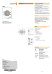
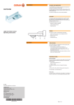
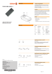
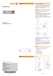
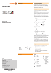
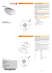
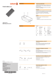
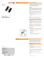
Description Function and application The “SOLAR” presence sensor detects the presence of people and measures the intensity of ambient light. The energy supply for the presence sensor is provided by solar cells or, if daylight or artificial light is insufficient, by batteries. SOLAR The radio control system is primarily used to extend existing electrical installations without additional cabling. Function The values measured by the presence sensor (motion, light value) are transmitted to the “Switch RC” radio receiver via a radio signal. The measured light value depends on the incidence of daylight, the artificial lighting and the properties of the surface (light/dark). The presence sensor is only ensured to function in combination with the radio receiver. All switching functions and parameter settings of the presence sensor are executed via the radio receiver. The following parameters can be set for every presence sensor programmed for the radio receiver: • Delay (switch-off delay time if no motion is detected) • Light value • Mode Presence sensor (light and motion sensor) Operating instructions Note: More information on the parameter settings can be found in the separate instructions for the „Switch RC“ radio receiver. Energy supply from solar cells/batteries If daylight or artificial light is sufficient, the sensor is powered by solar cells. For immediate operation, the energy storage unit must first be charged for approx. 5 minutes at a minimum of 50 – 100 lux. For light value measurement to function properly, the energy storage unit must be charged for several days at a minimum of 50 – 100 lux. The “Test” button can be used to check the operational readiness of the presence sensor; see “Testing the operational readiness”. The presence sensor can optionally be operated with batteries if, for example, the sensor is located in a room with a very low light value (< 50 lux). Construction A The presence sensor is made up of the following components: • “ LRN” button (A) for programming the presence sensor for the radio receiver G • Taste “Test”LRN button (B) for sending a test signal E B • Light sensor (C) Taste Test • Motion sensor (D) Lichtsensor F C • Solar cells (E) Test • LED “Test” LED (F) for monitoring the operational readiness • Housing (G) with battery compartment E D Operation Note The presence sensor cannot be used to manually switch the lighting on and off. Because all switching functions and parameter settings of the presence sensor are executed via the “Switch RC” radio receiver, the function of the presence sensor is only ensured in combination with the radio receiver. Programming the sensor for the radio receiver The presence sensor can be programmed for a radio receiver and can be deleted again. Proceed as follows: II 2009 SOLAR_ba0902en_we1.01.indd OSRAM GmbH Kunden Service Center Customer-Service-Center (CSC) Steinerne Furt 62 86167 Augsburg Germany Activate the programming mode of the radio receiver; see the separate instructions of the “Switch RC” radio receiver. Press the “LRN” button. Then proceed as follows if persons were located within the detection area when the presence sensor was being programmed: Ensure that all persons leave the detection area of the pres- Tel : +49 (0) 1803 677 - 200 (kostenpflichtig / charges apply) Fax.: +49 (0) 1803 677 - 202 www.osram.com www.osram.de 40083213856280 4008321385628 ence sensor. Enter the detection area again after at least 2 minutes elapse. Result: The presence sensor sends an ON signal and functions properly. Continued on the back page! Testing the operational readiness Operation (cont.) For solar operation, the energy storage unit must be sufficiently charged; see “Energy supply via solar cells/batteries”. To check the operational readiness, proceed as follows: Press the “Test” button. The presence sensor sends a test signal. Check whether the “Test” LED is lit up. • LED is lit: the presence sensor is operational. • LED is not lit: the presence sensor is not operational. Continue charging the energy storage unit if the presence sensor is not yet operational. Replacing the batteries The batteries need to be replaced every 5 – 7 years. Proceed as follows: Open the battery compartment on the back of the presence sensor. Remove the old batteries. I nsert the new batteries (1.5 V Micro AAA), ensuring that the polarity is correct. Troubleshooting If you cannot remedy the fault, please contact the customer service department of the manufacturer. The device is not functional. Is the energy storage unit sufficiently charged? The device is functional, but the switching functions are not being carried out. • Is the device correctly programmed for the radio receiver? Note: See the separate instructions for the “Switch RC” radio receiver. • Is the radio receiver switched off? • Has the functional range been exceeded? • Are the radio signals being disturbed by metal objects? The device is carrying out an undesired functional mode. Is the “Mode” parameter on the radio receiver set correctly? Note: See the separate instructions for the “Switch RC” radio receiver. The setpoints of the functions are not being reached. Are the “Time” and “Light value” parameters on the radio receiver set correctly? Note: See the separate instructions for the “Switch RC” radio receiver. Appendix Technical data Transmission frequency 868.3 MHz Power supply Solar cells (min. 50 - 100 lx) 2 batteries (to 50 lx) • 1.5 V Micro AAA • Service life: 5 – 7 years Charge time for immediate operation Approx. 5 – 10 minutes Operating temperature +10 °C … +50 °C Protection class IP 50 Dimensions (L x W x H) 108 x 108 x 26.8 mm Functional range Wood / drywall: 30 m (max. 5 walls) Masonry: 20 m (max. 3 walls) Reinforced concrete: 10 m (max. 1 wall/ceiling) Dimensioned drawing The EMC requirements to EN 60669-2-1 are fulfilled. Conformity with the relevant EU directives is confirmed by the CE symbol.