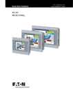
1
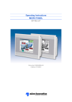
Operating Instructions
MICRO PANEL
XV200 5.7"; MK2 5.7"
Document M001089-06
Edition 03/2008
Imprint
MICRO PANEL XV200 5.7"; MK2 5.7"
Manufacturer
Product Company
Micro Innovation AG
Spinnereistrasse 8-14
CH-9008 St. Gallen
Switzerland
Sales Company
Micro Innovation GmbH
Nideggerstrasse 6-10
D-53115 Bonn
Germany
Service/Repair Center
Micro Innovation GmbH
Carl-Benz-Strasse 19
D-78224 Singen
Germany
Tel. +41 (0) 71 243 24 24
Fax +41 (0) 71 243 24 90
[email protected]
www.microinnovation.com
Tel. +49 (0) 228 602 2020
Fax +49 (0) 228 602 1713
[email protected]
www.microinnovation.com
Tel. +49 (0) 7731 7896 110
Fax +49 (0) 7731 7896 101
[email protected]
www.microinnovation.com
Original instructions
The German version of this document is the original instructions.
Translation of the original instructions
All non-German editions of this document are translations of the original instructions.
Editor
Monika Jahn
Brand and product names
All brand and product names are trademarks or registered trademarks of the owner concerned.
Copyright
© Micro Innovation AG, CH-9008 St. Gallen
All rights reserved, also for the translation.
None of this document may be reproduced or processed, duplicated or distributed by electronic
systems in any form (print, photocopy, microfilm or any other process) without the written permission of
Micro Innovation AG, St. Gallen.
Subject to modifications.
2
M001089-06, 03/2008
MICRO PANEL XV200 5.7"; MK2 5.7"
Contents
Contents
M001089-06, 03/2008
1.
1.1
1.2
General.......................................................................................................................
Purpose of these Operating Instructions.....................................................................
Additional documentation............................................................................................
5
5
5
2.
2.1
2.2
2.3
2.4
2.5
2.6
2.7
Device description ....................................................................................................
Device names .............................................................................................................
Function ......................................................................................................................
Intended use ...............................................................................................................
Device versions...........................................................................................................
Scope of delivery.........................................................................................................
Accessories.................................................................................................................
Designation .................................................................................................................
7
7
7
7
8
9
9
9
3.
3.1
3.2
3.3
3.3.1
3.3.2
3.3.3
3.3.4
3.3.5
3.3.6
3.4
Safety regulations .....................................................................................................
General .......................................................................................................................
Meaning of symbols ....................................................................................................
Mandatory requirements, personnel ...........................................................................
Work safety .................................................................................................................
Qualification of personnel............................................................................................
Operating Instructions .................................................................................................
Installation, maintenance and disposal .......................................................................
Prohibited use .............................................................................................................
Requirements for proper operation .............................................................................
Device related hazards ...............................................................................................
11
11
11
12
12
12
12
12
12
13
14
4.
4.1
Operating and indication elements .........................................................................
Overview .....................................................................................................................
17
17
5.
5.1
5.1.1
5.2
5.2.1
5.3
5.3.1
5.3.2
5.3.3
5.3.4
5.3.5
5.3.6
5.3.7
5.3.8
5.4
5.4.1
Installation .................................................................................................................
Safety regulations .......................................................................................................
Qualification of personnel............................................................................................
Requirements for the place of installation ...................................................................
Requirements for the mounting position .....................................................................
Cable preparation........................................................................................................
Overview of interfaces.................................................................................................
Preparation of cables with D-Sub connector...............................................................
Power supply...............................................................................................................
System Port (RS232) ..................................................................................................
Ethernet.......................................................................................................................
USB Device.................................................................................................................
CAN.............................................................................................................................
Profibus .......................................................................................................................
Mounting .....................................................................................................................
Mounting the device ....................................................................................................
19
19
19
20
20
21
22
23
25
26
27
28
29
31
34
35
3
Contents
4
MICRO PANEL XV200 5.7"; MK2 5.7"
6.
6.1
6.1.1
6.2
6.3
Operation ...................................................................................................................
Safety regulations .......................................................................................................
Qualification of personnel............................................................................................
Starting the device ......................................................................................................
Switching off the device ..............................................................................................
39
39
39
40
41
7.
7.1
7.1.1
7.2
7.2.1
7.2.2
7.2.3
7.3
7.3.1
7.4
Maintenance and service..........................................................................................
Safety regulations .......................................................................................................
Qualification of personnel............................................................................................
Maintenance................................................................................................................
Cleaning the resistive touch ........................................................................................
Recalibrating a resistive touch ....................................................................................
Battery.........................................................................................................................
Service ........................................................................................................................
Repairs........................................................................................................................
Troubleshooting and fault rectification ........................................................................
43
43
43
44
44
44
44
45
45
46
8.
8.1
8.1.1
8.2
8.3
8.4
Storage, transport and disposal ..............................................................................
Safety regulations .......................................................................................................
Qualification of personnel............................................................................................
Storage........................................................................................................................
Transport.....................................................................................................................
Disposal ......................................................................................................................
49
49
49
49
49
50
9.
9.1
9.2
9.3
9.4
9.5
9.5.1
9.6
9.7
9.8
9.9
Technical data ...........................................................................................................
Dimensions and weights .............................................................................................
Display ........................................................................................................................
Touch sensor ..............................................................................................................
System ........................................................................................................................
Interfaces ....................................................................................................................
Power supply...............................................................................................................
IP protection classes ...................................................................................................
Approvals and declarations.........................................................................................
Applicable standards and regulations .........................................................................
Ambient conditions......................................................................................................
51
51
52
52
53
53
54
54
54
55
55
M001089-06, 03/2008
MICRO PANEL XV200 5.7"; MK2 5.7"
1. General
1.
General
1.1
Purpose of these Operating Instructions
These Operating Instructions contain the information required for the correct and safe use of the
MICRO PANELs XV200 5.7"; MK2 5.7". The Operating Instructions are part of the devices and must
therefore be kept nearby.
These Operating Instructions describe all aspects of the devices: transport, installation, commissioning,
operation, maintenance, storage and disposal.
The operating system and the application software are not described.
!
Read the Chapter 3. Safety regulations, " 11, before working with the device. These contain important information for your personal safety. This chapter must be read and understood by all persons working with this device.
WARNING
Incomplete copy of these Operating Instructions
Working with individual pages of these Operating Instructions may cause damage
to property or personnel by failure to observe safety-related information.
! Always work with the complete document.
Comments about these
Operating Instructions
Please send any comments, recommendations or suggestions relating to these Operating Instructions
to [email protected].
1.2
Additional documentation
The following documents may be helpful in the use of the device in addition to these Operating Instructions. These can be downloaded from our home page (www.microinnovation.com/en, «DOWNLOADS»
section).
[1] M000174
System Description Windows CE
(operation of the Windows CE operating system on a MICRO PANEL)
[2] M000138
System Description Networks in Brief
(information on networks in general and on the integration of PCs and MICRO PANELs in
networks)
M001089-06, 03/2008
5
1. General
6
MICRO PANEL XV200 5.7"; MK2 5.7"
M001089-06, 03/2008
MICRO PANEL XV200 5.7"; MK2 5.7"
2.
Device description
2.1
Device names
2. Device description
XV200 5.7"; MK2 5.7" are two different names of equivalent products.
2.2
Function
MICRO PANELs XV200 5.7"; MK2 5.7" can be used exclusively as HMI devices or also as PLC devices.
2.3
Intended use
MICRO PANELs XV200 5.7"; MK2 5.7" are primarily used in machine and system building as well as
in building services management systems. They are designed exclusively for the visualization, operation and control of machines, systems and buildings. Any other use must be agreed beforehand with
the manufacturer.
M001089-06, 03/2008
7
2. Device description
2.4
MICRO PANEL XV200 5.7"; MK2 5.7"
Device versions
Fig. 1 XV200, MK2
MICRO PANELs XV200 5.7"; MK2 5.7" are available in the following versions:
Version with
XV200 type
MK2 type
# Monochrome display
# RS232 interface, not electrically isolated
XV-232-57BAS
MK2-232-57BAS
# Monochrome display
# Profibus interface, not electrically isolated
XV-230-57MPN
MK2-230-57MPN
# Monochrome display
# CAN interface, not electrically isolated
XV-230-57CNN
MK2-230-57CNN
# Color display
# RS232 interface, not electrically isolated
# Profibus interface, not electrically isolated
XV-252-57MPN
MK2-252-57MPN
# Color display
# RS232 interface, not electrically isolated
# CAN interface, not electrically isolated
XV-252-57CNN
MK2-252-57CNN
Tab. 1 Device versions
8
M001089-06, 03/2008
MICRO PANEL XV200 5.7"; MK2 5.7"
2.5
2. Device description
Scope of delivery
The scope of delivery of the MICRO PANELs XV200 5.7"; MK2 5.7" consists of the following:
Qty
Designation
1
MICRO PANEL:
# XV-232-57BAS or
# XV-230-57MPN or
# XV-230-57CNN or
# XV-252-57MPN or
# XV-252-57CNN
8
Retaining brackets for mounting the device
8
Threaded pins for mounting the device
1
Sealing strip for mounting the device
1
Power supply connector
1
Touch pen
#
#
#
#
#
MK2-232-57BAS or
MK2-230-57MPN or
MK2-230-57CNN or
MK2-252-57MPN or
MK2-252-57CNN
Tab. 2 Scope of delivery
2.6
Accessories
Different accessories are available.
!
Order the accessories required from your supplier.
2.7
Designation
Nameplate
A nameplate is fixed on the rear of the device in order to identify it. The nameplate contains the following
information:
# Manufacturer address
# Type designation
# Power supply required
# Article no.
# Serial no.
# Time of manufacturing (week/year)
# Approval marks
# Arrangement of interfaces and operating elements
# Permissible mounting options (top edge «Top»)
Support
To ensure fast and optimum support always provide the support personnel with the following information on the nameplate:
# Article no.
# Serial no.
M001089-06, 03/2008
9
2. Device description
10
MICRO PANEL XV200 5.7"; MK2 5.7"
M001089-06, 03/2008
MICRO PANEL XV200 5.7"; MK2 5.7"
3. Safety regulations
3.
Safety regulations
3.1
General
Hazards may still occur even though the device meets the current state of the art and complies with all
recognized safety requirements.
The device must only be installed and commissioned in perfect technical condition and in compliance
with these Operating Instructions.
!
3.2
Read this chapter, before working with the device. This contains important information
for your personal safety. This chapter must be read and understood by all persons working with this device.
Meaning of symbols
The following symbols are used in these Operating Instructions according to the hazard level described:
DANGER
Signal word DANGER
Indicates an imminently hazardous situation which, if not avoided, will result in death
or serious injury.
WARNING
Signal word WARNING
Indicates a potentially hazardous situation which, if not avoided, could result in death
or serious injury.
CAUTION
Signal word CAUTION
Indicates a potentially hazardous situation which, if not avoided, could result in minor
or moderate injury or in material damage.
!
Indicates important information not related to safety.
The danger symbol used and the text indicate the actual danger and the related preventative measures.
M001089-06, 03/2008
11
3. Safety regulations
MICRO PANEL XV200 5.7"; MK2 5.7"
3.3
Mandatory requirements, personnel
3.3.1
Work safety
All applicable work safety regulations (in-house and national) must be observed.
3.3.2
Qualification of personnel
It must be ensured that only suitably qualified persons work with the device. These persons must be
informed of all hazards and risks associated with the device.
The following persons must be suitably qualified according to the work to be completed:
# Installation:
Automation specialists
# General operation:
Operating personnel instructed in the application
# Maintenance and service:
Persons suitably qualified for the work to be completed
# Storage:
Persons without special knowledge
# Transport:
Persons with a specialist knowledge of transport (in particular how to prevent damage in transit)
# Disposal:
Persons with a specialist knowledge of proper disposal (also about the proper disposal of harmful
substances)
3.3.3
Operating Instructions
It must be ensured that any person working with the device in any phase of its lifespan has read and
understood the relevant sections of the Operating Instructions.
WARNING
Incomplete copy of these Operating Instructions
Working with individual pages of these Operating Instructions may cause damage
to property or personnel by failure to observe safety-related information.
! Always work with the complete document.
3.3.4
Installation, maintenance and disposal
It must be ensured that the device is properly connected, mounted, maintained and disposed of in
compliance with all relevant standards and safety regulations.
3.3.5
Prohibited use
The implementation of safety functions (relating to the protection of personnel and machinery) using the
device is prohibited.
12
M001089-06, 03/2008
MICRO PANEL XV200 5.7"; MK2 5.7"
3.3.6
3. Safety regulations
Requirements for proper operation
The following points must be observed so that the device meets the contractual requirements:
# Only qualified personnel may work with the device.
# These persons must have read the Operating Instructions and must observe the requirements
described.
# The ambient conditions stated must be observed. See Chapter 9.9 Ambient conditions, " 55.
# The maintenance work must be carried out correctly.
No liability is accepted for damage, consequential damage and accidents caused by the following:
Failure to observe work safety regulations
Failure or malfunction of the device
Improper handling or use
Failure to observe the Operating Instructions
Conversions, modifications and repairs to the device
#
#
#
#
#
!
M001089-06, 03/2008
Repairs, see Chapter 7.3.1 Repairs, " 45.
13
3. Safety regulations
3.4
MICRO PANEL XV200 5.7"; MK2 5.7"
Device related hazards
DANGER
Explosion hazard
Death, serious injury or material damage may occur if an electrical plug connection
is removed in a potentially explosive atmosphere during operation.
! Only use the device in the following environments:
- Environments not subject to explosion hazards
- Potentially explosive atmosphere, Zone 22 (according to ATEX 94/9/EC)
! Only operate the device in potentially explosive atmospheres if it is correctly
mounted.
! Switch off the device before removing the plug connections
WARNING
Live parts in the device
When the device is opened, there is a risk of electric shock if live parts are touched.
! The device must not be opened.
WARNING
Potential equalization currents
Large equalization currents between the protective ground systems of different devices may cause operational malfunctions due to signal interference and may even
cause fires.
! If necessary, a potential equalization conductor should be installed parallel to the
cable. This should have a cross-section that is a multiple of the cable shield.
CAUTION
Sensitive resistive touch surface
Damage to the resistive touch due to the use of pointed or sharp objects.
! Only activate the resistive touch with your finger or a touch pen.
! When wearing gloves, ensure that these are clean. They must not be covered
with abrasive dust or sharp particles.
14
M001089-06, 03/2008
MICRO PANEL XV200 5.7"; MK2 5.7"
3. Safety regulations
CAUTION
Electrostatic discharge
Electrostatic discharge may damage or destroy electronic components.
! Avoid contact with components (such as connector pins) that are susceptible to
electrostatic discharge.
! Discharge (by touching a grounded metal object) any static charge accumulated
in your body before touching the device.
CAUTION
Data loss
During a write operation, the CF card may lose data or may be destroyed if it is removed or if there is a power failure.
! Only insert the CF card when the device is in a de-energized state.
! Always secure CF cards with the CF slot lock mechanism.
! Avoid write operations to CF cards. Reasons:
- The number of write cycles possible on CF cards is limited.
- A power failure during write operations will most likely lead to loss of data.
! Only remove the CF card when the device is in a de-energized state.
! Before switching off, ensure that no software write operations to the CF card are
in progress.
CAUTION
Device condensation
If the device is or was exposed to climatic changes (temperature fluctuation, air humidity) moisture can form on or in the device (device condensation). In this case,
there is a risk of short-circuit.
! The device must not be switched on when device condensation is present.
! If condensation is present on the device, or if it was exposed to temperature fluc-
tuations, it must be allowed to adjust to room temperature (do not expose the device to the direct heat of heating devices) prior to commissioning.
CAUTION
Cleaning the device
Damage to the device due to the use of pointed or sharp objects or by liquids.
! Do not use any pointed or sharp objects (e.g. knife) for cleaning.
! Do not use any aggressive or abrasive cleaning agent or solvent.
! Avoid any liquid entering the device (risk of short-circuit).
M001089-06, 03/2008
15
3. Safety regulations
16
MICRO PANEL XV200 5.7"; MK2 5.7"
M001089-06, 03/2008
MICRO PANEL XV200 5.7"; MK2 5.7"
4. Operating and indication elements
4.
Operating and indication elements
4.1
Overview
A
B
C,D
E
Fig. 2 Operating and indication elements
The device has the following operating and indication elements:
Element
Function
A CF slot lock mechanism
Fastening the CF card in the CF slot.
B CF slot 0
Slot for CF card with operating system and normally with PLC and visualization projects.
C Display
Display operating and indication elements.
D Touch sensor
Resistive touch:
Detection of the actuation of the operating elements shown on the
display. These devices are operated by touching the operating
elements with your finger or with a touch pen.
E Control button
Function depends on the software used.
Tab. 3 Operating and indication elements
M001089-06, 03/2008
17
4. Operating and indication elements
18
MICRO PANEL XV200 5.7"; MK2 5.7"
M001089-06, 03/2008
MICRO PANEL XV200 5.7"; MK2 5.7"
5. Installation
5.
Installation
5.1
Safety regulations
!
5.1.1
Read the Chapter 3. Safety regulations, " 11, before installing and commissioning the
device. These contain important information for your personal safety.
Qualification of personnel
The device must only be installed and commissioned by automation specialists.
M001089-06, 03/2008
19
5. Installation
5.2
5.2.1
MICRO PANEL XV200 5.7"; MK2 5.7"
Requirements for the place of installation
#
Approvals:
The device must only be used in locations that are approved for the device. See the markings on
the nameplate and Chapter 9. Technical data, " 51.
#
Power supply:
The power supply must comply with the requirements stated in Chapter 9.5.1 Power supply, " 54.
Requirements for the mounting position
The device is designed for mounting in control cabinets, control panels or control desks. It can be
mounted horizontally or vertically. The following requirements must be fulfilled when selecting a suitable
mounting position:
#
The display should not be exposed to direct sunlight (the UV component of sunlight reduces the
lifespan of the device).
#
If possible, the operating elements on the service side of the device and the cable connections
should also still be accessible after the device has been mounted.
#
The ambient conditions stated must be observed. See Chapter 9.9 Ambient conditions, " 55.
#
Sufficient ventilation (cooling) must be ensured by means of:
# Clearance of at least 3 cm to the ventilation slots
# Clearance of at least 15 cm from heat radiating components such as heavily loaded trans-
formers
# The expected temperatures should be within the permissible range. See Chapter 9.9 Ambient
conditions, " 55.
#
Properties of the mounting surfaces:
# Material thickness at the mounting cutout 2…5 mm
# Flatness ≤ 0.5 mm
(this requirement must also be fulfilled when the device is mounted!)
# Surface roughness Rz ≤ 120
20
M001089-06, 03/2008
MICRO PANEL XV200 5.7"; MK2 5.7"
5.3
5. Installation
Cable preparation
The cables for wiring the device are not supplied with it.
WARNING
Potential equalization currents
Large equalization currents between the protective ground systems of different devices may cause operational malfunctions due to signal interference and may even
cause fires.
! If necessary, a potential equalization conductor should be installed parallel to the
cable. This should have a cross-section that is a multiple of the cable shield.
CAUTION
Operational malfunctions
Use of unsuitable or improperly prepared cables, as well as incorrect wiring will
mean that neither the values stated in the technical data nor the electromagnetic
compatibility (EMC) can be ensured.
! Only use cables prepared by specialists.
! The cables used must be prepared according to the interface description in these
Operating Instructions.
! The wiring instructions for the relevant interface must be observed when wiring
the device.
! Any generally applicable regulations and standards must be fulfilled.
M001089-06, 03/2008
21
5. Installation
5.3.1
MICRO PANEL XV200 5.7"; MK2 5.7"
Overview of interfaces
Connector side:
A
B
C
D
Fig. 3 Connector side of the device (figure shows the device with the RS232 and CAN interface)
!
The fitting of the connector cover on the connector side depends on the device version
concerned. See nameplate and Chapter 2.4, " 8.
Service side:
E
F
G
Fig. 4 Service side of the device
Interface
Interface description
A Ethernet
→ Chapter 5.3.5, " 27
B CAN, depending on the device version
→ Chapter 5.3.7, " 29
B Profibus, depending on the device version
→ Chapter 5.3.8, " 31
C System Port, depending on the device version
→ Chapter 5.3.4, " 26
D Power supply
→ Chapter 5.3.3, " 25
E DIAG
Only for service tasks
F BFL (Boot Flash Lock)
Only for service tasks
G USB Device
→ Chapter 5.3.6, " 28
Tab. 4 Overview of interfaces
22
M001089-06, 03/2008
MICRO PANEL XV200 5.7"; MK2 5.7"
5.3.2
5. Installation
Preparation of cables with D-Sub connector
The preparation of bus cables is an essential factor in ensuring reliable operation and electromagnetic
compatibility (EMC).
Wiring requirements
#
#
#
The cables must be shielded.
The cable shield must be made from a copper braid.
The cable shield must make a low impedance connection with the connector casing over a large
contact area. This is achieved by:
# Use of metal or metallized connector casings with a cable clamp for strain relief.
# The cable clamp must be screwed securely to the connector.
Connecting the cable
shield
1
30 mm
2
3
5…8 mm
Fig. 5 Connecting the cable shield
M001089-06, 03/2008
1
Strip the cable end so that approx. 3 cm of the shield braid is exposed.
2
Fold back the shield braid over the cable shield.
3
Fit approx. 3 cm of heat shrinkable tubing over the folded back end of the shield braid or use a
rubber grommet.
# 5…8 mm of the shield braid must be exposed at the cable end.
# The folded back shield braid end must be covered by the heat shrinkable tubing or by the
rubber grommet.
4
Fit the D-Sub connector to the cable end:
# The exposed metal shield braid must be clamped to the connector casing with the cable clamp.
23
5. Installation
MICRO PANEL XV200 5.7"; MK2 5.7"
A
B
C
D
E
F
Fig. 6 Cable prepared with D-Sub connector
A Cable with cable sheath
B Heat shrinkable tubing or rubber grommet
C Cable clamp
!
24
D Shield braid
E D-Sub connector
F Fixing screw UNC
The EMC values stated in the technical data (immunity and emission) can only be guaranteed by observing the prescribed cable preparation!
M001089-06, 03/2008
MICRO PANEL XV200 5.7"; MK2 5.7"
5.3.3
5. Installation
Power supply
The device is provided with an internal self-resetting fuse and is protected against polarity reversal. The
GND terminal is connected exclusively to the connector cover and not to the 0 V. The housing is made
from plastic and is isolated. The device power supply is not electrically isolated.
The device requires a 24 VDC power supply from an AC/DC converter with safe isolation (e.g. SELV).
For other power supply requirements see Chapter 9.5.1 Power supply, " 54.
#
SELV (safety extra low voltage):
Circuit in which no dangerous voltage is present, even in the event of a single fault.
Fig. 7 Power supply interface
Wiring
#
Phoenix Contact MSTB 2.5/3-ST-5.08 connector, Phoenix order no. 1757022 is always supplied
with the device.
+24 VDC GND
0V
Fig. 8 Phoenix Contact MSTB 2.5/3-ST-5.08 connector (view from the wiring side)
Connection
Assignment
+24 VDC
+24 VDC power supply
GND
Functional ground connected with connector cover
(does not have to be connected)
0V
0 V power supply
Tab. 5 Assignment of connector
#
The following must be observed when the connector wiring is prepared:
Preparing the wiring of the connector
Terminal type
Pluggable screw terminal
Cross-section
# min. 0.75 mm2 / max. 2.5 mm2 (lead or wire)
# min. AWG18 / max. AWG12
Stripping length
7 mm
Tab. 6 Preparing the wiring of the connector
M001089-06, 03/2008
25
5. Installation
5.3.4
MICRO PANEL XV200 5.7"; MK2 5.7"
System Port (RS232)
The System Port is implemented as a standard RS232 interface. This interface is not electrically
isolated.
1
3
2
6
8
7
5
4
9
Fig. 9 RS232 interface (9-pin, D-Sub, male, UNC)
Pin
Signal
Assignment
1
DCD
Data Carrier Detected
2
RxD
Receive Data
3
TxD
Transmit Data
4
DTR
Data Terminal Ready
5
GND
Ground
6
DSR
Data Set Ready
7
RTS
Request to Send
8
CTS
Clear to Send
9
RI
Ring Indicator
Tab. 7 Pin assignment of the RS232 interface
Wiring
#
#
Shielded cables must be used.
The maximum baud rate depends on the cable length:
Cable length
Max. baud rate
30 m
9600 Bit/s
15 m
19200 Bit/s
10 m
38400 Bit/s
5m
57600 Bit/s
2.5 m
115200 Bit/s
Tab. 8 Relationship of cable length / baud rate
!
26
When preparing the cables, ensure that there is a low-resistance connection between
the cable shield and the connector casing (→ Chapter 5.3.2, " 23).
M001089-06, 03/2008
MICRO PANEL XV200 5.7"; MK2 5.7"
5.3.5
5. Installation
Ethernet
LINK ACT
Fig. 10 Ethernet interface (RJ45 socket)
LED
Signal
Meaning
ACT (yellow)
flashes
Ethernet is active (data traffic)
LINK (green)
lit
Active network is connected and detected
Tab. 9 Control LEDs of the Ethernet interface
Cable
#
Use shielded twisted pair cable (STP) for networking:
# For device to device connection: crossover cable
# For connecting to the hub/switch: 1:1 patch cable
#
Maximum cable length: 100 m.
Ethernet interface in accordance with EIA/TIA 568 TSB-36.
CAUTION
Forces acting on the Ethernet interface
Communication can be disturbed and the connection mechanics damaged if the
Ethernet interface is exposed to severe vibration or the RJ45 plug connection is
pulled.
! Protect the RJ45 connection from severe vibration.
! Protect the RJ45 connection from pulling on the socket.
M001089-06, 03/2008
27
5. Installation
5.3.6
MICRO PANEL XV200 5.7"; MK2 5.7"
USB Device
The USB Device interface supports USB 1.1.
Fig. 11 USB Device interface (USB Device, type B)
Cable
28
#
#
Only use shielded USB standard cable.
Maximum cable length: 5 m.
M001089-06, 03/2008
MICRO PANEL XV200 5.7"; MK2 5.7"
5.3.7
5. Installation
CAN
The CAN interface is not electrically isolated.
1
2
6
4
3
7
8
5
9
Fig. 12 CAN interface (9-pin, D-Sub, male, UNC)
Pin
Signal
Assignment
1
-
nc
2
CAN-L
Bus line (dominant low)
3
CAN-GND
CAN Ground
4
-
nc
5
-
nc
6
GND
Optional CAN Ground
7
CAN-H
Bus line (dominant high)
8
-
nc
9
-
nc
Tab. 10 Pin assignment of CAN interface in accordance with CiA
!
Wiring
#
#
#
#
#
Pin 3 (CAN-GND) and 6 (GND) are connected internally in the device.
nc: Pins 1, 4, 5, 8 and 9 must not be connected!
The CAN bus drivers are fed internally with power.
No power supply for third-party devices is implemented on the CAN connector.
Shielded cables must be used.
Cable specifications
Rated surge impedance
120 Ω
Permissible surge impedance
108…132 Ω
Capacitance per unit length
< 60 pF/m
Core cross-section / max. cable length
≥ 0.25 mm2 / 100 m
≥ 0.34 mm2 / 250 m
≥ 0.75 mm2 / 500 m
Tab. 11 Cable specifications
M001089-06, 03/2008
29
5. Installation
MICRO PANEL XV200 5.7"; MK2 5.7"
#
The maximum baud rate depends on the cable length:
Cable length
Max. baud rate
40 m
1000 Kbit/s
50 m
800 Kbit/s
100 m
500 Kbit/s
250 m
250 Kbit/s
500 m
125 Kbit/s
500 m
100 Kbit/s
1000 m
50 Kbit/s
2500 m
20 Kbit/s
5000 m
10 Kbit/s
Tab. 12 Relationship of cable length / baud rate
!
CAN bus topology
# The use of repeaters is recommended with cables over 1000 m in length. Repeaters
can also be used to implement electrical isolation. Refer to the documentation of the
repeater manufacturer for further information.
# Observe the recommendations of the CiA (CAN in Automation).
# When preparing the cables, ensure that there is a low-resistance connection between
the cable shield and the connector casing (→ Chapter 5.3.2, " 23).
#
A bus segment can connect up to 32 bus stations.
#
Several bus segments can be linked via repeaters (bidirectional amplifiers). Refer to the documentation of the repeater manufacturer for further information.
#
A bus segment must be provided with cable termination (120 Ω) at both ends. These terminations
must be connected in the connector, directly between pin 2 and 7.
!
# The bus segment must be terminated at both ends.
# No more than two terminations must be provided on each bus segment.
# Transmission faults can occur if operation is carried out without the correct termina-
tion.
1
CAN-L
CAN-H
2
3
4
5
6
7
120
8
9
Fig. 13 Termination
30
M001089-06, 03/2008
MICRO PANEL XV200 5.7"; MK2 5.7"
5.3.8
5. Installation
Profibus
The Profibus interface is not electrically isolated.
5
4
9
3
8
1
2
7
6
Fig. 14 Profibus interface (9-pin, D-Sub, female, UNC)
Pin
Signal
Assignment
1
Internal termination for line B
2
EIA RS 485 line B (alternative)
3
B
EIA RS 485 line B (Profibus standard)
4
RTSAS
Output for controlling a repeater
5
M5EXT
Output of reference ground for external termination
6
P5EXT
5V output for external termination
7
EIA RS 485 line A (alternative)
8
A
9
EIA RS 485 line A (Profibus standard)
Internal termination for line A
Tab. 13 Pin assignment of the Profibus interface
!
Wiring
#
Pin 6 (5 V) must not be used as a power supply for external devices.
Shielded twisted pair cables, cable type A (in accordance with Profibus standard EN50170) must
be used.
Cable specifications
Rated surge impedance
150 Ω
Permissible surge impedance
135…165 Ω
Capacitance per unit length
< 30 pF/m
Loop resistance
< 110 Ω/km
Core cross-section
≥ 0.34 mm2 (22 AWG)
Tab. 14 Cable specifications
M001089-06, 03/2008
31
5. Installation
MICRO PANEL XV200 5.7"; MK2 5.7"
#
The maximum baud rate depends on the cable length:
Cable length
Max. baud rate
1200 m
≤ 93.75 Kbit/s
1000 m
187.5 Kbit/s
400 m
500 Kbit/s
200 m
1500 Kbit/s
Tab. 15 Relationship of cable length / baud rate (for cables compliant with cable type A of the Profibus standard EN5017)
!
Profibus topology
When preparing the cables, ensure that there is a low-resistance connection between
the cable shield and the connector casing (→ Chapter 5.3.2, " 23).
#
A bus segment can connect up to 32 bus stations.
#
Several bus segments can be linked via repeaters (bidirectional amplifiers). Refer to the documentation of the repeater manufacturer for further information.
!
The maximum cable length can be increased by using repeaters. Refer to the documentation of the repeater manufacturer for further information.
#
Bus terminal connector
Only use bus terminal connectors that are specified for use in the Profibus network. They hold both
bus cables on a bus station and ensure a low impedance connection of the cable shield to the
shield reference potential of the bus station.
These bus terminal connectors contain the Profibus cable termination that can be switched on as
required.
#
A bus segment must be provided with cable termination at both ends. The termination is passive
and is fed from the bus station. It ensures a defined idle signal on the bus when no bus station is
transmitting.
These bus terminations should be implemented externally in the connector casing according to the
Profibus standard (they can also be implemented with the bus terminating connector described
above).
Alternatively, the termination can be implemented using jumpers between Pin 1 and 2, Pin 7 and 9.
1
2
B
A
3
4
5
Fig. 15 Internal termination
32
6
7
8
9
390
1
2
6
390
3
7
8
4
5
9
220
B
A
Fig. 16 External termination
M001089-06, 03/2008
MICRO PANEL XV200 5.7"; MK2 5.7"
!
M001089-06, 03/2008
5. Installation
#
#
#
#
The bus segment must be terminated at both ends.
No more than two terminations must be provided on each bus segment.
At least one of the two terminations must be fed by the bus station.
Transmission faults can occur if operation is carried out without the correct termination on the Profibus network.
33
5. Installation
5.4
MICRO PANEL XV200 5.7"; MK2 5.7"
Mounting
CAUTION
Operational malfunctions
Use of unsuitable or improperly prepared cables, as well as incorrect wiring will
mean that neither the values stated in the technical data nor the electromagnetic
compatibility (EMC) can be ensured.
! Only use cables prepared by specialists.
! The cables used must be prepared according to the interface description in these
Operating Instructions.
! The wiring instructions for the relevant interface must be observed when wiring
the device.
! Any generally applicable regulations and standards must be fulfilled.
CAUTION
Device condensation
If the device is or was exposed to climatic changes (temperature fluctuation, air humidity) moisture can form on or in the device (device condensation). In this case,
there is a risk of short-circuit.
! The device must not be switched on when device condensation is present.
! If condensation is present on the device, or if it was exposed to temperature fluc-
tuations, it must be allowed to adjust to room temperature (do not expose the device to the direct heat of heating devices) prior to commissioning.
1
Check the device for damage in transit.
!
2
3
The device must only be installed and commissioned in perfect technical condition and
in compliance with these Operating Instructions.
Mount the device in the control cabinet, control panel or the control desk. See Chapter 5.4.1
Mounting the device, " 35.
Connect the device as required.
# Follow the instructions on wiring the relevant interface. See Chapter 5.3 Cable preparation,
" 21.
!
34
The device is not provided with an On/Off switch. If the power supply is not provided
with a switch, the device will start up (boot) as soon as it is connected to the power supply.
M001089-06, 03/2008
MICRO PANEL XV200 5.7"; MK2 5.7"
Mounting the device
1
Select the mounting position of the device as described in Chapter 5.2.1 Requirements for the
mounting position, " 20.
2
Prepare a mounting cutout for the device at the selected position:
# Mounting cutout 198 × 142 mm (±1 mm)
# Material thickness at the mounting cutout 2…5 mm
142,0 +1/-1
5.4.1
5. Installation
198,0 +1/-1
Fig. 17 Mounting cutout for 5.7" devices
3
Insert the sealing strip supplied in the groove (A) on the rear of the device front plate and cut it so
that the join is tight.
# Groove for sealing strip, see Fig. 18, " 36.
CAUTION
Poor sealing
Poor sealing resulting from the twisting of the sealing strip or due to a gap between
the ends of the sealing strip.
! The join of the sealing strip must be positioned on the bottom of the device.
! Do not twist the sealing strip when it is inserted.
! Cut the sealing strip to a suitable length so that the join is tight.
M001089-06, 03/2008
35
5. Installation
MICRO PANEL XV200 5.7"; MK2 5.7"
A
Fig. 18 Groove for sealing strip (A)
4
Fit the supplied threaded pins in the retaining brackets beforehand.
# The tips of the threaded pins must point towards the wider ends of the retaining brackets.
Fig. 19 Threaded pin pre-fitted in a retaining bracket
5
Fit the device from the front into the mounting cutout.
6
Clip on the retaining brackets in the recesses provided for them on the device as shown below and
fix the device by tightening the threaded pins.
CAUTION
Mechanical damage to the device
Tightening the threaded pins too tightly may damage the device.
! Tighten threaded pins with a max. tightening torque of 0.15 Nm.
!
36
The positions of the retaining brackets depend on the mounting requirements.
M001089-06, 03/2008
MICRO PANEL XV200 5.7"; MK2 5.7"
5. Installation
# Standard mounting:
# Top and bottom of the device:
Fit one retaining bracket each at the left and right fixing position
Fig. 20 Device with four retaining brackets (does not meet IP65 requirements)
# Devices which must be mounted in accordance with IP65 or used in potentially explosive atmo-
spheres:
# Top and bottom of the device:
One retaining bracket at each of the fixing positions (left, right and in the center)
# Left and right on the device:
One retaining bracket each at the central fixing position
Fig. 21 Device with eight retaining brackets (meets IP65 requirements)
M001089-06, 03/2008
37
5. Installation
38
MICRO PANEL XV200 5.7"; MK2 5.7"
M001089-06, 03/2008
MICRO PANEL XV200 5.7"; MK2 5.7"
6. Operation
6.
Operation
6.1
Safety regulations
!
Read the Chapter 3. Safety regulations, " 11, before working with the device. These contain important information for your personal safety.
CAUTION
Sensitive resistive touch surface
Damage to the resistive touch due to the use of pointed or sharp objects.
! Only activate the resistive touch with your finger or a touch pen.
! When wearing gloves, ensure that these are clean. They must not be covered
with abrasive dust or sharp particles.
CAUTION
Device condensation
If the device is or was exposed to climatic changes (temperature fluctuation, air humidity) moisture can form on or in the device (device condensation). In this case,
there is a risk of short-circuit.
! The device must not be switched on when device condensation is present.
! If condensation is present on the device, or if it was exposed to temperature fluc-
tuations, it must be allowed to adjust to room temperature (do not expose the device to the direct heat of heating devices) prior to commissioning.
6.1.1
Qualification of personnel
The device must only be operated by operating personnel instructed for the application concerned.
M001089-06, 03/2008
39
6. Operation
6.2
MICRO PANEL XV200 5.7"; MK2 5.7"
Starting the device
1
Insert the CF card with the operating system:
CAUTION
Data loss
During a write operation, the CF card may lose data or may be destroyed if it is removed or if there is a power failure.
! Only insert the CF card when the device is in a de-energized state.
! Always secure CF cards with the CF slot lock mechanism.
! Avoid write operations to CF cards. Reasons:
- The number of write cycles possible on CF cards is limited.
- A power failure during write operations will most likely lead to loss of data.
! Only remove the CF card when the device is in a de-energized state.
! Before switching off, ensure that no software write operations to the CF card are
in progress.
Fig. 22 Service side of the device
1.1
Open the CF slot lock mechanism.
1.2
Insert the CF card into the CF slot.
!
1.3
2
Do not apply any force (CF cards are protected against reverse insertion).
Close the CF slot lock mechanism.
Energize the device.
# The device will boot.
3
If the device does not boot up and/or if an error message appears while starting (booting) the
device, see Chapter 7.4 Troubleshooting and fault rectification, " 46.
4
Complete the following steps after initial commissioning (→ Document «M000174»):
4.1
Adjust the system settings of the device.
4.2
Install the required application programs.
!
40
The lifespan of the backlight can be increased by reducing the brightness (→ Document
«M000174»).
M001089-06, 03/2008
MICRO PANEL XV200 5.7"; MK2 5.7"
6.3
6. Operation
Switching off the device
CAUTION
Data loss
During a write operation, the CF card may lose data or may be destroyed if it is removed or if there is a power failure.
! Only insert the CF card when the device is in a de-energized state.
! Always secure CF cards with the CF slot lock mechanism.
! Avoid write operations to CF cards. Reasons:
- The number of write cycles possible on CF cards is limited.
- A power failure during write operations will most likely lead to loss of data.
! Only remove the CF card when the device is in a de-energized state.
! Before switching off, ensure that no software write operations to the CF card are
in progress.
!
1
M001089-06, 03/2008
Frequent on/off switching of the device, especially at low temperatures, will reduce the
lifespan of the cold cathode tubes (CCFL) of the backlight.
# Avoid frequent on/off switching of the device.
# Reduce the brightness of the backlight instead (→ Document «M000174»).
De-energize the device.
41
6. Operation
42
MICRO PANEL XV200 5.7"; MK2 5.7"
M001089-06, 03/2008
MICRO PANEL XV200 5.7"; MK2 5.7"
7. Maintenance and service
7.
Maintenance and service
7.1
Safety regulations
!
7.1.1
Read the Chapter 3. Safety regulations, " 11, before working with the device. These contain important information for your personal safety.
Qualification of personnel
The device should only be maintained and serviced by persons with the following qualifications,
according to the task required:
#
Cleaning:
# Operating personnel
#
Troubleshooting:
# Persons with the specific knowledge required
#
Repairs:
# See Chapter 7.3.1 Repairs, " 45
M001089-06, 03/2008
43
7. Maintenance and service
7.2
MICRO PANEL XV200 5.7"; MK2 5.7"
Maintenance
Resistive touch devices are maintenance-free. However, the following work may be necessary:
Cleaning of the resistive touch if contaminated.
Recalibration of the resistive touch if it does not respond correctly to touch operation.
#
#
7.2.1
Cleaning the resistive touch
CAUTION
Cleaning the device
Damage to the device due to the use of pointed or sharp objects or by liquids.
! Do not use any pointed or sharp objects (e.g. knife) for cleaning.
! Do not use any aggressive or abrasive cleaning agent or solvent.
! Avoid any liquid entering the device (risk of short-circuit).
1
7.2.2
Clean the resistive touch carefully with a clean, damp cloth.
# With stubborn contamination, spray a little cleaning agent onto the damp cloth first of all.
Recalibrating a resistive touch
The resistive touch is already calibrated when delivered. However, it must be recalibrated if it does not
respond correctly to touch operation. Touch calibration, see Document «M000174».
7.2.3
Battery
The integrated battery cannot be exchanged. Lifespan, see Chapter 9.4 System, " 53.
44
M001089-06, 03/2008
MICRO PANEL XV200 5.7"; MK2 5.7"
7.3
Service
7.3.1
Repairs
7. Maintenance and service
Repairs must only be carried out by the manufacturer or from a repair center authorized by the manufacturer.
Contact your local dealer or the technical support of the device manufacturer. Contact address, see
Section «Manufacturer», " 2.
Only the original packaging should be used for transporting the device.
M001089-06, 03/2008
45
7. Maintenance and service
7.4
MICRO PANEL XV200 5.7"; MK2 5.7"
Troubleshooting and fault rectification
Fault and possible cause
Corrective action
Device does not start (boot).
Power supply interface does not have any
power.
Check the power supply cable.
While the device is starting (booting),
the following message appears:
«No Card in CF slot 0 detected !!!»
The CF slot 0 does not contain a CF card.
Insert the CF card with the operating system in
the CF slot 0.
CF card in CF slot 0 could not be read
(faulty).
Replace CF card.
«Search Subdirectory … not found»
The CF card in CF slot 0 does not have an
OS (operating system).
# If the CF card does not contain an operating
system, load one onto a CF card.
# Insert the CF card with the operating system
in the CF slot 0.
«<50> Touch is dirty or defect»
(only appears if GALILEO is installed)
Resistive touch is not correctly calibrated.
# Start (boot) the device.
# Calibrate touch
(→ Document «M000174»).
The threaded pins for mounting the device
have been tightened too much.
Loosen the threaded pins (observe max.
torque, → Chapter 5.4.1, " 35).
Device is faulty.
Send in your device for repair.
Display remains or becomes dark.
Backlight is switched off.
Check the function in the visualization software.
Backlight is faulty.
Send in your device for repair.
Touch does not react or does not react correctly to
touch operation.
Resistive touch is not correctly calibrated.
# Start (boot) the device.
# Calibrate touch
(→ Document «M000174»).
Touch is deactivated.
# Start (boot) the device.
# Activate touch
(→ Document «M000174»).
46
M001089-06, 03/2008
MICRO PANEL XV200 5.7"; MK2 5.7"
7. Maintenance and service
Fault and possible cause
The icon
Corrective action
appears in the taskbar.
Incorrect operation of the operating elements
on the display.
Remove all objects (also fingers) from the area
of the display.
The threaded pins for mounting the device have
been tightened too much.
Loosen the threaded pins (observe max.
torque, → Chapter 5.4.1, " 35).
Device is faulty.
Send in your device for repair.
Tab. 16 Troubleshooting and fault rectification
M001089-06, 03/2008
47
7. Maintenance and service
48
MICRO PANEL XV200 5.7"; MK2 5.7"
M001089-06, 03/2008
MICRO PANEL XV200 5.7"; MK2 5.7"
8. Storage, transport and disposal
8.
Storage, transport and disposal
8.1
Safety regulations
!
8.1.1
Read the Chapter 3. Safety regulations, " 11, before installing and commissioning the
device. These contain important information for your personal safety.
Qualification of personnel
The device should only be stored, transported and disposed of by persons with the following qualifications, according to the task required.
# Storage:
Persons without special knowledge
# Transport:
Persons with a specialist knowledge of transport (in particular how to prevent damage in transit)
# Disposal:
Persons with a specialist knowledge of proper disposal (also about the proper disposal of harmful
substances)
8.2
Storage
The device should be stored in the original packaging. The ambient conditions must be fulfilled. See
Chapter 9.9 Ambient conditions, " 55.
8.3
Transport
Damage to the device must be prevented during transport. The device should therefore only be transported in the original packaging.
The ambient conditions must be fulfilled even when the device is transported. See Chapter 9.9 Ambient
conditions, " 55.
1
M001089-06, 03/2008
Check the device on arrival for damage in transit.
49
8. Storage, transport and disposal
8.4
MICRO PANEL XV200 5.7"; MK2 5.7"
Disposal
DANGER
Explosive and toxic materials
Any improper handling causes a risk of explosion due to the lithium battery soldered
in the device and a risk of poisoning due to the mercury content of the cold cathode
tubes.
! The device must only be disposed of by persons with the required specialist
knowledge.
Devices that are no longer used must be properly disposed of in accordance with the applicable national
regulations or returned to the manufacturer or sales office.
Materials used in the
device
Component
Material
Housing
ABS-PC
Front plate
ABS-PC
Resistive touch back panel
Glass with polyester foil
Cold cathode tubes
Mercury (< 5 mg)
Battery
Lithium
Electronic components
Various
Tab. 17 Materials used in the device
Materials used in the
packaging
Packaging
Material
External packaging
Cardboard
Internal packaging
Cardboard with PE foil
Plastic bag
Polyethylene (PE)
Tab. 18 Materials used in the packaging
50
M001089-06, 03/2008
MICRO PANEL XV200 5.7"; MK2 5.7"
9. Technical data
9.
Technical data
9.1
Dimensions and weights
18,6 31,8
157,6
39
140,3
156
31,4
19
24,5
55
50
213,6
170,3
196,2
212
Fig. 23 Mechanical dimensions
Property
XV200 5.7"; MK2 5.7"
Height
156 mm
Width
212 mm
Depth
55 mm
Thickness of front plate
5 mm
Mounting depth
50 mm
Mounting cutout
198 mm × 142 mm (±1 mm)
Weight
Approx. 0.7 kg
Tab. 19 Dimensions and weights
M001089-06, 03/2008
51
9. Technical data
9.2
MICRO PANEL XV200 5.7"; MK2 5.7"
Display
Property
XV200 5.7"; MK2 5.7"
Type, depending on the device version:
Monochrome display
FSTN-LCD
Color display
CSTN-LCD
Resolution (W × H)
QVGA (320 × 240 pixels)
Visible display area
115 mm × 86 mm (5.7" screen diagonal)
Color resolution, depending on the device version:
Monochrome display
256 grayscales
Color display
256 colors
Contrast ratio, depending on the device version:
Monochrome display
Normally 10:1
Color display
Normally 35:1
Brightness
Normally 150 cd/m2
Backlight
Technology
1× CCFL, dimmable via software
Lifespan
Normally 50 000 h
Resistive touch back panel
Touch sensor (glass with foil)
Tab. 20 Display
9.3
Touch sensor
Property
XV200 5.7"; MK2 5.7"
Type
Resistive touch
Technology
4-wire
Tab. 21 Touch sensor
52
M001089-06, 03/2008
MICRO PANEL XV200 5.7"; MK2 5.7"
9.4
9. Technical data
System
Property
XV200 5.7"; MK2 5.7"
Processor
RISC, 32-bit, 200 MHz
Internal memory
DRAM
32 MByte
FLASH
Approx. 1.5 MByte available
SRAM
Approx. 100 byte available
External memory
CF slot
CompactFlash Card Type I
for operating system, programs and data
Real-time clock (battery backup)
Battery type
CR2032 (190 mA/h), maintenance-free (soldered)
Backup time in de-energized state
Normally 10 years
Tab. 22 System
9.5
Interfaces
Property
XV200 5.7"; MK2 5.7"
Ethernet
100Base-TX / 10Base-T
Interface, depending on the device version:
System Port
RS232, not electrically isolated
CAN
CAN, not electrically isolated
Profibus
Profibus, not electrically isolated,
max. 1.5 Mbit/s
Power supply
→ Chapter 9.5.1, " 54
DIAG
Only for service tasks
BFL (Boot Flash Lock)
Only for service tasks
USB Device
USB 1.1, not electrically isolated
Tab. 23 Interfaces
M001089-06, 03/2008
53
9. Technical data
9.5.1
MICRO PANEL XV200 5.7"; MK2 5.7"
Power supply
Property
XV200 5.7"; MK2 5.7"
Rated voltage
24 VDC SELV (safety extra low voltage)
Permissible voltage
# RMS value:
20.4…28.8 VDC
(rated voltage +20 % / -15 %)
# Absolute with ripple:
19.2…30.0 VDC
# 35 VDC for a period < 100 ms
Voltage dips
# 20 ms from rated voltage (24 VDC)
# 10 ms from undervoltage (20.4 VDC)
Power consumption
Max. 8 W
Current consumption
Continuous current
Max. 0.35 A (24 VDC)
Starting current inrush
2.0 A2s
Protection against reverse polarity
Yes
Fuse protection
Yes (maintenance-free)
Potential isolation
No
Tab. 24 Power supply
9.6
IP protection classes
Property
XV200 5.7"; MK2 5.7"
Front
IP65
Rear
IP20
Tab. 25 Protection classes
9.7
Approvals and declarations
Property
XV200 5.7"; MK2 5.7"
EMC
89/336/EC
Explosion protection
II 3D EEx II T70°C IP5x (ATEX 94/9/EC):
# Zone 22, category 3D
Tab. 26 Approvals and declarations
54
M001089-06, 03/2008
MICRO PANEL XV200 5.7"; MK2 5.7"
9.8
9. Technical data
Applicable standards and regulations
Property
XV200 5.7"; MK2 5.7"
EMC (in relation to CE)
EN 61000-6-2
Immunity for industrial areas
EN 61000-6-3
Emission for residential, commercial and lightindustrial environments
EN 61000-6-4
Emission for industrial environments
EN 61131-2
Programmable logic controllers, equipment requirements and tests
Explosion protection (in relation to CE)
EN 60079-0 (old: EN 50014)
Electrical apparatus for explosive gas atmospheres
EN 61241-1 (old: EN 50281-1-1)
Electrical apparatus for use in the presence of
combustible dust
EN 13463
Non-electrical equipment for use in explosion
hazardous areas
Safety
EN 60950
UL 60950
Safety of information technology equipment
Product standards
EN 50178
Electronic equipment for use in power installations
EN 61131-2
Programmable logic controllers, equipment requirements and tests
Tab. 27 Applicable standards and regulations
9.9
Ambient conditions
Property
XV200 5.7"; MK2 5.7"
Temperature:
Operation
0…50°C
Storage / Transport
-20…60°C
Relative air humidity
10…95%, non-condensing
Vibration
According to IEC68-2-6
Shock
According to IEC68-2-27
Fall test
According to IEC68-2-32
Tab. 28 Ambient conditions
M001089-06, 03/2008
55
9. Technical data
56
MICRO PANEL XV200 5.7"; MK2 5.7"
M001089-06, 03/2008