1
Installation Manual
Frequency Drive
Programme VSCVOO 190499
« VEC V03 - 10/03/99 ))
Version of 17 June 1999
VECTOR DRIVE
Installation Manual
Page 3
WARNING
This manual is deemed correct on going to press. It is linked to the program version shown on
the front page, however this version may evolve without influencing the contents of this
manual, which may in itself be changed without prior warning.
The information contained has been scrupulously checked. However AUTINOR declines al1
responsibility for error or omission.
Should you notice any discrepancy or unclear description, or if you have any suggestions, we
would appreciate your written comments (by mail or fax) to :
Société AUTINOR
Z.A. Les Marlières
59710 AVELIN
S
1331 03-20-62-56-00
1331 03-20-62-56-41
This manual is the property of AUTINOR, from whom it may be bought (at the above address).
It may however by freely copied in order to communicate information to those who might need
it.
We can only authorise a complete copy, without addition nor removal of information
Where quotations are taken, the following at least must be noted :
- the Company name of AUTINOR,
-
the program version to which it refers,
- the number and date of the original edition.
ELECTROMAGNETIC COMPATlBlLlTY
Since the 1st January 1996 al1 lift installations are obliged to respect the essential requirements
of the European Directive 891336lCEE concerning Electromagnetic Compatibility (EMC).
The VECTOR DRIVE is only one component of an installation ; it is therefore not obliged to
show the
marking as stated in this directive. However in order to allow you to write your
declaration o f conformity, and according to professional rules, al1 AUTINOR controllers are
supplied with an engagement of conformity.
Your declaration of conformity can only rest on this engagement.
if the VECTOR DRIVE has been installed exactly as advised i n this manual.
O Copyright 1999 AUTINOR All rights reserved.
VECTOR DRIVE
Installation Manual
Page 5
CONTENTS
LIMITS OF USE
...........................................................................................................................8
...............................................................................9
CONTROL OF THE FREQUENCY DRIVE
.......................................................................12
INSTALLATION OF THE CONTROL PANEL
LOCATION OF COMPONENTS AND FUSES........................................................................16
.................................................17
LOCATION AND WIRING OF TERMINAL BLOCKS (112)
....................................................................... 19
POWER-UP FOR INITIAL MOVEMENT (112)
FREQUENCY DRIVE PARAMETERIDIAGNOSTIC COMMUNICATION DEVICE.........21
...............................................................................25
EXPLANATION OF PARAMETERS (117)
EXPLANATION OF INPUTS (112)
............................................................................................32
................................................................................................34
EXPLANATION OF OUTPUTS
EXPLANATION OF VARIABLES (112)
...................................................................................35
LIST OF VECTOR PARAMETERS AND FINAL VALUES...................................................37
LIST OF VECTOR JNPUTSIOUTPUTS ...................................................................................39
ELECTROMECHANICAL WIRING DIAGRAMS (114)
.........................................................40
LIST OF VECTOR FAULT CODES ......................................................................................... 44
VECTOR DRIVE
Installation Manual
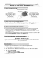
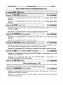
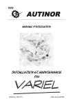
Handlinq advice for eaui~ment:
Whatever the load, handling operations can be dangerous (collision, dropping, crushing,...). Whenever
possible use mechanical handling rather than manual handling. When manual handling can not be avoided, respect
the rules.
At european level, these rules are set out in the Directive 90/269/CEE, Consil Directive dated 19 May 1990
« concerning minimal heath and safety instructions for manual load handling with risks, to the worker, notably in the
lower spiral area N.
Man 18 1 45 years
Man 45 / 60 years
Load permitted
(occasional carrying)
Load permitted
(constant carrying)
30 kg
25 kg
20 kg
25 kg
Safetv measures:
Respect the instructions which were given to you by your hierarchy for the use of
the individual protection equipments (gloves, shoes, glasses ..., anti-falls device).
VECTOR DRIVE
Installation Manual
Page 8
LlMlTS OF USE.
The VECTOR DRIVE controls lift motor whose speed can reach 3 mls.
The Motor must be equipped with a double beam incremental encoder, 500 to 2500
point per turn, output voltage 10V-30V.
The Lift can work with a direct approach provided the controller gives a very accurate
slow down signal.
The VECTOR DRIVE can generate 5 speeds, V2, V I , VO, VINSand Viso.
Maximal Values
Model 2 : ............
20A in415V- 11 HP - 8 kW
Model3:............
30Ain415V-16,5HP-I2kW
Madel 4 :............
40 A in 41 5V - 20 HP - 15 kW
Model 5 : ............
50A in 415V- 27,5 HP - 20 kW
Model 6 : ............
7 0 A in415V-39 HP -28,5 kW
Model 7 :............
90 A in 415V - 50 HP - 37 kW
Model 8 : ............
110Ain415V-61 HP - 4 5 kW
Model 9 : ............
160 A in 415V- 89 HP - 65 kW
w
,
-
IMPORTANT :
The current values shown i n the table take into account the fact that the motor i s
not equiped with a inertia handweel.
All the VECTOR DRIVE are equipped with a 3 phase network current filter, Motor filter,
Regenerative resistors and contactors.
VECTOR DRIVE
Installation Manual
Page 9
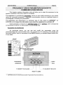
CONTROL OF THE FREQUENCY DRIVE.
For the Frequency Drive to work, it needs as well as a full safety lane, to receive from the
lift controller :
the direction Up or Down, and the movement speed (V2, V I , Vins, Viso or VO),
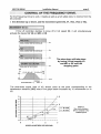
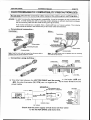
MOVEMENT IN VZ :
If the Lift controller decides to move off in full speed V2, it will simultaneously
activate the Inputs V2, VO and MO or DE.
f
The slow-down will take place
by losing V2 but keeping VO
and MO or DE until the
stopping point.
I
I
mis
f
'
1
VO+V2+MOorDE
I
" 1
I
MO 1
VO+MOorDE! o r ,
ISTOPPING
SLOW DOWN POINT d
POINT-*
I
1
~
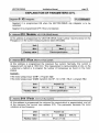
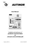
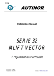
The slow-down signal (loss of V2) should come at the point corresponding to the
deceleration distance (DV2) read in the graph below increased by 10 centimetres run in
vo.
Figure 1
Slow down distance
DV2 in relation to the
nominal speed
SPEED IN METRES PER SECOND
VECTOR DRIVE
Installation Manual
page 10
I
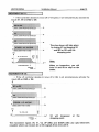
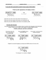
VEMENT IN V I :
* If the controller decides to move off in V I speed, it will simultaneously activate the
Inputs V I , VO and MO or DE.
f
The slow-down will take place
by losing V I but keeping VO
and MO or DE until the
stopping point.
I
~
I
S
t
I
l
1
,
l
VO+VI+MOorDE
I
vO+
I
I
I
I
I
I Moi
,
l
I
I
or,
Note:
-
T
l
I
I
SLOW DOWN POINTSTOPPING
POINT
+:
When on Inspection, you will
lose V I and VO to stop on the
brake.
I
OVEMENT IN VO :
*
If the Lift controller decides to move off in VO, it will simultaneously activate the
inputs VO and MO or DE.
A
7,
1
SIGNAL SENT BY THE V.F. DRIVE
k$
I
1
VO + M O or DE
vo
2
l
STOPPING
POINT1-
i
'
1
.
1
1
Y
I
1
T
VO will disappear
stopping point.
at
the
The movement inputs VO, VI, V2, UP (MO) and DOWN (DE) use opto-electronic
couplers which can receive AC or DC signals from 24 to 220 V.
VECTOR DRIVE
Installation Manual
~aae
11
-
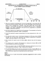
DESCRIPTION OF THE SEQUENCE OF SIGNALS FROM START-UP
IN FULL SPEED V2 UNTlL STOPPING.
A
V2 = high speed
Acceleration
Slow-down
VO = Set-up Speed
and re-levelling
O
1. When the controller has decided that it can use full speed V2, it will activate V2, VO
and give the direction Up (Mo) or Down (De). The VECTOR DRIVE having received the
order to move, energises the L contactor. Then about 200ms later, The S safety
contactor. L and S allow the brake to be energised whilst the rotor is electrically
stabilised. This electric stabilisation will last the time programmed at parameter
« FrDem » (Brake time at start-up).
2. We start by applying low voltage and the lift accelerates. The acceleration will last the
time programmed at parameter « Acce » (Acceleration).
3. The lift has reached the speed corresponding to the value programmed at « V2 » (Full
speed).
4. The slow-down signal is given, the V2 signal disappears but VO stays along with MO
and DE. The car slows down according to the distance programmed at parameter
« DV2 » (Slow-down distance in V2) to reach VO.
5. VO is reached, the signal is given, the VO and MO or DE are kept until the stopping
point.
6. The stopping point is reached, VO disappears but keeping the direction MO and DE
and the transition from VO to zero speed start.
7. When zero speed is reach, the VECTOR DRIVE electrically stabilises the rotor for the
time programmed at parameter « FrArr » (Brake time on stopping).
8. The VECTOR DRIVE drops the brake by deactivating the brake contactor BR (FR). An
L or S contact (STOPR) informs the controller that the movement is finished so that the
MO or DE direction signal can be deactivated and the doors opened.
NOTE :
Stages ( 5 ), ( 6 ), ( 7 ) and ( 8 ) have been voluntarily exaggerated in order to clearly
the drawing.
VECTOR DRIVE
Installation Manual
page 12
INSTALLATION OF THE CONTROL PANEL.
Cabinets dimensions :
Models 2 , 3 , 4 , 5*, 6* : L = 562 mm, H = 680 mm, P = 285 mm, Weight = app 40 Kg
With further cabinets for resistors : L = 320 mm, H =600 mm, P = 250 mm.
Models 7 , 8 and 9 : L = 800 mm, H = 1200 mm, P = 400 mm.
NB:
-
For the purpose of delivery, the support bar is fixed to the studs for fixing the
cabinet.
Entry for wiring and trunking is at the bottom.
Don't forget than the EN-81 part 1 Standard 5 6.3.2.1 (a), amended by
British national variation BS 5655 5 V.3.14 requires that :
6.3.2.1 The dimension of machine room shall be suffïcient to permit easy and safe access for servic
personnel to al1 components, especially the electrical equipment.
In particular there shall be provided :
(a) a clear horizontal area in front of the panels and the cabinet. This area is defined as follows :(N.c)
depth, measured from external surface of the enclosures, at least 0.9 m. This distance may be reduce
0.6 m in front of protruding controls (handles, etc.).
width, the full width of panel or cabinets by 2.14 rn high.
VECTOR DRIVE
Installation Manual
page 13
CONTROLLER POSITION
AND ELECTROMAGNETIC COMPATlBlLlTY (113)
When the machine room supports or is near a radio or television reception
aerial, do not put the controller cabinet in the aerial receiving zone (figure 2).
BAD !
GOOD !
Figure 2 Placing the frequency drive outside the aerial receiving zone
If you can not find a suitable place for the frequency drive cabinet, qet the aerial
moved !. If that is not possible, contact AUTINOR who will decide along with the building
owner, what measures need to be taken according to the EN 12015 and EN 12016
Standard for lifls, escalators and passengers conveyors.
PRECAUTIONS TO TAKE.
1. The power supply arriva1 L I , L2, L3 and Earth (YellowIGreen) must al1 pass through
the same cable.
2. The power link between the VECTOR DRIVE and the motor (11, 12, 13 + Earth) must
go through the same cable. In order to reduce disturbances a screened cable must be
used, even if the motor cable is mechanically protected by a tube or metal trunkway.
This screening should consist of at least one flat cable, the greater the number of flat
cables the greater the efficiency of the screening. The cable should be supple for ease
of installation in the machine room and should comply with EN 81 standards.
To be completely efficient the screening must be connected at the same time to the
controller metal casing and to the motor metal housing.
In order to reduce any coupling effects, it is advisable to maximise the distance
between the motor cable and the three phase power supply cable, both inside and
outside the controller ; for the same reason, you should keep the cables carrying high
current as far apart from those carrying low current as possible. These two types of
cable should not be placed in the same trunkway, nor go through the controller casing
via the same hole.
VECTOR DRIVE
page 14
Installation Manual
ELECTROMAGNETIC COMPATlBlLlTY PRECAUTIONS ( W 3 )
At not time should the screening cable replace the yellow-green earthing cable.
ADVICE : In order to ensure the electromagnetic compatibility, it may be necessary to use to connect to the
rnotor, a rnetal stuffing box with a screening contact allowing an efficient electrical link between
the flat screening cable and the metal housing (see figure below).
If the motor terminal box is isolated, then a metal stuff box is of course useless. The screening
cable should be linked in the shortest way to the rnotor earth terminal block.
Conventional connection :
Yelloy/Green
earthing cable
USlNO A SCREWDRNER
LOWRTHE MOBILE r u r E
10 INSERlTHE SCREENINO CIBLE
lin
Note Keep the motor cable as far apart from the power cable as
Note: The c a b z should only be separated from the
possible, inside as well as outside the controller.
once inside the terminal box.
screening
Connection using stuff-box :
CURVED SEAL
SCREENING
FLAT CABLE
TERMINAL
BOX WALL
3. The other links between the VECTOR DRIVE and the motor, i.e. the brake (+BR and
-BR), the motor thermistor (OV, STH) can run together but kept at least 10 cm from the
power cables.
-
EXAMPLE :
MOTOR SCREENED CABLE
11,12,13 AND EARTH + SCREENING
L i , L2, L3, + EARTH
TRUNKING
ONLY
ARRIVAL BOX
1-L
L I , NEUTRAL
MOTOREISTOR
THERMISTOR,
SHAFT WlRlNG
Check that the power supply arriva1 does not flow close
to the VECTOR DRIVE and motor link.
VECTOR DRIVE
Installation Manual
page 15
USE OF DIFFERENTAL CIRCUIT BREAKERS
WlTH AUTINOR FREQUENCY DRIVES (313)
First of al1 as a reminder :
The low voltage directive explicitly states that electrical lift installations are excluded relating from
its field of application and so the standards relaring to electrical installations only applies as for as
the input terminals of the main lift installation switch (cf EN 81 § 13.1.1.2) ;
nevertheless the safety of al1 people must be ensured, and so to do this, we rely as much as
possible on the detail of C 15-100 taking into account the imperatives concerning lifts.
The standard C 15-100 § 532.2.1.3 states that :
« Les dispositifs de protection à courant différentiel-résiduel doivent être choisis et les circuits
électriques divisés de telle manière que tout courant de fuite à la terre susceptible de circuler durant
le fonctionnement normal des appareils ne puisse provoquer la coupure intempestive du dispositif. D
AUTINOR frequency drives have a normal current leakage of 60 mA when the car is stopped or empty
and around 300 mA when loaded. We therefor recommend the motor be supplied through a differential
circuit breaker with a differential current (= « sensitivity ») IAn= 500 mA.
What is more, C 15-100 states that for electrical installations cabled conform to the TT diagrams
(installations powered by the public electricity network), people should be protected against indirect
contacts by differential residual current circuit breaker which implies the following of the relation ship
which links the circuit breaker differential current IA, to the maximum conventional voltage of the UL
contact and of the earthing socket resistance :
IA, * RA5 UL(NF C 15-100 § 532.2.4.2)
Protection may be ensured by using a differential circuit breaker with a sensibility of 500 mA,
provided the building's earthing socket resistance is maximum 100 R for a lift installation, whose
maximum conventional voltage of the ULcontact is 50 V. It is up to the owner to supply the electrician
with the resistance value of this earthing socket, so that the electrician may ensure that the differential
sensitivity ensures the correct protection against indirect contact.
If the earthing socket resistance exceeds 100 R,the electrician may use an S type differential
circuit breaker with a differential current of 300 mA, which will ensure protection against indirect contact
for an earthing socket resistance of up to 167 a. You should nevertheless ensure that a « full load >>
movement does not break the circuit at the wrong moment.
VECTOR DRIVE
Installation Manual
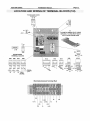
page 16
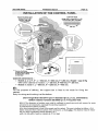
/
FU+
DC PROTECTION
BY PROTISTOR DEPENDING
ON THE DRIVE MODEL.
(SEE TABLE BELOW)
The FU+ position is depending
of the Model
BRAKE CONTACTOR
POWER CONTACTORS
3 PHASES MAIN FILTER
380 V dim: 6 X 32
VECl O
MOTOR CURRENT
MEASURING DEVICE
If you are f o r c e d to change the
VECl O current sensor.
It is ESSENTIAL to c o n n e c t it
to follow an identical wiring path.
/
\
TRANSISTOR
COOLING FAN
PROTECTION
0,5A-250 V dim: 5 X 20 QUlCK ACTING
ATTENTION !!!
\
"
ONLY USE PROTISTORS
CAPABLE OF WHITHSTANDING 600V
AND SPECIALLY CONCEIVED
TO PROTECT SEMICONDUCTORS.
THEUSEOFOTHERFUSES
IS DANGEROUS
AND COULD DAMAGE
THE TRANSISTORS IF THERE IS A POWER
SURGE OR SHORT CIRCUIT !!!
/
VECTOR DRIVE
page 17
Installation Manual
LOCATION AND WlRlNG OF TERMINAL BLOCKS (112).
Towards power supply
transformer
14 POINTS LINKING FLAT CABLE
Between J i on the VECOl board
and J i on the VECOG board
VECOG BOARD
TERMINAL BLOCKS
/
q
vlso
iiMs
1 1 3 0
iio~zzo
1 1 1 kt:,:;;tL,
----L
VO
VI
V2
Toward
ISO Input
(relevelllng)
c
q
c
vlso-
check
Electromechanical Terminal Rail
l
I
12
FuVe
PE
Il
VECTOR DRIVE
Installation Manual
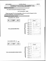
page 19
POWER-UP FOR INITIAL MOVEMENT (112).
1
Switch on the power :
- The LEDs showing the transistors are green.
CUT THE S A F E N LANE
Please see page 21 for the description of how to use the frequency drive
parameterldiagnostic communication device
1
Checking the transistor control :
1) At address 041, write 55
.
. . . . . .. '
..:
&_..:.
RECUP
X2
X1
THE LEDS BECOME RED.
Y2
Y1
22
Zl
2) At address 041, write 00
THE LEDS BECOME GREEN AGAIN.
n i , '.
...
,
..
.
.
.__
..,.
.
:
. . ..: , ...,.....".',.
.
i
',
,
.
...
VECTOR DRIVE
page 20
Installation Manual
-
To check the capacitor voltage :
l
CUT THE S A F E N LANE !
PRESS CONTACTOR
SELECT ADDRESS 104
THE VOLTAGE READ IS ABOUT 600V
MODIF. CLEAR VALID.
MODIF. CLEAR VALID.
0
0
0
-
03-03
b
k the VEClO current measuring device :
c
1
Check at addresses 12A and I2C that the value is between 500 and 524. If the value
are not coherent, check the connection of the K8 connector of the VECOl board.
Ta check the incremental encoder connection :
I
Check at address 116 on the parameterldiagnostic communication device (see page
23) that the number of impulses increases as you turn the rotor in the direction
corresponding to up, and decreases in the direction corresponding to down. Turn the
rotor gently by hand.
If the number of impulses changes in the wrong direction, inverse the CA1 and CBI
wires on the KC22(bottom) connector of the VECOl board.
1check that the parameters are coherent.(see page 37) : 1
RECONNECT THE S A F E N LANE !
Try an up movement and then a down movement, and check that the lift starts off in
the required direction.
(~ossiblefaults :
The system might come up with one or more of the following fault codes :
17 : Phase failure or inversion of the controller.
102 : Gap between the advised and real speed of more than 15% in Slow Speed.
100 : Motor over-intensity.
Cross two of the motor phases.
Check that the encoder is wired correctly.
+
+
62 : 0 0 3 tape head fault.
VECTOR DRIVE
Installation Manual
page 21
FREQUENCY DRIVE PARAMETERIDIAGNOSTIC
COMMUNICATION DEVICE
This chapter contains information which will allow you to adapt the equipment to the
specific conditions of the lift on which it is installed.
This adaptation is controlled by parameters, which you can modify according to your needs
using the removable parameter 1 diagnostic communication device as described below in
the paragraph Accessing the parameters.
The parameters are memorised in a particular type of chip called an EEPROM l (or
E2PROM) which keeps the information even when the equipment is switched off.
Each parameter is linked to an abridsed name and an address which corresponds
to the position at which it is memorised in the EEPROM chip.
ACCESSING
THE PARAMETERS
As mentioned above, you can see and modify the parameters using the
parameterldiagnostic communication tool ; this consists of a 16 character LCD display with
four push buttons, which is connected to the VECOl board by a standard MalelFemale SubD 9 pt cable.
THOUSANDS
UNITS
TENS
TO MODIFY THE VALUES
I
I
l
TO VALIDATE THE DATA
RESET TO ZERO
1
EEPROM stands for Electrically Erasable Programable Read Only Memory.
VECTOR DRIVE
Installation Manual
page 22
To aécess the parameters and the input-output information
Power-up the equipment, the display shows :
Each time you press 1 the value shown will increase by 1.
Each time you press 10 the value shown will increase by 10.
Each time you press 100 the value shown will increase by 100.
Choosinq the lanquaqe
The parameterldiagnostic communication device is preset to the language of the destination
country. There are four options which appear at address 027 as follows :
FRANCE, ENGLISH, DEUTSCH, ESPAGNOL.
Press twice button 10,
then 7 times button 1,
for address 027
Press both MODlF buttons
at the same time
Press button 1 and choose the
required language.
--
MODIF. CLEAR VALID.
MODIF. CLEAR VALID.
r
-
MODIF.,CLEAR,
VALID.
Register the required language by pressing both VALID buttons at the same time
r - 027
Cauntry ENGLISH
1000
100
10
1
MODIF. CLEAR VALID.
The language in our example is English
VECTOR DRIVE
Installation Manual
~ a a 23
e
Other example :
Viewinq the incremental encoder impulses (see paae 20).
Reset the display to address 000
by pressing the CLEAR buttons
simultaneously
Display address 116 using
buttons 100, 10 and 1
\
J
\
1000
100
10
1
1000
100
10
1
(-j-ë,-Q-o
MODIF. CLEAR VALID.
MODIF. CLEAR VALID.
.:wy
l x
The value displayed at address
116
increases when the rotor turns
in the upwards direction
1000
100
10
l x
6x
The value displayed at address
116
decreases when the rotor turns
in the downwards direction
1
1000
MODIF. CLEAR VALID.
100
10
1
MODIF. CLEAR VALID.
Transfer of the settinas included in the V W F toward the diaanostic tool.
Press the 2 end buttons to make
« READ PARAMETERS >>
appear.
Press the 2 end buttons
to return to normal mode
Validate by pressing the
« VALlD » buttons
..... Transfert
-
. -
vo
READ Adr.
-MODIF. CLEAR VALID.
MODIF. CLEAR VALID.
-
0,150rnls
..... ..
MODIF. CLEAR VALID.
Transfer of the settinqs included in the diaanostic tool toward the VVVF.
Press the 2 end buttons,
you read,
« READ PARAMETERS ))
,
- ---
7
7
--
--
Display
« WRlTE PARAMETERS )>
using button 1
-
-
MODIF. CLEAR VALID.
-.
-
-
r
\
1
READ PARAMETERS
C=7-7-
-
Press the 2 end buttons to
return to normal mode
Validate by pressing the
« VALID » button
..... Transfert
.
1
WRITE PARAMETERI
-- MODIF. CLEAR VALID.
-
-
-
1 000
F8xx
-
-
VO
0,lSOmls
-
\
MODIF. CLEAR VALID.
MODIF. CLEAR VALID.
To remind vourself of the address.
If you forget the address you are changing, or the previous value
shown, just press both MODIF buttons.
1/
1
7
004
1
1000
100
10
MODIF. CLEAR VALID.
r--
1
VECTOR DRIVE
Installation Manual
page 24
To chanqe the parameters in decimal mode
After selecting the required language (see previous page) you can access the parameters and
change them if required.
Reset the display by pressing
both CLEAR buttons
at the same time
1000
100
10
To change the V2 speed for
example, display address 004
by pressing button 1
Press both
MODlF buttons
at the same time
MODIF. CLEAR VALID.
MODIF. CLEAR VALID.
1
MODIF. CLEAR VALID.
Register the new speed by
pressing both VALlD buttons at
the same time
Press button 10 5 times to obtain
the desired speed
--MODIF. CLEAR VALID.
MODIF. CLEAR VALID.
To chanqe the parameters in seqment mode
You can access the options using segments and change them if so desired.
SegO : IG, Segl : NOBAND, Seg2 : BATTERY, Seg3 : MLI,
Seg4 : RETSEC, Seg5 :APPDIR, Seg6 : D65", Seg7 : ML220V
Reset the display by pressing
both CLEAR buttons
at the same time
Display address OOE
by pressing button 1
Press both MODlF buttons
at the same time
MODIF. CLEAR VALID.
MODIF. CLEAR VALID.
MODIF. CLEAR VALID.
11 x
Press button 10
to obtain the required segment
example : Direct approach.
Press button 1
to activate segment 5.
Register the new data in the
memory by pressing both VALlD
buttons at the same time.
- - - - - -1
I
MODIF. CLEAR VALID.
0
-
MODIF. CLEAR VALID.
I
d
i/
\
BtS
MDF
-
-
. --.
AP-DIR 1
-
MODIF. CLEAR VALID.
W'
VECTOR DRIVE
Installation Manual
page 25
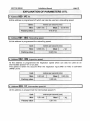
EXPLANATION OF PARAMETERS (117).
Address 000 : VO, VO.
At this address is programmed VO which can also be used as a relevelling speed.
Units :
Mini :
mettes per second (mls)
0,001 mls
,-
1/10 of V2
Factory value :
L
Address 001 : [Su,Relevelling speed.
At this address is programmed the relevelling speed.
Address 002 : INS, Inspection speed.
.
At this address is programmed the Inspection speed which can also be used as an
intermediate speed if V I is not used.
This speed is taken into account when the inspection input (INSI on K30) is activated
(VINS Led lit).
Unit :
Mini :
mettes pet- second (mfs)
0,20 mls
Factory value :
M
i:
0,60 m[s
0,50 mls
Address 003 : V I , Intermediate speed V I .
At this address is programmed the Intermediate speed V I .
Unit :
Mini :
Factory value :
metres per second (mls)
0,61 mls
Maxi :
0,61 mls
< V2
VECTOR DRIVE
Installation Manual
page 26
EXPLANATION OF PARAMETERS (217).
* Address 004 : V2, Fut1 speed V2.
At this address is programmed the Full speed.
metres per second (mls)
Unit :
Mini :
Maxi :
>VI
Clients specification
Factory value :
i
04,OQ m/s
c
Address
006 : VSY,Synchronous speed.
At this address is programmed the movement speed of the car when the motor turns at its
synchronous speed.
1500 t/min for a 4 pole motor
Unit :
Mini:
1000 t/min for a 6 pole motor
metres per second (mls)
Maxi :
O,000rn/s
Factory value :
9,999 m/s
Spécificité client
Formula :
Calculation of the synchronous speed for a 1500 tlmin motor :
vsy,
E x n d
60
Reductor ration x roping
n: = 3,14 - d = diameter of the pulley - Roping = 1 or 2 or 4
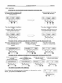
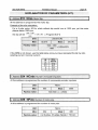
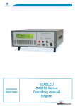
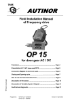
Address 008 : DV2, Slow-down distance on V2.
At this address is programmed the slow-down distance necessary when in full speed V2.
Unit :
metre (m)
-,
Mini :
Factory value :
0,000 m
Maxi :
9,999 m
Clients specification
Figure 3
Slow-down distance
value (DV2) in fact of
the full speed (V2)
O
0.5
1
1.5
2
2.5
VITESSES EN METRE PAR SECONDE
3
VECTOR DRIVE
Installation Manual
page 27
EXPLANATION OF PARAMETERS (317).
Address OUA : Acce, Acceleration.
At this address is programmed the time to reach V2 speed.
Unit :
Mini :
second (s)
02,O s
Maxi :
Factory value :
25,5 s
03,Os
Address 00 B : FrArr, Brake time on stopping.
At this address is programmed the time to stabilise the rotor before the brake is dropped.
second (s)
Unit :
Mini :
0,30s
Maxi :
0,80s
0,5 s
Factory value :
Address OOC : FrDern, Brake time on start-up.
At this address is programmed the time during which the rotor is stabilised to allow the
brake to lift correctly before start-up.
Unit :
Mini :
second (s)
0,OOs
Maxi :
0,60 s
+
Factary value
Address
Q,5s
;
OOD : Thermi, Motor thermistor.
At this address is programmed the current at which the electronic thermical relay is
activated. (since programme V02)
Ampere (A)
Unit :
Mini :
Factory value :
....... A
Maxi :
....... A
Spécificité client
The thermal relay switches switch off if ,the motor intensity (Imot) is higher than the
thermal intensity (Ith) for longer than 3,5 seconds or if the motor intensity (Imot) is 1,5 A
higher than the termal intensity (Ith).
lmot can be seen at the address 108, page 35.
VECTOR DRIVE
Installation Manual
page 28
EXPLANATION OF PARAMETERS (417).
Addresç
OOE : Opt, Option.
Segment 7 : ML220V, M L I 2
~ 2~0 ~ .
[(ooEoptlOMMOOO3]
Segment 7 is programmed ON when the Vector drive is on a three phase 220V
network.
Segment 7 is programmed OFF when the Vector drive is on a three phase 400V
network.
-
--
[segment
6 : D65O, Fault T0>65".
(-E
-0 0 ~
OP~OI0
..
Segment 6 is programmed ON to increase the radiator temperature detection threshold
from 60°C to 65°C.
Segment 6 is programmed OFF to keep the detection threshold at 60°C.
[segment
5 : APPDIR, Direct Approach.
Segment 5 is programmed ON to remove VO so that the car can level with direct
approach.
1
Segment 5 is programmed OFF if this is not desired.
Segment 4 : RETSEC, Deiay on çafety contactor.
Segment 4 is programmed ON to filter the rebound of the S contactor contacts on startup, and when these contacts are used to cut the motor power supply.
Segment 4 is programmed OFF when the S contacts are not used to control the motor.
I ~ e ~ m e3n :t ML!, V.F. + n NON AUTINOR a Controller.
1
Segment 3 is programmed ON when the VECTOR DRIVE is associated to an other
controller than AUTINOR.
1
Segment 3 is programmed OFF when the VECTOR DRIVE is associated to an
AUTINOR controller using the slotted tape.
segment
2 : BATERI,Battery.
Option available later in 1999
Segment 2 is programmed ON to activate the emergency return to floor level using battery
po wer supply. This option requires an extra ,emergency po wer supply.
lsegrnent
1 : N O B A N D , NU
slotted tape.
Segment 1 is programmed ON when there is no tape or 003 tape-head. In this case, a
high speed tachometer is required.
Segment 1 is programmed OFF when the speed information cames from the slotted
tape and 0 0 3 tape-head.
VECTOR DRIVE
Installation Manual
page 29
EXPLANATION OF PARAMETERS (517).
1
Segment O : IG, Integrator.
Segment O is programmed ON when the VECTOR DRIVE slip integrator is to be
activated.
Segment O is programmed OFF if this is not desired .
*
A d d ~ s sO f O : Modefe,VECTOR DRIVE Mod~tl.
At this address is programmed the VECTOR DRIVE model number. See the sticker on the
Plexiglas or on the current measuring device label (VEC02M).
Unit :
None
W .
Mini :
2
Factory value :
Maxi ;
9
Clients specification
-
P
.
Address 03 2 : ~ F ~ uMaximum
x,
flux curient.
At this address is programmed the maximum flux current. Normally, this current is
measured with no load at 1500 tr/mn. This measurement is rarely possible on site, so the
« empirical » method is to program the number of horsepower as found on the motor
plaque.
Example :
=
If the motor plaque says 12 HP Program 12,O
If the motor plaque says 12 kW, transform into HP, 12 / 0,736 = 16,3 3 program 16,3
Ampere (a)
Unit :
Mini:
000,IA
Factary value :
Clients specification
Address 014 : I F m i n , minimum flux current.
At this address is programmed the minimum flux current,which is approximately one half
of the maximum flux current (see address 012). This parameter decreses the motor
vibrations at low frequency.
Ampere (a)
Unit :
Mini :
Factory value :
000,l A
Maxi :
IFlux 1 2 = (A)
999,9 a
Installation Manudl
VECTOR DRIVE
page 30
EXPLANATION OF PARAMETERS (617).
Address 016 : Gliss, Motor Slip.
At this address is programmed the motor slip.
Examrsle of the slip calculation :
For a 4 pole motor, 50 Hz, which without slip would turn at 1500 rpm, yet the motor
plaque states 1380 rpm,
the slip will be
1500 - 1380
=
o,o8 ie 8% 3 Program 08,O
%
1 500
If the RPM is not shown, use the table below once you have calculated the Id / I n ratio
(starting current / nominal current)
I
Address 024 : NCode, Number of encoder impulses.
At this
Address 026 : NPole, Number of mdor pole.
At this address is programmed the number of motor pole.
None
Unit :
Mini :
Factory value :
004
Maxi :
006
4 or 6 pôles, if 6 pôles, Ncode = 750 min
VECTOR DRIVE
Installation Manual
page 31
EXPLANATION OF PARAMETERS (717).
Address 027 : Colîntry, Language.
" " '
At this address can be programmed the language to be used on the VEC03 programming
tool.
Possible choice :
France, English, Deutsch *, Espatïol
* In Germany, the Inspection speed can go up to 0,80 mls and the levelling speed up to
0,50 mls.
Address
034 : Dem, Number of starts. . =>
OOOOx xxx
At this address, can be read the number of starts carried out by the lift and the 4 strong
weight bits can be modified.
..
Adresse 036 : Dem, Number of starts. => x x x x O O O O
At this address, can be read the number of starts carried out by the lift and the 4 light
weight bits can be modified.
r Addreçs
041 : Test, Transistor test.
At this address, can be written 55 to check the transistors.
All of the LEDs turn red if al1 of the transistors are working properly.
h
Adresse 042 : Prog, Type of Programme.
At this address, the selected programme can be read.
VEC (VECtoriel) Vector, SCA (SCAlaire), ARB (ARBre lent) Gear Less.
Adresse 043 : TMan, Type of Controiier.
At this address, the type of controller associed with the VECTOR DRIVE can be read.
Normal (AUTINOR Controller or with a VECOG interface board),
1Vit (1 speed controller), 2Vit (2 speed controller)
Adresse 044 : Mcode, Memorisation of a personal code number.
At this address can be memorised a personal code number to program against al1 chance
intervention. The equipment set with the factory code 0000 allowing complete and
permanent access to the set of settings.
After programming your code (Don't forget to take note of it), the address 044
dissappears. If you want to modify the settings, enter your Code at the address 046.
Adresse 046 : Code, Access Code.
At this address, enter your Code to unlock the address 044 in order to modify the setting
andior change the memorised code.
I
VECTOR DRIVE
Installation Manual
page 32
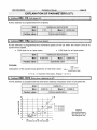
EXPLANATION OF INPUTS (112)
L
~ d d t e s s1O0 : En1, inputs O to 7.
[segment 7 : NOT USED.
1
Segment 6 : V2, Speed V2. (Full speed)
[
&
l
a
]
lndicates the State of the input for speed V2.
Segment 6 lights up when the lift is required to move at speed V2.
Segment 6 is not lit otherwise.
[segment 5 : V I , Speed V I . (Intermediate speed)
lndicates the State of the input for speed V I .
Segment 5 lights up when the lift is required to move at speed V I .
Segment 5 is not lit otherwise.
Segment 4 : Vu, Speed VO.
lndicates the State of the input for speed VO.
Segment 4 lights up when the lift is required to move at speed VO.
Segment 4 is not lit otherwise.
Segment 3 : INS, inspection speed.
lndicates the State of the inspection input.
Segment 3 lights up when the lift is required to move on inspection.
Segment 3 is not lit otherwise.
kegment
2 : VISO, Relevelling speed.
lndicates the State of the relevelling input. (VISO+ & VISO-)
Segment 2 lights up when the lift is required to relevel.
Segment 2 is not lit otherwise.
lsegment
1 : DE, Down.
lndicates the State of the Down input.
Segment 1 lights up when the lift is required to go down.
Segment 1 is not lit otherwise.
[ G
-T ~
A
VECTOR DRIVE
Installation Manual
page 33
EXPLANATION OF INPUTS (212)
[segment
O : MO, p.
lndicates the State of the Up input.
Segment O lights up when the lift is required to go up.
Segment O is not lit otherwise.
-
1
Addresç 102 : En2, inputs O to 7.
segment
7 : NOT USED.
egment 6 : NQT USED.
1
Segment 5 :CCL, L Contactor Check.
Indicates the State of the Line Contactor.
Segment 5 lights up when the Line contactor is de-energised.
Segment 5 it is not lit when the Line contactor is energised.
b m e n t 4 : CCS, S Contactor Check.
lndicates the State of the Safety Contactor.
Segment 4 lights up when the Safety contactor is de-energised.
Segment 4 it is not lit when the Safety contactor is energised.
Segment 3 : NOT USED.
Isegment 2 : NOT USED.
Segment 1 :CAA. Tape-head 003 - Beam A.
lndicates the State of the Beam A (Top Beam) on the 0 0 3 tape-head.
Segment 1 lights up when the Beam A is cut.
Segment 1 is not lit otherwise.
Segment 0 : CAB, Tape-head 003 - Beam B.
Indicates the State of the Beam B (Bottom Beam) on the 0 0 3 tape-head.
Segment O lights up when the Beam 6 is cut.
Segment O is not lit otherwise.
VECTOR DRIVE
Installation Manual
page 34
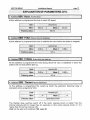
EXPLANATION OF OUTPUTS.
Address
1
1
101 : S O ~Outputs
,
O to 7.
Segment 7 : NOT USED.
Ili
Segment 6 : FR, Brake reiay.
~ . s ~ I ~ ~ O O ]
01 sor
- .- 1OOOQOOO]
.
lndicates the State of the Brake relay output (BR).
Segment 6 lights up when the brake relay output is activated.
Segment 6 is not lit otherwise.
Segment 5 : NOT USED.
1
segment 4 : DEF. ~ a uRelay.
~t
lndicates the State of the Fault relay output (DEF on V E C O G board).
Segment 4 lights up when the fault relay output is activated.
Segment 4 is not lit otherwise.
[segment
3 : RISO, Relevelling Fault Relay.
lndicates the State of the relevelling fault relay output (RIS0 on V E C O G board).
Segment 3 lights up when the relevelling fault relay output is activated.
Segment 3 is not lit otherwise.
Segment 2 : VENT, Fan reiay.
lndicates the State of the Fan relay output. (VENT).
Segment 2 lights up when the fan relay output is activated.
Segment 2 is not lit otherwise.
1
Segment I : S, Safety reiay.
lndicates the State of the Safety relay output (S).
Segment 1 lights up when the safety relay output is activated.
Segment 1 is not lit otherwise.
[segment O : L. Line relay.
lndicates the State of the Line relay output(L).
Segment O lights up when the line relay output is activated.
Segment O is not lit otherwise.
J
VECTOR DRIVE
Installation Manual
page 35
EXPLANATION OF VARIABLES (112)
Address
103 : TO,Radiator Temperature
in degrees Celsius
(O)
At this address can be read the power transistors cooling radiator temperature.
4
Address
104 : TCont, Capacitor Current
in Volts (il)
F
At this address can be read the D.C. net capacitor terminal current.
Address
1O8 : lm0t Motor Current
in Amps (A)
At this address can be read the current in each phase of the motor
Address
10A : DVO.VO çtopping distance
in metres (m)
At this address can be read the distance necessary to smooth VO into zero speed.
Address
lm : Disu, Relevellingstopping distance
in metres (m)
At this address can be read the distance necessary to smooth VISO into zero
speed.
Address 1OC : Dlns, inspection slow-down distance
in metres (m)
At this address can be read the slow-down distance associated with the inspection
speed VINS.
4
Address 10E : DVl, V I slow-down distance
in metres (m)
At this address can be read the slow-down distance associated with the
intermediate speed V I .
Address
11O : Fre, Frequency sent to the motor
in Hertz (Hz)
At this address can be read the instantaneous frequency applied to the motor.
Address
1t 2 : Con, reference
in Hertz (Hz)
At this address can be read the referencelldeal frequency to be followed.
VECTOR DRIVE
Address
page 36
Installation Manual
114 : Vf, Lift speed
in metres pet- second (mis)
At this address can be read the car speed.
At this address can be read the counting of the incremental encoder mounted on the
motor.
Address 118 : Recup, Energy regeneration
in percent (%)
At this address can be read the percentage of energy consumed in the x
regenerative resistors. ( x = number of regenerative resistors depending of the drive model)
Address
7 A : T m t , motor power supply current
in percent (%)
At this address can be read the power current applied to the motor.
L
Address $20 : GD, Deceleration Gradient in V2 speed in metre per second squafed (m/s2]
At this address can be read the deceleration slope associated with the different
speed.
L
r Address
4 22 : DRal, Slow-down distance
in metre (m)
_I
At this address can be read the slow-down distance still to run.
Address
12A : 1 Capl, Current measuring device 1
no Unit
At this address can be read the information given by the current measuring device 1
Note : At Stop the information should be between 500 and 524.
Address 12C :
Capz, Current measuring device 2
no Unit
At this address can be read the information given by the current measuring device 2.
Note : At Stop the information should be between 500 and 524.
T ~ d d r e s s12E : 1
Capa, Current measuring device 3
no Unit
At this address can be read the information given by the current measuring device 3
Note : At Stop the information should be between 500 and 524.
VECTOR DRIVE
page 37
Installation Manual
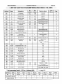
LIST OF VECTOR PARAMETERS AND FINAL VALUES.
Finals
Values
Address
Name
Designation
Min
values
Max
values
Factory values
O00
VO
Set-up speed
0,001
0,199
1/10 de V2
25
25
Page
001
Iso
Re-levelling speed
0,0oO
< VO
0,020 m/s
002
Ins
Inspection speed
0,20
0,60
0,50 m/s
25
003
VI
lntermediary speed
0,61
< V2
0,61 mls
25
004
V2
Full speed
> VI
03,00
Clients pecificaüun (mis)
26
006
VSY
Synchronous speed
0,000
9,999
Clients speufication (m/s)
26
008
DV2
V2 Slow down distance
0 , m
9,999
Chénts specification (m)
26
O0A
Acce
Acceleration
02,O
25,5
3,O s
27
OOB
FrArr
Brake stopping time
0,30
0,80
0,5 s
27
OOC
FrDem
Brake starting time
0,OO
0,60
0,5 s
27
OOD
Thermi
Motor thermistor (A)
Cknts specification (A)
27
OOE
OPt
Hardware option
Clients specificaüun (rnls)
28
OOF
RgT0
Temperature Sonde Calibration
4 "c
O10
Model
Vector model
011
Tmor
Transistor pause time
012
IFlux
Flux current max
000,l
999,9
Number of horse power (A)
29
014
IFmin
Flux current min
000,l
999,9
lFlux12 = (A)
29
016
Gliss
Motor slip
02,O
20,O
018
Jreg
lnertia
005 %
019
GP max
Max Proportional Gain > 12 Hz
O15
01A
GP min
Min Proportional Gain c 12 Hz
004
OIB
GI max
Max integral Gain
O1O
01C
GI min
Min integral Gain
001
OlD
G Deri
Derived Gain
000
OIE
GI Dep
Start up integral Gain
005
OlF
GP Dep
Start up Proportional Gain
005
020
T Dema
Start up Voltage
006 %
021
G Stabi
Stabilisation Gain
O15
022
FTmax
Max Voltage Frequency
050 Hz
023
FMinD
Min Starting Frequency
0,10 Hz
024
NCode
No Encoder Teeth
0500
2500
500 (500 < x < 2500)
30
026
NPole
No of motor Poles
004
006
4 or 6 pdles
(if 6 pgles, NCode=750mini)
30
027
Country
Country Language
2
29
Ciieots specifceifon
9
1 3 Cis
1500 - RPM
30
XI00 = %
1500
a,@,-,@ 31
-
>\Il/,
* Opt parameter Detail OPTion - Address OOE : =,Q-a page 28.
Address
Name
Seg 7
Seg 6
Seg 5
Seg 4
Seg 3
Seg 2
Seg 1
Seg O
OOE
OPt
ML220V
D65"
APPDIR
RETSEC
ML1
BATERI
NOBAND
IG
O
O
O
O
1
O
1
O
FACTORY VALUE
FINAL VALUE
VECTOR DRIVE
~ a a 38
e
Installation Manual
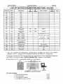
LIST OF VECTOR PARAMETERS AND FINAL VALUES
1
1
1
1
1
02F
1
PileDef
1
1
Fault 8
1
030
PileDef
Fault 9
031
PileDef
Fault 10
034
Dem
Number of starts
(Full load)
O000
9999
OOOOxxxx
036
Dem
Number of starts
(EmPtY)
O000
9999
xxxxOO00
038
Visu1 '
VISU no 1 Address
PROGRAMMATION
039
Visu2 '
VISU no2 Address
OF THE CURVES
03A
1
Visu3'
1
VISU no3 Address
038
Visu4 '
VISU no4 Address
040
HinTen
Disable of voltage control
04'
042
l
1
Test
Prog
I
1
Transistor Test
(Program 55 for test)
Programme Type
1
1
1
I
1
1
1
VEC,SCA,ARB
Normal, 1 speed, 2 speed
044
Mcode
Code no memory
O000
1
Code no entry
I
00
Controller Type
Code
1
ON COMPUTER
TMan
1
1
VlSUALlSED
043
046
1
(
1
* You can visualise the parameters, inputsloutputs, variables as well as the function
graphs on a P.C., using the P313 interface board and the VlSU P.C. programme.
To do this, connect the P313 set and push the 2 end buttons of the intergrated diagnostic
tool VEC03. In order to make « READ PARAMETERS » appear on the display.
At the end on the P.C. visualisation, push the 2 end buttons.
If F e diagnostic tool is integrated in the
,
it is E,SSENTIAL to press the 2 end b - o y
SOFTWARE
WSUPC (LOCAL)
You can visualise :
The theoretical graph : .............................................
The real graph : .........................................................
The capacitor voltage :...............................................
The efficient motor current : .......................................
F912
F91O
F904
F908
VECTOR DRIVE
Installation Manual
page 39
LIST OF VECTOR INPUTSIOUTPUTS
Address
Name
Seg 7
Seg 5
Seg 6
Seg 4
Seg 3
Seg 2
Seg 1
Seg O
Page
VISO
DE
MO
32
VENT
S
L
34
CAB
33
Inputs 1
100
V2
En1
VO
VI
INS
Outputs
101
FR
Sor
I
RIS0
DEF
1
CCL
1
Inputs 2
CCS
1
I
1
CAA
1
102
En2
103
TO
Radiator Temperature ("C)
35
104
TCond
Capacitor voltage (v)
35
108
lmot
Motor lntensity (A)
35
10A
DVO
VO Stopping distance (m)
35
1OB
Diso
ISO Relevelling Stopping distance (m)
35
1OC
Dlns
Slow down distance in inspection speed (m)
35
10E
DV1
Slow down distance in speed V I (m)
35
110
Fre
Frequency serf by the motor (Hz)
35
112
Con
Theoretical 1 reference (Hz)
35
114
Vt
Liff Speed (mis)
36
116
Codeur
lncremental encoder
36
118
Recup
Energy recovery (%)
36
11A
TMot
Motor power voltage (%)
36
120
GD
V2 Speed slow down gradient (mis2)
36
122
DRal
Slow down distance (m)
36
12A
lCapl
lntensity measurement device 1
36
12C
I Cap2
lntensity measurement device 2
36
12E
I Cap3
lntensity measurement device 3
36
VECTOR DRIVE
Installation Manual
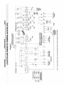
page 40
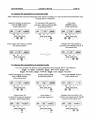
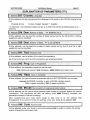
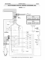
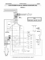
ELECTROMECHANICAL WlRlNG DIAGRAMS (114)
MODEL 2
PHASE FAlL CONTROL
EARTH CONNECTION
iWTH A MET& SPACER
POWER SUPPLY
=> See location and wiring of terminal blocks, page 17.
VECTOR DRIVE
Installation Manual
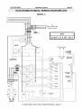
ELECTROMECHANICAL WlRlNG DIAGRAMS (214)
-
MODEL 3 4
=> See location and wiring of terminal blocks, page 17
page 41
VECTOR DRIVE
Installation Manual
page 42
ELECTROMECHANICAL WlRlNG DIAGRAMS (314)
MODEL 5
TO.
SUPPLY TRANSFORMER
PHASE FAlL CONTROL
=> See location and wiring of terminal blocks, page 17.
VECTOR DRIVE
Installation Manual
page 43
ELECTROMECHANICAL WlRlNG DIAGRAMS (414)
MODEL 6
PHASE FAlL CONTROL
ELECTRONIC SUPPLY
OV
18V
TEMPERATURE
W H A M E T U SPACER
BRJKE
1
P O W R SUPPLY
=> See location and wiring of terminal blocks, page 17.
VECTOR DRIVE
Installation Manual
page 44
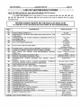
LIST OF VECTOR FAULT CODES
FAULTS DISPLAYED BY THE VECTOR DRIVE (VECOI Board)
The VECTOR DRIVE fault code stack is found at Address 28, 29, 2A, 2B, 28, 2C,
2D, 2E, 2F, 30 and 31. At Address 28 the most recent fault and at Address 31 the oldest
recorded fault.
BEFORE LEAVING THE SITE, SET THE FAULT LIST BACK TO 00.
IN THIS WAY YOU CAN KEEP BETTER TRACK OF ANY BREAKDOWNS.
FAULT
No
DESlGNATlON
VISUALISATION
-00-10-
No fault
Phase inversion
-2252-
FUNCTlONlNG CORRECTLY.
INVERSION IN THE ROTATION DIRECTION (DETECTED BY THE
TAPE HEAD)
CONSÉQUENCE OF AAND B SIGNALS CHANGING STATE AT
THE SAME TlME
SLIP INTEGRATOR.
« 10 » CUT WHlLE IN MOTION.
-62-
FAULT WlTH THE 003 TAPE HEAD.
-80-81-82-
POWER SUPPLY CAPACITOR (tc) MlSSlNG AT START-UP.
AVERAGE CURRENT HIGHER THAN ALLOWED CURRENT.
REAL SPEED 15% HIGHER THAN PROGRAMMED NOMINAL
SPEED Vn.
INSPECTION SPEED EXCEEDS 0,6 MIS.
RELEVELLING SPEED EXCEEDS 0,3 MIS.
-11-
-83-84-
Tape head
fault
lntegrator
10 cut while
in motion
Tape head
counling irrational
Current < 450 v at start-up
Thermistor
Speed > 115% of la nominal
speed
Inspection speed > 0.6 mls
Relevelling speed > 0.3 mls