1
INSTALLATION MANUAL
Outdoor unit for air to water heat pump
ERYQ005ABV3
ERYQ006ABV3
ERYQ007ABV3
ERYQ005ABV3
ERYQ006ABV3
ERYQ007ABV3
Outdoor unit for air to water heat pump
CONTENTS
Page
■
Safety precautions............................................................................. 1
Accessories....................................................................................... 2
Installation manual
After completing installation, test the unit to check for installation
errors. Give the user adequate instructions concerning the use
and cleaning of the unit as included in the operation manual of
the indoor unit.
Installation guidelines........................................................................ 2
Precautions for selecting the location ........................................................ 2
Selecting a location in cold climates .......................................................... 2
Refrigerant piping specifications................................................................ 3
Installing near a wall or obstacle................................................................ 3
Outdoor unit installation drawing ............................................................... 3
Warnings
■
Installation should be left to the dealer or another professional.
Improper installation may cause water leakage, electrical shock,
or fire.
Mounting the outdoor unit .......................................................................... 4
Drain work.................................................................................................. 4
Flaring the pipe end ................................................................................... 4
Connecting the refrigerant piping to the outdoor unit ................................ 4
Refrigerant piping work.............................................................................. 5
Purging air and checking gas leakage....................................................... 5
Charging refrigerant................................................................................... 6
Wiring ........................................................................................................ 6
■
Install the outdoor unit according to the instructions given in this
manual.
Incomplete installation may cause water leakage, electrical
shock, or fire.
■
Be sure to use the supplied or specified installation parts.
Use of other parts may cause the unit to vibrate loose, and may
cause water leakage, electrical shock, or fire.
Test run and final check .................................................................... 8
■
Install the outdoor unit on a solid base that can support the
weight of the unit.
An inadequate base or incomplete installation may cause injury
in the event the unit falls off the base.
■
Electrical work must be carried out in accordance with the
installation manual and the national electrical wiring rules or
code of practice.
Insufficient capacity or incomplete electrical work may cause
electrical shock or fire.
■
Be sure to use a dedicated power circuit. Never use a power
circuit shared by another appliance.
■
For wiring, use a cable long enough to cover the entire distance
with no connection. Do not use an extension cord. Do not put
other loads on the power supply, use a dedicated power circuit.
Failure to do so may cause abnormal heat, electric shock, or fire.
■
Use the specified types of wires for electrical connections
between the indoor and outdoor unit.
Firmly clamp the interconnecting wires so that their terminals
receive no external stress. Incomplete connections or clamping
may cause terminal overheating or fire.
■
After connecting the interconnecting and supply wiring, be sure
to shape the cables so that they do not put undue force on the
electrical covers or panels.
Install covers over the wires. Incomplete cover installation may
cause terminal overheating, electrical shock, or fire.
■
If any refrigerant has leaked out during the installation
work, ventilate the room.
The refrigerant produces a toxic gas if exposed to
flames.
■
After all installation is complete, check to make sure
that no refrigerant is leaking.
The refrigerant produces a toxic gas if exposed to
flames.
■
When installing or relocating the system, be sure to keep the
refrigerant circuit free from substances other than the specified
refrigerant (R410A), such as air.
Any presence of air or other foreign substance in the refrigerant
circuit causes an abnormal pressure rise or rupture, resulting in
injury.
■
During pump down operation, stop the compressor before
removing the refrigerant piping.
If the compressor is still running and the stop valve is open
during pump-down, air will be sucked in when the refrigerant
piping is removed, causing abnormal pressure in the freezer
cycle which will lead to breakage and even to injury.
Installation procedure........................................................................ 4
Trial operation and testing.......................................................................... 8
Items to check............................................................................................ 8
Pump down operation ....................................................................... 8
Pump down procedure............................................................................... 8
Forced cooling operation ........................................................................... 8
Disposal requirements ...................................................................... 8
READ THESE INSTRUCTIONS CAREFULLY BEFORE
INSTALLATION. KEEP THIS MANUAL IN A HANDY
PLACE FOR FUTURE REFERENCE.
IMPROPER INSTALLATION OR ATTACHMENT OF
EQUIPMENT OR ACCESSORIES COULD RESULT IN
ELECTRIC SHOCK, SHORT-CIRCUIT, LEAKS, FIRE OR
OTHER DAMAGE TO THE EQUIPMENT. BE SURE ONLY
TO USE ACCESSORIES MADE BY DAIKIN WHICH ARE
SPECIFICALLY DESIGNED FOR USE WITH THE
EQUIPMENT AND HAVE THEM INSTALLED BY A
PROFESSIONAL.
IF UNSURE OF INSTALLATION PROCEDURES OR USE,
ALWAYS CONTACT YOUR DAIKIN DEALER FOR
ADVICE AND INFORMATION.
SAFETY
■
PRECAUTIONS
This manual classifies the precautions into WARNING and
CAUTION. Be sure to follow all the precautions below: they are
all important for ensuring safety.
Failure to follow any of WARNING is likely to result in such
grave consequences as death or serious injury.
Failure to follow any of CAUTION may in some cases result
in grave consequences.
■
The following safety symbols are used throughout this manual.
Be sure to observe this instruction.
Be sure to establish an earth connection.
Never attempt.
Installation manual
1
ERYQ005~007ABV3
Outdoor unit for air to water heat pump
3P177782-1B
■
■
■
During installation, attach the refrigerant piping securely before
running the compressor.
If the compressor is not attached and the stop valve is open
during pump-down, air will be sucked in when the compressor is
running, causing abnormal pressure in the freezer cycle which
will lead to breakage and even to injury.
■
■
GUIDELINES
Precautions for selecting the location
Be sure to establish an earth. Do not earth the unit to a
utility pipe, surge absorber, or telephone earth.
Incomplete earth may cause electrical shock. A high
surge current from lightning or other sources may
cause damage to the outdoor unit.
WARNING
Be sure to install an earth leakage circuit breaker.
Failure to do so may cause electrical shock.
Cautions
■
INSTALLATION
Do not install the outdoor unit in a place where there is
danger of exposure to inflammable gas leakage.
If the gas leaks and builds up around the unit, it may
catch fire.
Note for installing the outdoor unit.
In cold areas where the outside air temperature remains below
or around the freezing-point for a few days, the outdoor unit's
drain may freeze. If so, it is recommended to install a heater tape
in order to protect drain from freezing.
Tighten the flare nut according to the specified method such as
with a torque wrench.
If the flare nut is tightened too hard, the flare nut may crack after
a long time and cause refrigerant leakage.
Installation manual
1
■
Small animals making contact with electrical parts can
cause malfunctions, smoke or fire. Please instruct the
customer to keep the area around the unit clean.
Choose a place solid enough to bear the weight and vibration of
the unit, where the operation noise will not be amplified.
■
Choose a location where the hot air discharged from the unit or
the operation noise will not cause a nuisance to the neighbours
of the user.
■
Avoid places near a bedroom and the like, so that the operation
noise will cause no trouble.
■
There must be sufficient space for carrying the unit into and out
of the site.
■
There must be sufficient space for air passage and no
obstructions around the air inlet and the air outlet.
■
The site must be free from the possibility of flammable gas
leakage in a nearby place.
■
Locate the unit so that the noise and the discharged hot air will
not annoy the neighbours.
■
Install units, power cords and inter-unit cables at least 3 m away
from television and radio sets. This is to prevent interference to
images and sounds.
■
Depending on radio wave conditions, electromagnetic
interference may still occur even if installed more than 3 m away.
■
In coastal areas or other places with salty atmosphere of sulfate
gas, corrosion may shorten the life of the outdoor unit.
■
Since drain flows out of the outdoor unit, do not place anything
under the unit which must be kept away from moisture.
Accessories supplied with the outdoor unit:
1
Make sure to provide for adequate measures in order
to prevent that the outdoor unit be used as a shelter
by small animals.
■
ACCESSORIES
Drain plug
Included on the bottom of the packing case.
■
NOTE
Units cannot be installed hanging from ceiling or
stacked.
Selecting a location in cold climates
CAUTION
When operating the outdoor unit in a low outdoor ambient
temperature, be sure to follow the instructions described
below.
■
To prevent exposure to wind, install the outdoor unit with its
suction side facing the wall.
■
Never install the outdoor unit at a site where the suction side
may be exposed directly to wind.
■
To prevent exposure to wind, install a baffle plate on the air
discharge side of the outdoor unit.
■
In heavy snowfall areas, select an installation site where the
snow will not affect the unit.
Construct a large canopy.
Construct a pedestal.
Install the unit high enough off the ground
to prevent burying in snow.
ERYQ005~007ABV3
Outdoor unit for air to water heat pump
3P177782-1B
Installation manual
2
Refrigerant piping specifications
Outdoor unit installation drawing
Refrigerant piping specifications
1
Maximum allowable piping length
between outdoor unit and indoor unit
30 m
Minimum required piping length
between outdoor unit and indoor unit
3m
Maximum allowable height difference
between outdoor unit and indoor unit
15 m
Additional refrigerant required for
refrigerant pipe exceeding 10 m in
length
20 g/m
Gas pipe - outer diameter
15.9 mm (5/8")
Liquid pipe - outer diameter
6.4 mm (1/4")
2
3
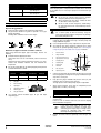
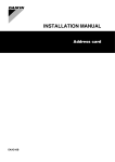
Installing near a wall or obstacle
■
Where a wall or other obstacle is in the path of the outdoor unit
air intake or exhaust airflow, follow the installation guidelines
below.
■
For any of the installation patterns below, the wall height on the
exhaust side should be 1200 mm or less.
Wall facing one side (unit: mm)
7
>100
0
33
>350
m
m
580 m
m
120 m
≤1200
m
Walls facing two sides (unit: mm)
>100
>350
>50
>50
6
5
4
1
Wrap the insulation pipe with finishing tape from bottom to top.
2
Service cover
3
Stop valve cover
4
250 mm from wall. Allow space for piping and electrical servicing.
5
If there is danger of the unit falling or overturning, fix the unit with
foundation bolts, or with wire or other means.
6
Distance from the outer side of the stop valve cover
7
If the location does not have good drainage, place the unit on
block bases. Adjust foot height until the unit is levelled. Failure to
do so may result in water leakage or accumulation.
Walls facing three sides (unit: mm)
>100
>50
Installation manual
3
>350
ERYQ005~007ABV3
Outdoor unit for air to water heat pump
3P177782-1B
INSTALLATION
4
PROCEDURE
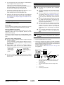
Flare the pipe. Set exactly at the position shown below.
A
Mounting the outdoor unit
When installing the outdoor unit, please refer to "Installation
guidelines" on page 2 to select an appropriate location.
1
Conventional flare tool
Check the strength and level of the installation ground so that
the unit will not cause any operating vibration or noise after
installation.
3
Clutch type
("Ridgid")
Wing nut type
("Imperial")
0~0.5 mm
1.0~1.5 mm
1.5~2.0 mm
A
5
2
Flare tool for R410A
(clutch type)
Prepare 4 sets of M8 or M10 foundation bolts, nuts and washers
each (field supply).
Fix the unit securely by means of the foundation bolts in
accordance with the foundation drawing.
It is best to screw in the foundation bolts until their length
remains 20 mm above the foundation surface.
Check that the flaring is properly made.
1
Flare's inner surface must be flaw-free.
2
The pipe end must be evenly flared in a
perfect circle.
3
Make sure that the flare nut is fitted.
1
2
3
20
Connecting the refrigerant piping to the outdoor unit
CAUTION
Drain work
■
Do not use mineral oil on flared part.
Mineral oil getting into the system would reduce the
lifetime of the units.
■
Never use piping which has been used for previous
installations. Only use parts which are delivered with
the unit.
■
Do never install a drier to this R410A unit in order to
guarantee its lifetime. The drying material may
dissolve and damage the system.
■
Incomplete flaring may cause refrigerant gas leakage.
If drain work is necessary, follow the guidelines below.
■
Install the drain plug for drainage.
■
If the drain port is covered by a mounting base or floor surface,
place additional foot bases of at least 30 mm in height under the
outdoor unit's feet.
■
In cold areas, do not use a drain hose with the outdoor unit.
Otherwise, drain water may freeze, impairing the heating
performance. In case the use of a drain hose is unavoidable for
one reason or another, it is recommended to install a heater
tape in order to protect drain from freezing.
1
To prevent gas leakage, apply refrigeration machine oil on both
inner and outer surfaces of the flare (use refrigeration oil for
R410A).
2
Align the centres of both flares and tighten the flare nuts 3 or 4
turns by hand. Then tighten them fully with torque wrenches.
1
2
3
4
1
Drain-water hole
2
Bottom frame
3
Drain plug
4
Hose (field supply, inner diameter 16 mm)
Use torque wrenches when tightening the flare nuts to prevent
damage to the flare nuts and to prevent escaping of gas.
Flaring the pipe end
To flare each pipe end, follow the procedure below:
Cut the pipe end with a pipe cutter.
2
Remove burrs with the cut surface facing downward so that the
chips do not enter the pipe.
3
1
Cut exactly at right angles.
2
Remove burrs
Torque wrench
2
Spanner
3
Piping union
4
Flare nut
1
2
3
4
1
1
1
2
Flare nut
Flare nut tightening torque
Ø6.4 mm (1/4")
14.2~17.2 N•m
(144~175 kgf•cm)
Ø15.9 mm (5/8")
61.8~75.4 N•m
(630~769 kgf•cm)
Remove the flare nut from the stop valve and put the flare nut on
the pipe.
ERYQ005~007ABV3
Outdoor unit for air to water heat pump
3P177782-1B
Installation manual
4
Purging air and checking gas leakage
Valve cap tightening torque
Valve cap
Gas pipe
Ø6.4 mm (1/4")
21.6~27.4 N•m
(220~280 kgf•cm)
Ø15.9 mm (5/8")
44.1~53.9 N•m
(450~550 kgf•cm)
When all piping work is completed and the outdoor unit is connected
to the indoor unit, it is necessary to purge the air and check for gas
leakage.
WARNING
Service port cap tightening torque
10.8~14.7 N•m (110~150 kgf•cm)
Refrigerant piping work
■
Do not mix any substance other than the specified
refrigerant (R410A) into the refrigeration cycle.
■
When refrigerant gas leaks occur, ventilate the room
as soon and as much as possible.
■
R410A, as well as other refrigerants, should always
be recovered and never be released directly into the
environment.
Pipe handling guidelines
■
Protect the open end of the pipe against dust and moisture.
■
All pipe bends should be as gentle as possible. Use a pipe
bender for bending.
Bending radius should be 30 to 40 mm or larger.
CAUTION
Use a vacuum pump for R410A exclusively. Using the
same vacuum pump for different refrigerants may damage
the vacuum pump or the unit.
■
If using additional refrigerant, perform air purging from the
refrigerant pipes and indoor unit using a vacuum pump, then
charge additional refrigerant.
■
Use a hexagonal wrench (4 mm) to operate the stop valve rod.
■
All refrigerant pipe joints should be tightened with a torque
wrench at the specified tightening torque. See "Connecting the
refrigerant piping to the outdoor unit" on page 4 for details.
Selection of copper and heat insulation materials
When using commercial copper pipes and fittings, observe the
following:
■
■
1
Pressure meter
2
Gauge manifold
Insulation material: polyethylene foam
Heat transfer rate: 0.041 to 0.052 kW/mK (0.035 to 0.045 kcal/
mh°C)
Refrigerant gas pipe's surface temperature reaches 110°C max.
Choose heat insulation materials that will withstand this
temperature.
3
Low-pressure valve (Lo)
4
High-pressure valve (Hi)
5
Charging hoses
6
Vacuum pump
7
Service port
Be sure to insulate both the gas and liquid piping and to provide
insulation dimensions as below.
8
Valve lids
9
Gas stop valve
10
Liquid stop valve
Pipe size
■
Pipe insulation
Outer
diameter
Thickness
6.4 mm (1/4")
15.9 mm (5/8")
Inner diameter
Thickness
0.8 mm
8-10 mm
≥10 mm
1.0 mm
16-20 mm
≥13 mm
1
Gas pipe
2
Inter-unit wiring
3
Liquid pipe
4
Liquid pipe insulation
5
Finishing tape
6
Gas pipe insulation
8
2
3
10
5
6
7 8 9
Connect the projection side (on which the worm pin is pressed)
of the charging hose coming from the gauge manifold to the gas
stop valve's service port.
2
Fully open the gauge manifold's low-pressure valve (Lo) and
completely close its high-pressure valve (Hi).
The high-pressure valve subsequently requires no operation.
3
Apply vacuum pumping. Check that the compound pressure
gauge reads –0.1 MPa (–760 mm Hg).
3
4
Use separate thermal insulation pipes for gas and liquid
refrigerant pipes.
4
1
2
1
6
5
1
Pipe length
Run time
4
≤15 m
>15 m
≥10 minutes
≥15 minutes
Close the gauge manifold's low-pressure valve (Lo) and stop the
vacuum pump.
Leave as is for 4-5 minutes and make sure that the coupling
meter needle does not go back.
NOTE
5
Installation manual
5
If the meter needle does go back, this may
indicate presence of moisture or leaking from
connecting parts. Repeat steps 2 through 4 after
checking all connecting parts and slightly
loosening and retightening the nuts.
Remove the covers from the liquid stop valve and gas stop
valve.
ERYQ005~007ABV3
Outdoor unit for air to water heat pump
3P177782-1B
6
Turn the liquid stop valve's rod 90 degrees counterclockwise
with a hexagonal wrench to open the valve.
Wiring
Close it after 5 seconds, and check for gas leakage.
Using soapy water, check for gas leakage from the indoor unit's
flare and the outdoor unit's flare and the valve rods.
After the check is complete, wipe all soapy water off.
7
WARNING
Disconnect the charging hose from the gas stop valve's service
port, then fully open the liquid and gas stop valves.
Do not attempt to turn the valve rod beyond its stop.
8
■
All wiring must be performed by an authorized
electrician.
■
The power supply cable and circuit breaker must be
selected in accordance with local and national
regulations.
■
Do not use tapped wires, stranded conductor wires
(see caution 1 under "Notes to observe" on page 7),
extension cords, or connections from a star system,
as they may cause overheating, electrical shock or
fire.
■
Do not use locally purchased electrical parts inside
the product and do not branch the power for the
heater tape, etc., from the terminal block. Doing this
may cause electrical shock or fire.
■
Be sure to install an earth leakage circuit breaker.
This unit uses an inverter, which means that an earth
leakage circuit breaker capable of handling high
harmonics needs to be used in order to prevent
malfunctioning of the earth leakage circuit breaker
itself.
■
Use an all-pole disconnection type breaker with a
contact separation of at least 3 mm inbetween all
poles.
Tighten the valve lids and service port caps for the liquid and
gas stop valves with a torque wrench at the specified torques.
See "Connecting the refrigerant piping to the outdoor unit" on
page 4 for details.
Charging refrigerant
This outdoor unit is factory charged.
Re-charging
In case re-charging is required, refer to the nameplate of the unit. The
nameplate states the type of refrigerant and necessary amount.
Charging additional refrigerant
If the total length of refrigerant piping exceeds 10 m in length,
additionally charge with 20 g of refrigerant (R410A) for each
additional meter of piping.
WARNING
Determine the weight of refrigerant to be charged additionally and fill
in the amount in the service sticker on the rear side of the stop valve
cover.
Do not turn ON the safety breaker until all work is
completed.
Precautions when adding R410A
Procedure
■
1
Strip the insulation from the wire (20 mm).
2
Connect the connection wires between the indoor and outdoor
units so that the terminal numbers match (see wiring diagram
below). Tighten the terminal screws securely. We recommend a
flathead screwdriver to tighten the screws.
See also caution 2 under "Notes to observe" on page 7 for
wiring guidelines.
■
Be sure to charge the specified amount of refrigerant in liquid
state to the liquid pipe.
Since this refrigerant is a mixed refrigerant, adding it in gas form
may cause the refrigerant composition to change, preventing
normal operation.
Before charging, check whether the refrigerant cylinder is
equipped with a siphon tube or not (the cylinder should be
marked with "liquid filling siphon attached" or something similar).
Charge the liquid
refrigerant with the
cylinder in upright
position.
Charge the liquid
refrigerant with the
cylinder in up-side-down
position.
1 2 3
123
LN
2
9 10 11
■
Be sure to use tools exclusively for R410A to ensure required
pressure resistance and to prevent foreign materials from mixing
into the system.
9
10
11
50 Hz
230 V
H05VV
1
ERYQ005~007ABV3
Outdoor unit for air to water heat pump
3P177782-1B
3 4
5
1
Interconnection between indoor unit and outdoor unit : when
wire length exceeds 10 m, use Ø2.5 mm wires instead of
Ø1.5 mm wires.
2
Power supply cable
(refer to the unit nameplate for maximum running current)
3
Earth
4
Safety breaker
5
Earth leakage circuit breaker
Installation manual
6
3
Earth terminal installation
CAUTION
This unit must be earthed.
NOTE
1.
For earthing, follow the applicable local standard
for electrical installations.
■ Use the following method when installing single core wires.
In case the use of stranded conductor wires is
unavoidable for one reason or another, make sure to
install round crimp-style terminals on the tip.
Place the round crimp-style terminal on the wire up to
the covered part and fasten the terminal with the
appropriate tool.
32
AA'
A
A'
3
2
1
1
1
Single core wire
2
Screw
3
Flat washer
2.
1
1
Stranded conductor wire
2
Round crimp-style terminal
When connecting the connection wires to the terminal
board using a single core wire, be sure to perform
curling.
■ Use the following method when using round crimp-style
terminals.
32
1 2 3
B
Not executing the connections properly may cause
heat and fire.
Strip the wire at terminal block:
B
1
1
4
1
Round crimp-style terminal
2
Screw
3
Flat washer
Pull the connected wire and make sure that it does not
disconnect. Then fix the wires in place in the wire clamp. See
also "Notes to observe" on page 7.
2
1
Strip wire end to this point
2
Excessive strip length may cause electrical shock
or leakage.
Notes to observe
Observe the notes mentioned below when wiring to the power supply
terminal board.
1
1
2
2
L
3
N
3
■
Use the specified wire type and connect it securely (1).
■
Firmly secure the wire clamp so that wire terminations do not
receive external stress (2).
■
Shape wires so that the service cover and stop valve cover fit
securely (3).
Installation manual
7
ERYQ005~007ABV3
Outdoor unit for air to water heat pump
3P177782-1B
TEST
PUMP
RUN AND FINAL CHECK
Remark that during the first running period of the unit,
required power input may be higher than stated on the
nameplate of the unit. This phenomenon originates
from the compressor that needs elapse of a 50 hours
run in period before reaching smooth operation and
stable power consumption.
NOTE
Trial operation and testing
DOWN OPERATION
In order to protect the environment, be sure to pump down when
relocating or disposing of the unit. The pump down operation will
extract all refrigerant from the piping into the outdoor unit.
Pump down procedure
1
Remove the valve lid from liquid stop valve and gas stop valve.
2
Carry out the forced cooling operation.
1
Measure the voltage at the primary side of the safety breaker.
Check that it is 230 V.
3
2
Carry out the test operation in accordance with the indoor
installation manual and operation manual to ensure that all
functions and parts are working properly.
After 5 to 10 minutes (after only 1 or 2 minutes in case of very
low ambient temperatures (<–10°C)), close the liquid stop valve
with a hexagonal wrench.
4
After 2-3 minutes, close the gas stop valve and stop forced
cooling operation.
■
NOTE
■
The unit requires a small amount of power in
its standby mode. If the system is not to be
used for some time after installation, shut off
the circuit breaker to eliminate unnecessary
power consumption.
1
Gas stop valve
2
Close
3
Hexagonal wrench
4
Valve lid
If the circuit breaker trips to shut off the
power to the outdoor unit, the system will
restore the original operation mode when the
power supply is restored.
5
Liquid stop valve
3
1
4
5
4
Forced cooling operation
Items to check
Check
2
Symptom
■
Outdoor unit is installed properly
on solid base.
Fall, vibration, noise
■
No refrigerant gas leaks.
Incomplete cooling/heating
function
■
Refrigerant gas and liquid pipes
are thermally insulated.
Water leakage
■
System is properly earthed.
Electrical leakage
■
The specified wires are used for
interconnecting wire connections.
Inoperative or burn damage
■
Outdoor unit air intake and
exhaust is free of obstructions.
Stop valves are opened.
Incomplete cooling/heating
function
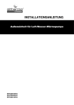
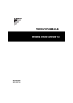
1
Press the forced operation switch SW1 to begin forced cooling.
2
Press the forced operation switch SW1 again to stop forced
cooling.
S102
NOTE
S2
Have the customer actually operate the unit while
looking at the manual included with the indoor unit.
Instruct the customer how to operate the unit correctly.
ON
A B CD
LED-A
SW4
SW1
1
1
Forced operation switch SW1
DISPOSAL
REQUIREMENTS
Dismantling of the unit, treatment of the refrigerant, of oil and of other
parts must be done in accordance with relevant local and national
legislation.
ERYQ005~007ABV3
Outdoor unit for air to water heat pump
3P177782-1B
Installation manual
8
Zandvoordestraat 300, B-8400 Oostende, Belgium
3P177782-1B